YAIWM05-ANWiFi Module
InnoComm Mobile Technology Corporation
Click to zoom
Application Details
- Equipment Class
- DTS - Digital Transmission System
- Date of Grant
- Aug 20, 2015
- Application Purpose
- Original Equipment
- Date of Application
- Aug 20, 2015
- Equipment Note
- WiFi Module
- Frequency Range
- 2412.00000000 - 2462.00000000
- Country
- Taiwan
Documents & Files
Document Text
Text extracted from the exhibit documents filed with the FCC. Open a document above to read the original.
Users Manual
iCOM_WM05 _AN Module EVB_QSG REV 0.1 8/14/2015 InnoComm Mobile Technology Corporation 3F, No. 6, Hsin Ann Rd., Hsinchu Science Park, Hsinchu 30078, Taiwan TEL: +886 -3-5781868 FAX: +886 -3-5781 187 User Manual Model name : WM05_AN FCC ID: YAI WM05 -AN iCOM_WM05 _AN Module EVB_QSG REV 0.1 8/14/2015 [General Information] The WM05_AN Eval uation Module Kit contains two WM05_AN (TI CC3200 ) modules supported USB to UART interface which is prepared for WiFi performance testing purpose. WM05_AN module provides excellent low power consumption with astonishing wireless connection range. Part Number WM05_AN Photo Description WiFi module Size (mm) 20.5x 24 x2. 3 Pin count 63 Mounting Method SMD Supply Voltage 2.5V ~ 3.6V I/O GPIO x23 Wifi connect to UART Interface Your package contains 1. WM0 5_AN EVB 2. 2 x software: USB driver & PC tool for performance test iCOM_WM05 _AN Module EVB_QSG REV 0.1 8/14/2015 EVB Drive FTDI2232D Uniflash: http://www.ti.com/tool/uniflash Radio Tool: http://www.ti.com/tool/cc3xxxradiotest [EVB ] Uniflash (to flash applications): 1. Please make sure programmer jumper is closed. Once Uniflash is installed (uniflash_cc3xxx_setup_3.2.0.00019.exe), invoke ‘CCS UniFlash’. iCOM_WM05 _AN Module EVB_QSG REV 0.1 8/14/2015 2. ‘CCS UniFlash’ will open like below. 3. Go to ‘New Target Configurations’ and do the settings as shown below. iCOM_WM05 _AN Module EVB_QSG REV 0.1 8/14/2015 4. Select the correct COM port. For correct COM port please see the next section, ‘Radio tool (to control the device)’. 5. Click on /sys/mcuimg.bin and browse for required binary file For example, flashing the launchpad with the ‘Radio Tool Application’, select the following binary available in the path shown below: C: \ti \CC3XXXRadioTool-0.5 \CC32xxBoardApplication_Binary\RadioTool_V1p1_PG1p32.bin Check ‘Erase’ and ‘Update’. iCOM_WM05 _AN Module EVB_QSG REV 0.1 8/14/2015 6. Go back to ‘CC31x Flash Setup and Control’ and click ‘Program’ After programming the device remove programmer jumper. This removal is VERY important before any testing to be done. Reset the board using the RESET push-button Radio tool (to control the device): 1. Once the device is powered up (after connecting uUSB cable to ‘power jumper’), one COM port should be enumerated in the device manger. Incase windows is not able to find the device drivers then the drivers need to be installed separately. With the SDK0.51 package installed, the driver should be available in below location. 2. Assuming (in the ‘required installation’ section), ‘CC3XXXRadioTool-0_5.exe’ is already installed, invoke ‘CC3XXX Radio Tool’ from ‘All Programs -> Texas Instruments -> CC3XXXRadioTool-0.5 -> CC3XXX Radio Tool.’ iCOM_WM05 _AN Module EVB_QSG REV 0.1 8/14/2015 The Radio Tool GUI will appear as shown below. 3. For CC3200 module launchpad, select CC3200 UART as ‘Device’. Select the COM port found in device manager. please select COM25 as shown below. Click ‘Connect’. iCOM_WM05 _AN Module EVB_QSG REV 0.1 8/14/2015 4. Once the device is connected, the GUI would show ‘Chip ID’, ‘ROM Ver’, ‘FW Ver’ and ‘MAC Address’ 5. For RX measurements go to ‘RX’ tab of the Radio Tool GUI. Select the channel intended and set the duration (example 5secs). Click ‘Start RX Testing’ and after 5 secs, the statistics will appear in the GUI. 6. Example: With 6OFDM packets at -82dBm (when the sensitivity is -89dBm) at channel 2442M, when 1000 packets are received, the statistics shown on the GUI would be as shown below. iCOM_WM05 _AN Module EVB_QSG REV 0.1 8/14/2015 The steps are similar to other rates as well. For TX measurements go to ‘TX’ tab. Before starting TX operations following settings need to be done on the GUI. TX Mode: Select ‘Packetized’ Rates: Select the modulation rates want to transmit o 11b: 1, 2, 5.5 and 11 Mbps o 11g: 6, 9, 12, 18, 24, 36, 48 and 54 Mbps o 11n: MCS0 to MCS7 Channel: Select the channel of transmission. Channel 1 (2412M) to channel 13 (2472M) Data Pattern: Select ‘All 0’ Power: ‘0’ for max power level the device can transmit at. Always use power level “0” for emission testing in order to verify the max power level settings. Preamble: Select ‘Long’ Override CCA: Should be unchecked Size: 100 Bytes (for 11b rates), 1000 Bytes (for 11g rates) and 1000 Bytes (for 11n rates) Delay: 100msec Tone: 0 Amount: 0 7. Once the above setting are done, start TX by clicking ‘Start Tx Testing’ iCOM_WM05 _AN Module EVB_QSG REV 0.1 8/14/2015 Picture 20 If to change channel or modulation rate please first click ‘Stop TX testing’. If Change To new channel or modulation rate is OK , Please click ‘Start Tx Testing’ TX -> change settings -> st art TX sequence to be followed. Picture 20: Example of 11b (1DSSS) transmission at channel 7(2442 MHz ) Picture 21 Picture 21: Example of 11g (54OFDM) transmission at channel 7(2442 MHz) iCOM_WM05 _AN Module EVB_QSG REV 0.1 8/14/2015 Picture 22 Picture 22: Example of 11n (MCS7) transmission at channel 7(2442 MHz ) [Software application development] Development support The CC3200 includes a set of tools and documentation to help the user during the development phase. PinMux Tool: The CC3200 device uses pin multiplexing extensively to accommodate the large number of peripheral functions in the smallest possible package. The PinMux tool is a utility used to select the appropriate pin multiplexing configuration that meets the end application requirements. The PinMux tool makes it easy to understand the various pin multiplexing options and enables the best configuration to be chosen without error. Radio Tool: The SimpleLink radio tool is a utility for operating and testing the CC3200 chipset designs during development of the application board. The CC3200 device has an auto-calibrated radio that enables easy connection to the antenna without requiring expertise in radio circuit design. Uniflash Flash Programmer: The Uniflash flash programmer utility allows end users to communicate with the SimpleLink device…
Text truncated - open the document above for the full version.
Cover Letter(s)
FCC ID: YAIWM05-AN Report No.: RF150722C36 Modular Approval Request Letter Bureau Veritas Consumer Products Services (H.K.) Ltd., Taoyuan Branch August 17, 2015 Dear Application Examiner, InnoComm Mobile Technology Corporation, It’s a WiFi Module, FCC ID: YAIWM05-AN would like to have your authorization as a modular device. The requirements of section 15.212 of FCC rules have been met and shown on the following statements. 1. “The modular transmitter must have its own RF shielding.”: The radio portion of this module has been shielded, please see exhibition External Photo. 2. “The modular transmitter must have buffered modulation/data inputs.” The EUT has buffered data inputs, it is integrated in chip CC3200. 3. “The modular transmitter must have its own power supply regulation.” The part number of this regulator is CC3200. 4. “The modular transmitter must comply with the antenna requirements of section 15.203 and 15.204(C).” The EUT meets the FCC antenna requirements. The spurious emission, unique antenna connector and photo of antennas are shown in the test report. 5. “The modular transmitter must be tested in a stand-alone configuration” The EUT was tested in a stand-alone configuration via extender. Please see section Photographs of Test Configuration in the test report, the EUT was plugged in this extender. 6. “The modular transmitter must be labeled with its own FCC ID number.” Please see exhibition Label Sample for the FCC ID of this module. And also in the exhibition Users Manual, there are instructions give to the OEM on how to label the end product. FCC ID: YAIWM05-AN Report No.: RF150722C36 7. “The modular transmitter must comply with any specific rule or operating requirements applicable to the transmitter and the manufacturer must provide adequate instructions along with the module to explain any such requirements.” The EUT is compliant with all applicable FCC rules. Detail instructions for maintaining compliance are given in the Users Manual. 8. “The modular transmitter must comply with any applicable RF exposure requirements.” The EUT is compliant with all applicable RF exposure requirements. RF Exposure is addressed in the RF exposure exhibition. Please contact me if you have any further questions. Thanks for your attention. Best Regards, Andrea Hsia Senior Specialist Bureau Veritas Consumer Products Services (H.K.) Ltd., Taoyuan Branch Tel: 886-3-318 3232 ext. 1628 Fax: 886-3-327 0892 Email: [email protected]
External Photos
Page 1 CONSTRUCTION PHOTOS OF EUT
ID Label/Location Info
MODIFICATION VER DESCRIPTION DATE ENGINEER
Internal Photos
Page 2 Page 3
Operational Description
FCC ID: YAIWM05-AN Report No.: RF150722C36 Operational Description This device is a WiFi Module, which operates in 2.4GHz band; the maximum data rate could be up to 72.2 Mbps which OFDM technique. If the signal to noise radio is too poor which could not support 72.2Mbps, the 11Mbps data rate with DSSS technique will be applied. The transmitter of the EUT is powered by 3.3Vdc from host equipment. The EUT is used PCB antenna without connector. The other instruction, please have a look at the user’s manual.
RF Exposure Info
Report No.: SA150722C36 Page No. 1 / 5 Report Format Version: 6.1.1 RF Exposure Report Report No.: SA150722C36 FCC ID: YAIWM05-AN Test Model: WM05_AN Received Date: Jul. 22, 2015 Test Date: Aug. 06 ~ Aug. 11, 2015 Issued Date: Aug. 13, 2015 Applicant: Innocomm Mobile Technology Corp. Address: 3F, No. 6, Hsin Ann Rd., Hsinchu Science Park, Hsinchu 30078, Taiwan Issued By: Bureau Veritas Consumer Products Services (H.K.) Ltd., Taoyuan Branch Lab Address: No. 47-2, 14th Ling, Chia Pau Vil., Lin Kou Dist., New Taipei City, Taiwan Test Location: No. 19, Hwa Ya 2nd Rd., Wen Hwa Vil., Kwei Shan Dist., Taoyuan City 33383, TAIWAN (R.O.C.) This report is for your exclusive use. Any copying or replication of this report to or for any other person or entity, or use of our name or trademark, is permitted only with our prior written permission. This report sets forth our findings solely with respect to the test samples identified herein. The results set forth in this report are not indicative or representative of the quality or characteristics of the lot from which a test sample was taken or any similar or identical product unless specifically and expressly noted. Our report includes all of the tests requested by you and the results thereof based upon the information that you provided to us. You have 60 days from date of issuance of this report to notify us of any material error or omission caused by our negligence, provided, however, that such notice shall be in writing and shall specifically address the issue you wish to raise. A failure to raise such issue within the prescribed time shall constitute your unqualified acceptance of the completeness of this report, the tests conducted and the correctness of the report contents. Unless specific mention, the uncertainty of measurement has been explicitly taken into account to declare the compliance or non-compliance to the specification. The report must not be used by the client to claim product certification, approval, or endorsement by TAF or any government agencies. Report No.: SA150722C36 Page No. 2 / 5 Report Format Version: 6.1.1 Table of Contents Release Control Record .................................................................................................................................. 3 1 Certificate of Conformity ...................................................................................................................... 4 2 RF Exposure .......................................................................................................................................... 5 2.1 Limits for Maximum Permissible Exposure (MPE) .............................................................................. 5 2.2 MPE Calculation Formula ................................................................................................................... 5 2.3 Classification ....................................................................................................................................... 5 3 Calculation Result of Maximum Conducted Power ........................................................................... 5 Report No.: SA150722C36 Page No. 3 / 5 Report Format Version: 6.1.1 Release Control Record Issue No. Description Date Issued SA150722C36 Original release. Aug. 13, 2015 Report No.: SA150722C36 Page No. 4 / 5 Report Format Version: 6.1.1 1 Certificate of Conformity Product: WiFi Module Brand: InnoComm Mobile Test Model: WM05_AN Sample Status: Engineering sample Applicant: Innocomm Mobile Technology Corp. Test Date: Aug. 06 ~ Aug. 11, 2015 Standards: FCC Part 2 (Section 2.1091) KDB 447498 D03 IEEE C95.1 The above equipment has been tested by Bureau Veritas Consumer Products Services (H.K.) Ltd., Taoyuan Branch, and found compliance with the requirement of the above standards. The test record, data evaluation & Equipment Under Test (EUT) configurations represented herein are true and accurate accounts of the measurements of the sample’s EMC characteristics under the conditions specified in this report. Prepared by : , Date:Aug. 13, 2015 Pettie Chen / Senior Specialist Approved by : , Date:Aug. 13, 2015 Ken Liu / Senior Manager Report No.: SA150722C36 Page No. 5 / 5 Report Format Version: 6.1.1 2 RF Exposure 2.1 Limits for Maximum Permissible Exposure (MPE) Frequency Range (MHz) Electric Field Strength (V/m) Magnetic Field Strength (A/m) Power Density (mW/cm 2 ) Average Time (minutes) Limits For General Population / Uncontrolled Exposure 300-1500 ... ... F/1500 30 1500-100,000 ... ... 1.0 30 F = Frequency in MHz 2.2 MPE Calculation Formula Pd = (Pout*G) / (4*pi*r 2 ) where Pd = power density in mW/cm 2 Pout = output power to antenna in mW G = gain of antenna in linear scale Pi = 3.1416 R = distance between observation point and center of the radiator in cm 2.3 Classification The antenna of this product, under normal use condition, is at least 20cm away from the body of the user. So, this device is classified as Mobile Device. 3 Calculation Result of Maximum Conducted Power Frequency Band (MHz) Max Power (dBm) Antenna Gain (dBi) Distance (cm) Power Density (mW/cm 2 ) Limit (mW/cm 2 ) 2412-2462 19.93 -2.0 20 0.012 1 ---END---
Test Report
Report No.: RF150722C36 Page No. 1 / 46 Report Format Version: 6.1.1 FCC Test Report Report No.: RF150722C36 FCC ID: YAIWM05-AN Test Model: WM05_AN Received Date: Jul. 22, 2015 Test Date: Aug. 06 ~ Aug. 11, 2015 Issued Date: Aug. 13, 2015 Applicant: Innocomm Mobile Technology Corp. Address: 3F, No. 6, Hsin Ann Rd., Hsinchu Science Park, Hsinchu 30078, Taiwan Issued By: Bureau Veritas Consumer Products Services (H.K.) Ltd., Taoyuan Branch Lab Address: No. 47-2, 14th Ling, Chia Pau Vil., Lin Kou Dist., New Taipei City, Taiwan Test Location: No. 19, Hwa Ya 2nd Rd., Wen Hwa Vil., Kwei Shan Dist., Taoyuan City 33383, TAIWAN (R.O.C.) This report is for your exclusive use. Any copying or replication of this report to or for any other person or entity, or use of our name or trademark, is permitted only with our prior written permission. This report sets forth our findings solely with respect to the test samples identified herein. The results set forth in this report are not indicative or representative of the quality or characteristics of the lot from which a test sample was taken or any similar or identical product unless specifically and expressly noted. Our report includes all of the tests requested by you and the results thereof based upon the information that you provided to us. You have 60 days from date of issuance of this report to notify us of any material error or omission caused by our negligence, provided, however, that such notice shall be in writing and shall specifically address the issue you wish to raise. A failure to raise such issue within the prescribed time shall constitute your unqualified acceptance of the completeness of this report, the tests conducted and the correctness of the report contents. Unless specific mention, the uncertainty of measurement has been explicitly taken into account to declare the compliance or non-compliance to the specification. This report should not be used by the client to claim product certification, approval, or endorsement by TAF or any government agencies. Report No.: RF150722C36 Page No. 2 / 46 Report Format Version: 6.1.1 Table of Contents Release Control Record .................................................................................................................................. 4 1 Certificate of Conformity ...................................................................................................................... 5 2 Summary of Test Results ..................................................................................................................... 6 2.1 Measurement Uncertainty ................................................................................................................... 6 2.2 Modification Record ............................................................................................................................ 6 3 General Information .............................................................................................................................. 7 3.1 General Description of EUT ................................................................................................................ 7 3.2 Description of Test Modes ................................................................................................................... 8 3.2.1 Test Mode Applicability and Tested Channel Detail ............................................................................. 9 3.3 Duty Cycle of Test Signal ................................................................................................................... 11 3.4 Description of Support Units ............................................................................................................. 12 3.4.1 Configuration of System under Test .................................................................................................. 12 3.5 General Description of Applied Standards ........................................................................................ 13 4 Test Types and Results ...................................................................................................................... 14 4.1 Radiated Emission and Bandedge Measurement ............................................................................. 14 4.1.1 Limits of Radiated Emission and Bandedge Measurement .............................................................. 14 4.1.2 Test Instruments ................................................................................................................................ 15 4.1.3 Test Procedures ................................................................................................................................. 16 4.1.4 Deviation from Test Standard ............................................................................................................ 16 4.1.5 Test Set Up ........................................................................................................................................ 17 4.1.6 EUT Operating Conditions ................................................................................................................. 17 4.1.7 Test Results ....................................................................................................................................... 18 4.2 Conducted Emission Measurement .................................................................................................. 28 4.2.1 Limits of Conducted Emission Measurement .................................................................................... 28 4.2.2 Test Instruments ................................................................................................................................ 28 4.2.3 Test Procedures ................................................................................................................................. 29 4.2.4 Deviation from Test Standard ...............................…
Text truncated - open the document above for the full version.
Test Setup Photos
1 PHOTOGRAPHS OF THE TEST CONFIGURATION CONDUCTED EMISSION TEST 2 3 RADIATED EMISSION TEST (Above 1GHz) 4 RADIATED EMISSION TEST (Below 1GHz)
Contact Information
Applicant
Bruno Tsai(Product manager)
Test Firm
Bureau Veritas CPS (H.K.) Ltd., Taoyuan BranchRichard Chen
Technical Specifications
| # | Rule Parts | Frequency Range | Power Output |
|---|---|---|---|
| 1 | 15C | 2.41 GHz - 2.46 GHz | 98.00 mW |
Other Applications from InnoComm Mobile Technology Corporation
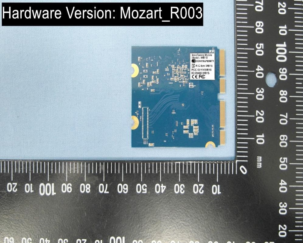
YAIWB15
Nov 14, 2020Wireless Audio Module
Equipment Class
NII - Unlicensed National Information Infrastructure TX
YAISB52
May 31, 2020Wireless SOM Module
Equipment Class
DTS - Digital Transmission System
YAIBM05-AN
Sep 17, 2014BT4.0 LE Module
Equipment Class
DTS - Digital Transmission System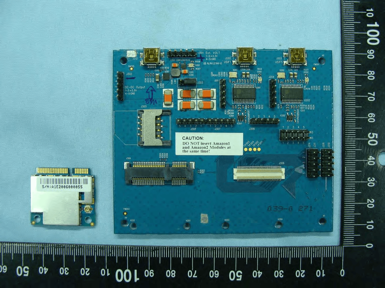
YAI1901
Aug 18, 20103.5G data card
Equipment Class
PCB - PCS Licensed Transmitter