YAK22102S+ By ResMed
Resmed Sensor Technologies Ltd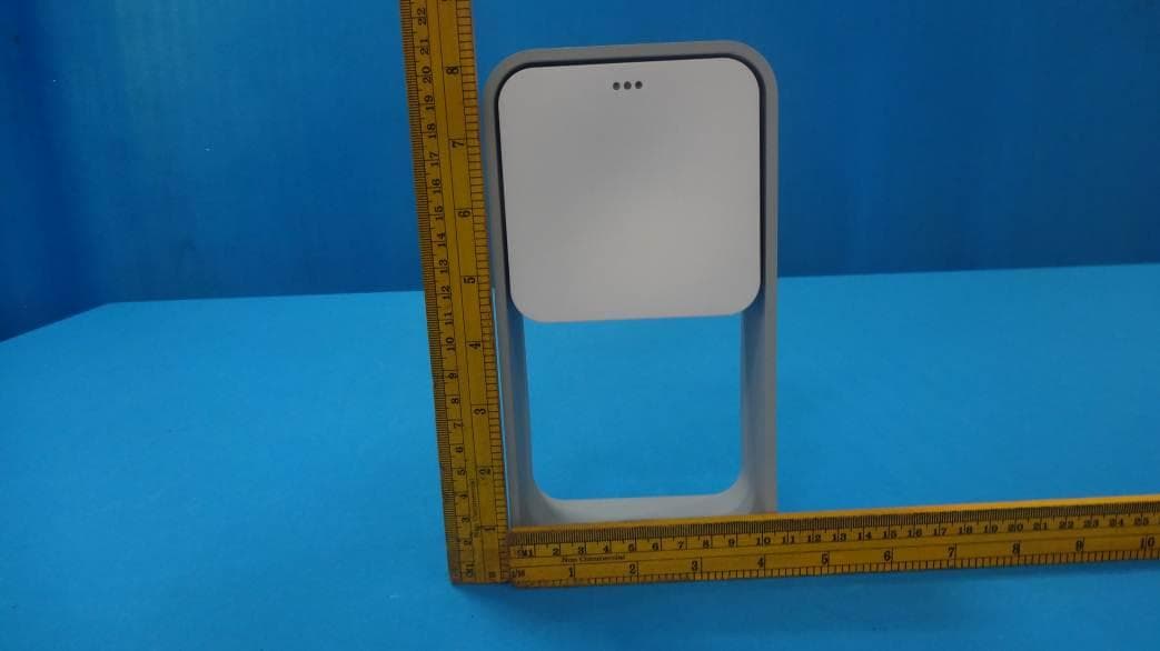
Click to zoom
Application Details
- Equipment Class
- DSS - Part 15 Spread Spectrum Transmitter
- Date of Grant
- Jul 05, 2014
- Application Purpose
- Original Equipment
- Date of Application
- Jun 30, 2014
- Equipment Note
- S+ By ResMed
- Frequency Range
- 2402.00000000 - 2480.00000000
- Country
- Ireland
Documents & Files
Document Text
Text extracted from the exhibit documents filed with the FCC. Open a document above to read the original.
Users Manual
1 Sleep better User Manual 32 9001 Spectrum Center Blvd, San Diego, CA 92123, USA. http://www.mySplus.com ResMed Corp Congratulations on your purchase of the S+ by ResMed. This booklet is designed to guide you through setting up your S+ bedside device for the first time. It will clearly explain how to pair the device with your iPhone®/Android™ smartphone or tablet, and will also provide details on key features of the S+ by ResMed smartphone app. The S+ contains one of the most pioneering, non-contact sleep sensors on the market, and, when paired with a compatible smartphone or tablet, gives you access to a powerful analysis tool that will provide you with tailored feedback to help improve your sleep. We at ResMed have years of research and expertise as a global leader in the development of products for the diagnosis, treatment and management of respiratory disorders, with a focus on sleep-disordered breathing. This expertise in sleep science has enabled us to design important features to actively help you improve your sleep. Please read the instructions before using your S+. Sleep better, The S+ by ResMed Team Welcome to Better Sleep! 54 Table of Contents What’s Included Downloading the App App Setup How to Set up your S+ Pairing your S+ LED Indicator Sleep Basics App Features Positioning your S+ Tracking your First Sleep Product Information Warranty Disclaimer 6 8 9 10 12 14 16 18 22 25 26 32 34 76 What’s Included Pod Frame Power Supply UnitUSB Cable Note The Power Supply Unit should not be used to charge an iPad® or iPad mini™ The S+ is designed to improve sleep through coaching and biofeedback. It is not a medical device. If you have concerns that sleep is affecting your health, you should consult your physician. The pod is the engine of the S+ which captures your sleep and bedroom environment data. It uses highly accurate patented sensor technology to monitor your breathing and body movement. In addition, it measures the ambient light, temperature and noise levels as these can affect your sleep. The front of the pod features the S+ logo and also features a small LED which indicates whether or not the pod is connected. The back of the pod contains a micro USB socket for the power cable. The frame is used to hold the pod and to ensure it is positioned above the level of the mattress. The power cable connects your pod to the power supply unit. The power supply unit provided is a certified AC-DC adaptor and features two USB outlets. One is to power your pod using the USB power cable supplied. The second USB power outlet is to allow you to plug in your smartphone or tablet cable for charging. The pod must only be powered via the power supply unit supplied and not through other USB outlets, such as those on a laptop or docking station. The Pod The Frame The USB Power Cable The Power Supply Unit The USB power cable supplied should be used for the S+ unit only. Warning 98 How’s Your Sleep? App Setup Once you have downloaded the app, open it and follow the on-screen instructions to register your details. Give the S+ Mentor feature a little information by answering a few questions about you, your sleeping patterns and lifestyle. This is one of the ways we ensure the feedback you will receive is tailored to your individual requirements. Sign Up At this point, we recommend you take our app tour, the S+ Guide, to help you get the best results from your S+ and better understand how it can help improve your sleep performance. You can access this tour at any time through the Settings menu. Take the App Tour Note Actual lay-out of screens may vary depending on what operating system you are using. Downloading the App Download the S+ by ResMed app from the Apple App Store or Google Play stores. Simply search for “S+ by ResMed” or follow the link from our website www. mySplus.com. For a list of compatible smartphones and tablets, please check: http://www.mySplus.com/help Before you follow these set-up instructions please ensure that Bluetooth and WiFi are switched on on your smartphone or tablet. Do not power up your S+ bedside device until instructed to do so. Important 1110 How to set up your S+ Insert the power cable into the micro USB socket in the back of the pod. Connect the other end of the USB power cable into one of the USB outlets in the power supply unit. Plug the power supply unit into the AC wall outlet. Connect Cable Connect to Outlet Info You can use the power supply unit provided to charge your smartphone. A phone charging cable is not supplied. Please use your own charger/cable if using the S+ with a tablet. We recommend you charge your smartphone or tablet while using the S+. Charge Device 1312 The S+ communicates to your compatible smartphone or tablet via Bluetooth. After taking the app tour, the app will guide you through connecting to the bedside device via Bluetooth. Connecting with Bluetooth Pairing your S+ Complete and Exit our app tour, the S+ Guide. Select “S+ by ResMed” on your available Bluetooth devices screen. Ensure that Bluetooth is switched on and the S+ is powered up. Tap on “Start”. You will see the message “Device Successfully Paired”. We recommend that you keep your smartphone or tablet in your room once you have started sleep tracking to maintain the Bluetooth connection. If the Bluetooth connection between it and your S+ is interrupted, the S+ will continue to track sleep, although it will require reconnection to transfer data to the smartphone or tablet. The S+ can be used by multiple users (i.e. paired with different phones), but only one at a time. Two S+ devices cannot be used in the same room at the same time as this will affect performance. About Bluetooth and S+ Note If your phone is in Airplane or Flight Mode, the Bluetooth function will be disabled. 1514 LED Indicator Meaning Meaning Meaning Meaning Meaning Action to take Action to take Action to take Action to take Action to take The S+ has not yet been paired for the first time. The S+ is connected and …
Text truncated - open the document above for the full version.
External Photos
www.tuv.com Appendix 2 Prüfbericht - Nr.: Test Report No. 19660105 001 Seite 1 von 4 Page 1 of 4 Over All View EUT Front View www.tuv.com Appendix 2 Prüfbericht - Nr.: Test Report No. 19660105 001 Seite 2 von 4 Page 2 of 4 EUT Side View EUT Bottom View www.tuv.com Appendix 2 Prüfbericht - Nr.: Test Report No. 19660105 001 Seite 3 von 4 Page 3 of 4 EUT Without Stand EUT Side View EUT Stand www.tuv.com Appendix 2 Prüfbericht - Nr.: Test Report No. 19660105 001 Seite 4 von 4 Page 4 of 4 EUT Dimensional View
ID Label/Location Info
ResM ed Sensor Technologies Ltd NexusUCD Block 9 & 10 Belfield Office Park Clonskeagh Dublin 4 Ireland Tel: +353 1 2096400 Fax: +353 1 2096499 ResM ed Sensor Technologies Ltd, NexusUCD, Block 9 & 10, Belfield Office Park, Clonskeagh, Dublin 4, Ireland. Tel: + 353 1 2096400 Fax: + 353 1 2096499 Registered in Ireland no:372477 VAT Reg: 6392477W Directors: C. Hanley D. Pendarvis(USA) Re: Application for YAK22102 Label Details ResM ed Sensor Technologies Ltd NexusUCD Block 9 & 10 Belfield Office Park Clonskeagh Dublin 4 Ireland Tel: +353 1 2096400 Fax: +353 1 2096499 ResM ed Sensor Technologies Ltd, NexusUCD, Block 9 & 10, Belfield Office Park, Clonskeagh, Dublin 4, Ireland. Tel: + 353 1 2096400 Fax: + 353 1 2096499 Registered in Ireland no:372477 VAT Reg: 6392477W Directors: C. Hanley D. Pendarvis(USA) Label Location
Internal Photos
www.tuv.com Appendix 3 Prüfbericht - Nr.: Test Report No. 19660105 001 Seite 1 von 3 Page 1 of 3 EUT- Enclosure Opened Internal PCB www.tuv.com Appendix 3 Prüfbericht - Nr.: Test Report No. 19660105 001 Seite 2 von 3 Page 2 of 3 Top View - bluetooth board Bottom View – Bluetooth board www.tuv.com Appendix 3 Prüfbericht - Nr.: Test Report No. 19660105 001 Seite 3 von 3 Page 3 of 3 10.5GHz Sensor
RF Exposure Info
www.tuv.com Appendix 10 Prüfbericht - Nr.: Test Report No. 19660105 001 Seite 1 von 2 Page 1 of 2 RF Exposure Report RF Exposure Measurement The limit for Maximum Permissible Exposure (MPE) specified in FCC 1.1310 is followed. The gain of the antennas used in the product is extracted from the Antenna data sheets provided and also the maximum total power input to the antenna is measured. Through the Friis transmission formula and the maximum gain of the antenna, we can calculate the distance, away from the product, where the limit of MPE is reached. Although the Friis Transmission formula is far field assumption, the calculated result of that is an over- prediction for near field power density. It is taken as worst case to specify the safety range. RF Exposure Limit According to FCC 1.1310: The criteria listed in the following table shall be used to evaluate the environmental impact of the human exposure to radio-frequency (RF) radiation as specified in 1.1307 (b) Limits for Maximum Permissible Exposure (MPE) Frequency Range (MHz) Electric Field Strength (V/m) Magnetic Field Strength (A/m) Power Density (mW/cm²) Limits for Occupational / controlled Exposures 300 - 1500 -- -- F/300 1500 – 100000 -- -- 5.0 Limits for General population / Uncontrolled Exposure 300 - 1500 -- -- F/1500 1500 – 100000 -- -- 1.0 F= Frequency in MHz www.tuv.com Appendix 10 Prüfbericht - Nr.: Test Report No. 19660105 001 Seite 2 von 2 Page 2 of 2 Friss Formula Friss Transmission Formula: Pd = (Pout * G) / (4*pi*r²) Where Pd = power density in mW/cm² Pout = output power to antenna in mW G = gain of antenna in linear scale Pi = 3.1416 R = Distance between observation point and the center of radiator in cm If we know the maximum gain of the antenna and the total output power to the antenna, through calculation, we will know MPE value at distance 20cm. EUT Operation condition EUT was enabled to transmit and receive at lowest, middle and highest channels. Classification The antenna of this product, under normal use condition, is at least 20cm away from the body of the user. So, this device is classified as Portable device. Test Results Gain (G) = dBi Protocol Data Rate (Mbps) Channel Frequency (MHz) Output Power to Antenna (mW) Power Density (mW/cm²) Limit (mW/cm²) Bluetooth 3 2402 0.814 0.0005670 1.000 10.5GHz - 10.525 8 0.001592 1.000
Test Report
Produkte Products TÜV Rheinland LGA Products GmbH Tillystraße 2 D - 90431 Nürnberg Tel.: +49 911 655 5225 Fax: +49 911 655 5226 Mail: [email protected] Web: www.tuv.com Rev.:1.2 2009-12-29 / approved: M.Jungnitsch Prüfbericht - Nr.: 19660105 001 Seite 1 von 55 Test Report No.: Page 1 of 55 Auftraggeber: Client: ResMed Sensor Technologies Ltd. Blocks 9&10, NexusUCD Building, Belfield Office Park Clonskeagh, Dublin Ireland Gegenstand der Prüfung: Test item: S+ By ResMed Bezeichnung: Identification: 22102 Serien-Nr.: Serial No. Engineering Sample Wareneingangs-Nr.: Receipt No.: 1803032534 Eingangsdatum: Date of receipt: 21.04.2014 Prüfort: Testing location: Refer Page 4 of 55 for test facilities Prüfgrundlage: Test specification: FCC Part 15 Sub Part C ANSI C63.4-2003 Prüfergebnis: Test Result: Der Prüfgegenstand entspricht oben genannter Prüfgrundlage(n). The test item passed the test specification(s). Prüflaboratorium: Testing Laboratory: TÜV Rheinland (India) Pvt. Ltd. Alpha Tower, Sigma Soft Tech Park, # 7, Whitefield Main Road, Varthur Kodi, Bangalore – 560066, India geprüft / tested by: kontrolliert / reviewed by: 30.04.2014 Vinay N Engineer 15.05.2014 Raghavendra Kulkarni Senior Manager Datum Date Name/Stellung Name/Position Unterschrift Signature Datum Date Name/Stellung Name/Position Unterschrift Signature Sonstiges /Other Aspects: FCC ID:YAK22102 Contains FCC ID: YAKBM14 Abkürzungen: P(ass) = entspricht Prüfgrundlage F(ail) = entspricht nicht Prüfgrundlage N/A = nicht anwendbar N/T = nicht getestet Abbreviations: P(ass) = passed F(ail) = failed N/A = not applicable N/T = not tested Dieser Prüfbericht bezieht sich nur auf das o.g. Prüfmuster und darf ohne Genehmigung der Prüfstelle nicht auszugsweise vervielfältigt werden. Dieser Bericht berechtigt nicht zur Verwendung eines Prüfzeichens. This test report relates to the a. m. test sample. Without permission of the test center this test report is not permitted to be duplicated in extracts. This test report does not entitle to carry any safety mark on this or similar products. www.tuv.com Test Report No.: 19660105 001 Date: 30.04.2014 Page 2 of 55 Test Result Summary Clause Test Item Result Section 15.247 (b) (1) Conducted Peak RF Output Power Test Pass Section 15.247 (a)(1) Bandwidth Occupancy Pass Section 15.247 (a)(1)(III) Number of Hopping Channels Pass Section 15.247 (a)(1) Carrier Frequency Separation Pass Section 15.247 (a)(1)(III) Time of Occupancy Pass Section 15.257 (d) Band-edge compliance Pass Section 15.209 & 15.205,15.245 Spurious Radiated Emissions Pass Section 15.207 Conducted Emission Test on a.c. Power Line Pass Note: This product contains 10.5GHz Field disturbance sensor module with FCC ID: YAKBM14. Hence module related tests are excluded. www.tuv.com Test Report No.: 19660105 001 Date: 30.04.2014 Page 3 of 55 Content List of Test and Measurement Instruments .............................................................. 4 General Product Information ..................................................................................... 5 Product Function and Intended Use ............................................................................................. 5 Ratings and System Details ........................................................................................................... 5 Operation Descriptions .............................................................................................. 6 Test Set-up and Operation Mode ............................................................................... 7 Principle of Configuration Selection ............................................................................................ 7 Test Operation and Test Software ................................................................................................ 7 Special Accessories and Auxiliary Equipment ............................................................................ 7 Countermeasures to achieve EMC Compliance .......................................................................... 7 Test Methodology ....................................................................................................... 8 Radiated Emission Test ................................................................................................................. 8 Conducted Emission Test on a.c. mains line .............................................................................. 8 Test Results ................................................................................................................. 9 Conducted Peak Output Power Section 15.247 (b) (1) ................ 9 Bandwidth Occupancy Section 15.247 (a) (1) .............. 16 Number of Hopping Channels Section (a) (1) (iii) ................... 28 Carrier Frequency Separation Section 15.247 (a) (1) .............. 30 Time of Occupancy (Dwell Time) Section 15.247 (a)(1)(III) ........... 31 Band-edge Compliance Section 15.257 (d) .................... 37 Spurious Radiated Emissions & Restricted Bands of Operation Section 15.209 & 15.205,15.245 .................................................................................................................... 47 Conducted Emission Test on a.c. Power Line Section 15.207 ........................... 53 Appendix 1: Test Setup Photo Appendix 2: EUT External Photo Appendix 3: EUT Internal Photo Appendix 4: FCC Label and Label Location Appendix 5: Block Diagram Appendix 6: Specification of EUT Appendix 7: Schematic Diagrams Appendix 8: Bill of Material Appendix 9: User Manual Appendix 10: Maximum Permissible Exposure Information www.tuv.com Test Report No.: 19660105 001 Date: 30.04.2014 Page 4 of 55 List of Test and Measurement Instruments Equipment Manufacturer Model S/N Calibration Due Date EMI Test Receiver Rohde &Schwarz ESU 40 100288 04.10.2014 Hybrid Log Periodic antenna ETS Lindgren 3142D 00081354 26.07.2014 Broadband Horn Antenna Frankonia HAX-18 HAX18-802 23.03.2015 Double-Ridge…
Text truncated - open the document above for the full version.
Test Setup Photos
www.tuv.com Appendix 1 Prüfbericht - Nr.: Test Report No. 19660105 001 Seite 1 von 3 Page 1 of 3 Test Setup Test Setup www.tuv.com Appendix 1 Prüfbericht - Nr.: Test Report No. 19660105 001 Seite 2 von 3 Page 2 of 3 Test setup Test Setup www.tuv.com Appendix 1 Prüfbericht - Nr.: Test Report No. 19660105 001 Seite 3 von 3 Page 3 of 3 Test setup
Contact Information
Applicant
Michael Wren(Product Development Manager)
Test Firm
TUV Rheinland (India) Pvt. Ltd.,B GURUPRASAD
Technical Specifications
| # | Rule Parts | Frequency Range | Power Output |
|---|---|---|---|
| 1 | 15C | 2.40 GHz - 2.48 GHz | 814.00 µW |
Other Applications from Resmed Sensor Technologies Ltd
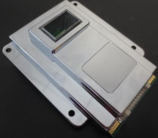
YAKBM14
Feb 16, 2014Field Disturbance Sensor
Equipment Class
FDS - Part 15 Field Disturbance Sensor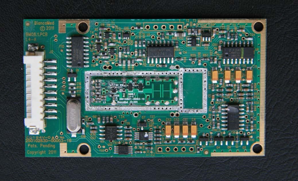
YAKBM11
Nov 01, 2011Sensor Module
Equipment Class
FDS - Part 15 Field Disturbance Sensor
YAKBM08
Mar 01, 2011Motion Detector Module
Equipment Class
FDS - Part 15 Field Disturbance Sensor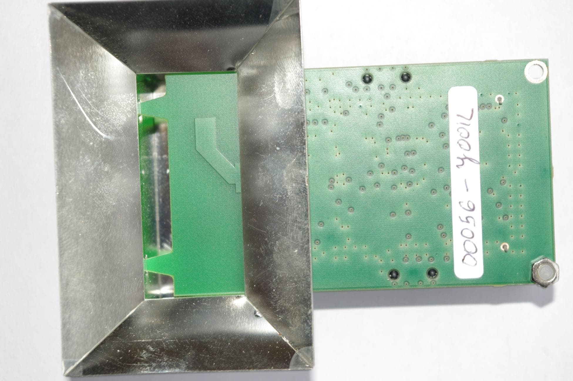
YAKBM04
May 05, 2010SleepMinder
Equipment Class
DXX - Part 15 Low Power Communication Device Transmitter