YAKBM08Motion Detector Module
Resmed Sensor Technologies Ltd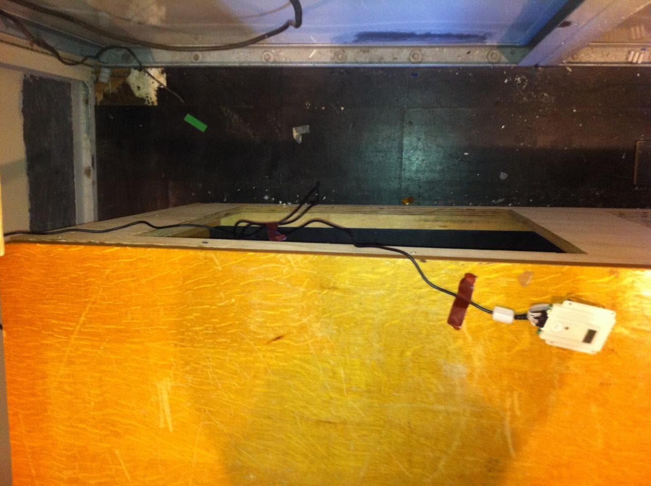
Click to zoom
Application Details
- Equipment Class
- FDS - Part 15 Field Disturbance Sensor
- Date of Grant
- Mar 01, 2011
- Application Purpose
- Original Equipment
- Date of Application
- Mar 01, 2011
- Equipment Note
- Motion Detector Module
- Frequency Range
- 10523.50000000 - 10523.50000000
- Country
- Ireland
Documents & Files
Document Text
Text extracted from the exhibit documents filed with the FCC. Open a document above to read the original.
Users Manual
BM08_2DOC_001 Page 1 User Manual User Manual The BiancaMed BM08 Sensor is a 10.525GHz motion detector. It comprises a motherboard PCBA, an integral RF PCBA, die cast RF metalwork and a custom plastic anti-tamper enclosure. Physical Specifications Parameter Value Remarks Circuit board dimensions 44.5mm by 77.5mm by 6 mm See diagram below Complete assembly (including anti-tamper enclosure) dimensions 63.75mm (x) by 79.3mm (y) by 10mm (z) main body of enclosure, 13.8 mm (z) at enclosure hump 22.5mm (z) max by horn, see Figure 2 below Figure 1: PCB Layout, showing the Antenna Horn on the top side and the connector at the bottom Page 2 Figure 2: 3-D Model of PCB Enclosed in Anti-Tamper Enclosure Radio Frequency Sensor Specifications Parameter Value Remarks Centre frequency 10.525 GHz RF t/x Pulse 500nS PRF 1MHz RF Duty Cycle 50% Electrical Specifications Parameter Value Remarks Input voltage +4.5 to 12 VDC Maximum current draw 25 mA nominal current draw 22mA Maximum voltage ripple allowed 100 nV rms /(root(Hz)) Maximum supply voltage allowed 12 VDC Minimum tolerable supply +4.5 VDC x y z Page 3 Parameter Value Remarks voltage Reference Voltage 1.25 VDC Reference Voltage line output impedance 1 kOhm Sensor start time before data is available 40 s Connector Hirose 10-Way 2mm Pitch Header Connector Analogue Sensor Data Environmental Specifications Parameter Value Remarks Operating Temperature Range +5 to +35 deg C Operating Humidity Range 30 to 85% RH (non condensing) Storage Temperature range -20 to +60C Storage Humidity Range 20 to 95 RH (non-condensing) IP value Not Applicable IP value provided by OEM enclosure Where: Input: VDC = +4.5 to +12 VDC Shutdown = active low, connect to pin 2 to enable sensor Output: Vref = +1.25 VDC M-I= Movement I channel data R-I= Respiration I channel data M-Q= Movement Q channel data R-Q= Respiration Q channel data Figure 3: Pin out of Connector Page 4 FCC Warning Statements This equipment has been tested and found to comply with the limits for a Class B digital device, pursuant to Part 15 of the FCC Rules. These limits are designed to provide reasonable protection against harmful interference in a residential installation. This equipment generates uses and can radiate radio frequency energy and, if not installed and used in accordance with the instructions, may cause harmful interference to radio communications. However, there is no guarantee that interference will not occur in a particular installation. If this equipment does cause harmful interference to radio or television reception, which can be determined by turning the equipment off and on, the user is encouraged to try to correct the interference by one of the following measures: - Reorient or relocate the receiving antenna. - Increase the separation between the equipment and receiver. - Connect the equipment into an outlet on a circuit different from that to which the receiver is connected. - Consult the dealer or an experienced radio/TV technician for help. This device complies with Part 15 of the FCC Rules. Operation is subject to the following two conditions: (1) This device may not cause harmful interference, and (2) this device must accept any interference received, including interference that may cause undesired operation. FCC Caution: Any changes or modifications not expressly approved by BiancaMed could void the user's authority to operate this equipment. This transmitter module is authorized to be used in other devices only by OEM further transmitter testing will not be required. However, the OEM integrator is still responsible for testing their end-product for any additional compliance requirements required with this module installed (for example, digital device emissions, PC peripheral requirements, etc.). The OEM integrator has to be aware not to provide information to the end user regarding how to install or remove this RF module in the user manual of the end product. End Product Labeling The final end product must be labeled in a visible area with the following: “Contains TX FCC ID: YAKBM08” or “Contains FCC ID: YAKBM08”.
External Photos
Report Ref: 10E3363-2 Exhibit B Page 1 of 12 Project Number: 10E3363-2 Prepared for: Biancamed Ltd By Compliance Engineering Ireland Ltd Ratoath Road Ashbourne Co. Meath FCC Site Registration: YAKBM08 Date 24 th February 2011 FCC EQUIPMENT AUTHORISATION Test Report EUT Description Motion Sensor Authorised: Report Ref: 10E3363-2 Exhibit B Page 2 of 12 Exhibit B – Photographs Report Ref: 10E3363-2 Exhibit B Page 3 of 12 Exhibit A – Technical Report Biancamed Ltd., Sleepminder Motion Sensor Applicant Name and Address The system covered under this authorisation report was designed, manufactured and assembled by Biancamed Ltd. The company's full name and mailing address is given below: BiancaMed Limited, NovaUCD, Belfield Innovation Park, Dublin 4, Ireland. Model Name The model number for the EUT covered under this application report is: Sleepminder Report Ref: 10E3363-2 Exhibit B Page 4 of 12 Figure 1: EUT configuration on turntable Report Ref: 10E3363-2 Exhibit B Page 5 of 12 Figure 2: Bottom of EUT Figure 3: Top of EUT Report Ref: 10E3363-2 Exhibit B Page 6 of 12 Figure 4: Side of EUT (Side A) Figure 5: Side of EUT (Side B) Report Ref: 10E3363-2 Exhibit B Page 7 of 12 Figure 6: Side of EUT (Side C) Figure 7: Side of EUT (Side D) Report Ref: 10E3363-2 Exhibit B Page 8 of 12 Figure 8: View of EUT (Cover removed – Top) Figure 9: View of EUT (Cover removed – Bottom) Report Ref: 10E3363-2 Exhibit B Page 9 of 12 Figure 10: View of PCB (Metal removed) Report Ref: 10E3363-2 Exhibit B Page 10 of 12 Figure 11: View of PCB Figure 12: View of Conducted Emissions Report Ref: 10E3363-2 Exhibit B Page 11 of 12 Figure 13: View of Conducted Emissions Report Ref: 10E3363-2 Exhibit B Page 12 of 12 Figure 14: View of Radiated Emissions Set Up above 26 GHz
ID Label/Location Info
BiancaMed Limited Tel: +353 1 716 3799 Fax: +353 1 716 3709 Website: www.biancamed.com BiancaMed Limited, Registered in Ireland No: 372477 Address: BiancaMed, NovaUCD, University College Dublin, Belfield, Dublin 4, Ireland FCC Label drawing: BiancaMed Model: BM08 FCC ID: YAKBM08 BiancaMed Limited Tel: +353 1 716 3799 Fax: +353 1 716 3709 Website: www.biancamed.com BiancaMed Limited, Registered in Ireland No: 372477 Address: BiancaMed, NovaUCD, University College Dublin, Belfield, Dublin 4, Ireland FCC Label location: Reverse of sensor module:
Internal Photos
Report Ref: 10E3363-2 Exhibit B Page 1 of 12 Project Number: 10E3363-2 Prepared for: Biancamed Ltd By Compliance Engineering Ireland Ltd Ratoath Road Ashbourne Co. Meath FCC Site Registration: YAKBM08 Date 24 th February 2011 FCC EQUIPMENT AUTHORISATION Test Report EUT Description Motion Sensor Authorised: Report Ref: 10E3363-2 Exhibit B Page 2 of 12 Exhibit B – Photographs Report Ref: 10E3363-2 Exhibit B Page 3 of 12 Exhibit A – Technical Report Biancamed Ltd., Sleepminder Motion Sensor Applicant Name and Address The system covered under this authorisation report was designed, manufactured and assembled by Biancamed Ltd. The company's full name and mailing address is given below: BiancaMed Limited, NovaUCD, Belfield Innovation Park, Dublin 4, Ireland. Model Name The model number for the EUT covered under this application report is: Sleepminder Report Ref: 10E3363-2 Exhibit B Page 4 of 12 Figure 1: EUT configuration on turntable Report Ref: 10E3363-2 Exhibit B Page 5 of 12 Figure 2: Bottom of EUT Figure 3: Top of EUT Report Ref: 10E3363-2 Exhibit B Page 6 of 12 Figure 4: Side of EUT (Side A) Figure 5: Side of EUT (Side B) Report Ref: 10E3363-2 Exhibit B Page 7 of 12 Figure 6: Side of EUT (Side C) Figure 7: Side of EUT (Side D) Report Ref: 10E3363-2 Exhibit B Page 8 of 12 Figure 8: View of EUT (Cover removed – Top) Figure 9: View of EUT (Cover removed – Bottom) Report Ref: 10E3363-2 Exhibit B Page 9 of 12 Figure 10: View of PCB (Metal removed) Report Ref: 10E3363-2 Exhibit B Page 10 of 12 Figure 11: View of PCB Figure 12: View of Conducted Emissions Report Ref: 10E3363-2 Exhibit B Page 11 of 12 Figure 13: View of Conducted Emissions Report Ref: 10E3363-2 Exhibit B Page 12 of 12 Figure 14: View of Radiated Emissions Set Up above 26 GHz
Test Report
TEST REPORT FROM RFI GLOBAL SERVICES LTD Test of: SleepMinder BM08 FCC ID: YAKBM08 To: FCC Part 15.209/15.245(b): 2010 Test Report Serial No: RFI-RPT-RP80172JD03A This Test Report Is Issued Under The Authority Of Chris Guy, Head of Global Approvals: Checked By: Ian Watch Signature: Date of Issue: 14 January 2011 This report is issued in Adobe Acrobat portable document format (PDF). It is only a valid copy of the report if it is being viewed in PDF format with the following security options not allowed: Changing the document, Selecting text and graphics, Adding or changing notes and form fields. This report may not be reproduced other than in full, except with the prior written approval of RFI Global Services Ltd. The results in this report apply only to the sample(s) tested. TEST REPORT SERIAL NO: RFI-RPT-RP80172JD03A VERSION 1.0 ISSUE DATE: 14 JANUARY 2011 Page 2 of 12 RFI Global Services Ltd This page has been left intentionally blank. TEST REPORT SERIAL NO: RFI-RPT-RP80172JD03A VERSION 1.0 ISSUE DATE: 14 JANUARY 2011 RFI Global Services Ltd Page 3 of 12 Table of Contents 1. Customer Information .................................................................................................................. 4 2. Summary of Testing ..................................................................................................................... 5 2.1. General Information 5 2.2. Summary of Test Results 5 2.3. Methods and Procedures 5 2.4. Deviations from the Test Specification 5 3. Equipment Under Test (EUT) ....................................................................................................... 6 3.1. Identification of Equipment Under Test (EUT) 6 3.2. Description of EUT 6 3.3. Modifications Incorporated in the EUT 6 3.4. Additional Information Related to Testing 6 3.5. Support Equipment 6 4. Operation and Monitoring of the EUT during Testing ............................................................... 7 4.1. Operating Modes 7 4.2. Configuration and Peripherals 7 5. Measurements, Examinations and Derived Results .................................................................. 8 5.1. General Comments 8 5.2. Test Results 9 5.2.1. Transmitter Radiated Spurious Emissions 9 6. Measurement Uncertainty .......................................................................................................... 11 Appendix 1. Test Equipment Used ................................................................................................ 12 TEST REPORT SERIAL NO: RFI-RPT-RP80172JD03A VERSION 1.0 ISSUE DATE: 14 JANUARY 2011 Page 4 of 12 RFI Global Services Ltd 1. Customer Information Company Name: Compliance Engineering Ireland Ltd Address: Ratoath Road Ashbourne Co Meath Ireland TEST REPORT SERIAL NO: RFI-RPT-RP80172JD03A VERSION 1.0 ISSUE DATE: 14 JANUARY 2011 RFI Global Services Ltd Page 5 of 12 2. Summary of Testing 2.1. General Information Specification Reference: 47CFR15.209 Specification Title: Code of Federal Regulations Volume 47 (Telecommunications) 2010: Part 15 Subpart B (Radio Frequency Devices) - Section 15.209 Specification Reference: 47CFR15.245 Specification Title: Code of Federal Regulations Volume 47 (Telecommunications) 2010: Part 15 Subpart B (Radio Frequency Devices) - Section 15.245 Site Registration: FCC: 209735 Location of Testing: RFI Global Services Ltd, Wade Road, Basingstoke, Hampshire, RG24 8AH, England Test Dates: 21 December 2010 to 22 December 2010 2.2. Summary of Test Results FCC Reference (47CFR) Measurement Result Part 15.209/15.245(b) Transmitter Radiated Spurious Emissions Key to Results = Complied = Did not comply 2.3. Methods and Procedures Reference: ANSI C63.4 (2009) Title: American National Standard for Methods of Measurement of Radio-Noise Emissions from Low-Voltage Electrical and Electronic Equipment in the Range of 9 kHz to 40 GHz. Reference: ANSI C63.10 (2009) Title: American National Standard for Testing Unlicensed Wireless Devices 2.4. Deviations from the Test Specification Customer requested radiated spurious emissions tests from 26 GHz to the frequency of the 5 th harmonic (52.75 GHz) only. TEST REPORT SERIAL NO: RFI-RPT-RP80172JD03A VERSION 1.0 ISSUE DATE: 14 JANUARY 2011 Page 6 of 12 RFI Global Services Ltd 3. Equipment Under Test (EUT) 3.1. Identification of Equipment Under Test (EUT) Description: Field Disturbance Sensor / Device, Motion Sensor Module Brand Name: SleepMinder Model Name or Number: BM08 Serial Number: A10 Hardware Version Number: L3d Software Version Number: ver3 FCC ID Number: YAKBM08 3.2. Description of EUT The equipment under test was a Field Disturbance Sensor / Device, Motion Sensor Module operating on a single channel in the 10500 MHz to 10550 MHz band. 3.3. Modifications Incorporated in the EUT No modifications were applied to the EUT during testing. 3.4. Additional Information Related to Testing Tested Technology: Motion sensor Category of Equipment: Field Disturbance Sensor Type of Equipment Transmitter Intended Operating Environment: Residential / Commercial Highest Internally Generated Clock or Oscillator Frequency: 4 MHz Modulation Type: 50% duty cycle pulsed wave. Transmit pulse ~500nS width with PRF of ~1MHz. Power Supply Requirement: Nominal 9 VDC from PP3 battery Transmit Frequency Range: 10.525 GHz Transmit Channels Tested: Channel ID Channel Frequency (GHz) Single Channel 10.525 3.5. Support Equipment The following support equipment was used to exercise the EUT during testing: None. TEST REPORT SERIAL NO: RFI-RPT-RP80172JD03A VERSION 1.0 ISSUE DATE: 14 JANUARY 2011 RFI Global Services Ltd Page 7 of 12 4. Operation and Monitoring of the EUT during Testing 4.1. Operating Modes The EUT was tested in the following operating mode(s): • Constantly transmitting. 4.2. Configuration and Peripherals The EUT was tested in the following configuration(s): • A new battery was used for testing. Voltage was monitored periodically throughout the test and the battery replaced as required. TEST REPORT SE…
Text truncated - open the document above for the full version.
Test Report
Report Ref: 10E3363-2 Page 1 of 27 Project Number: 10E3363-2 Prepared for: Biancamed Ltd By Compliance Engineering Ireland Ltd Ratoath Road Ashbourne Co. Meath FCC Site Registration: 92592 Date 20 th January 2011 FCC EQUIPMENT AUTHORISATION Test Report EUT Description Motion Sensor Authorised: Compliance Engineering Ireland Ltd RAYSTOWN, RATOATH ROAD, ASHBOURNE, CO. MEATH, IRELAND Tel: +353 1 8256722 Fax: +353 1 8256733 Report Ref: 10E3363-2 Page 2 of 27 List of Exhibits Title Page List of Exhibits Exhibit A – Technical Report Exhibit B – Photographs THIS REPORT SHALL NOT BE REPRODUCED EXCEPT IN FULL, WITHOUT THE WRITTEN APPROVAL OF COMPLIANCE ENGINEERING IRELAND LTD Report Ref: 10E3363-2 Page 3 of 27 Exhibit A – Technical Report Biancamed Ltd., Sleepminder Motion Sensor FCC ID: YAKBM08 Applicant Name and Address The system covered under this authorisation report was designed, manufactured and assembled by Biancamed Ltd. The company's full name and mailing address is given below: BiancaMed Limited, NovaUCD, Belfield Innovation Park, Dublin 4, Ireland. Model Name The model number for the EUT covered under this application report is: Sleepminder Report Ref: 10E3363-2 Page 4 of 27 Description of Equipment The EUT was a motion detector module using a short range 10.525 GHz transceiver to detect motion, intended for use in consumer and clinical sleep trials in the volunteers’ own home. It comprises a motherboard PCBA, an integral RF PCBA, die cast RF metalwork and a custom plastic anti-tamper enclosure. Events were logged to a data card using a separate logger PCB, which could later be analyzed on a computer using a custom algorithm to distinguish chest movement from background motion (not supplied by the manufacturer during testing). Equipment Details Description: Field Disturbance Sensor / Device, Motion Sensor Module Brand Name: SleepMinder Model Name or Number: BM08 Serial Number: A10 Hardware Version Number: L3d Software Version Number: Ver3 FCC ID Number: YAKBM08 Manufacturer: Friwo Description: 700mA DC power supply Tested Technology: Motion Sensor Category of Equipment: Field Disturbance Sensor Type of Equipment: Transmitter Intended Operating Environment: Residential / Commercial Highest Internally Generated Clock or Oscillator Frequency: 4 MHz Modulation Type: 50 % duty cycle pulsed wave. Transmit pulse ~500nS width with PRF of ~1MHz Power Supply Requirement: DC supply 12V via mains adaptor Transmit Frequency Range: 10.525 GHz Transmit Channels Tested: Channel ID Channel Frequency (GHz) Single Channel 10.525 Modifications There were no modifications incorporated in the EUT. Operating Conditions during Test: Normal Scanning Report Ref: 10E3363-2 Page 5 of 27 Table of Contents APPLICANT NAME AND ADDRESS ............................................................................................................................. 3 MODEL NAME ........................................................................................................................................................... 3 DESCRIPTION OF EQUIPMENT ................................................................................................................................... 4 1.0 EUT DESCRIPTION ........................................................................................................................................... 6 1.1 EUT OPERATION .............................................................................................................................................. 6 1.2 MODIFICATIONS .............................................................................................................................................. 6 1.3 DATE OF TEST .................................................................................................................................................. 6 2 ELECTROMAGNETIC EMISSIONS TESTING......................................................................................................... 7 2.2.1 MEASUREMENT UNCERTAINTY ................................................................................................................... 7 2.3 TEST CRITERIA .................................................................................................................................................. 7 2.4 CONDUCTED EMISSIONS MEASUREMENTS ...................................................................................................... 7 2.4.1 TEST PROCEDURE ........................................................................................................................................ 7 3 RADIATED EMISSIONS MEASUREMENTS .......................................................................................................... 8 3.2 TEST PROCEDURE ............................................................................................................................................. 8 3.3 TEST CRITERIA .................................................................................................................................................. 8 4 FIELD STRENGTH OF FUNDAMENTAL ............................................................................................................... 9 4.2 TEST DATA – FIELD STRENGTH OF FUNDAMENTAL .......................................................................................... 9 5 FIELD STRENGTH OF HARMONICS .................................................................................................................. 11 6 FIELD STRENGTH OF SPURIOUS RADIATED EMISSIONS .................................................................................. 11 7 LIST OF TEST EQUIPMENT .............................................................................................................................. 12 Report Ref: 10E3363-2 Page 6 of 27 1.0 EUT Description The EUT was a motion detector module using a short range 10.525 GHz transceiver to detect motion, intended for use in consum…
Text truncated - open the document above for the full version.
Test Setup Photos
Report Ref: 10E3363-2 Exhibit B Page 1 of 12 Project Number: 10E3363-2 Prepared for: Biancamed Ltd By Compliance Engineering Ireland Ltd Ratoath Road Ashbourne Co. Meath FCC Site Registration: YAKBM08 Date 24 th February 2011 FCC EQUIPMENT AUTHORISATION Test Report EUT Description Motion Sensor Authorised: Report Ref: 10E3363-2 Exhibit B Page 2 of 12 Exhibit B – Photographs Report Ref: 10E3363-2 Exhibit B Page 3 of 12 Exhibit A – Technical Report Biancamed Ltd., Sleepminder Motion Sensor Applicant Name and Address The system covered under this authorisation report was designed, manufactured and assembled by Biancamed Ltd. The company's full name and mailing address is given below: BiancaMed Limited, NovaUCD, Belfield Innovation Park, Dublin 4, Ireland. Model Name The model number for the EUT covered under this application report is: Sleepminder Report Ref: 10E3363-2 Exhibit B Page 4 of 12 Figure 1: EUT configuration on turntable Report Ref: 10E3363-2 Exhibit B Page 5 of 12 Figure 2: Bottom of EUT Figure 3: Top of EUT Report Ref: 10E3363-2 Exhibit B Page 6 of 12 Figure 4: Side of EUT (Side A) Figure 5: Side of EUT (Side B) Report Ref: 10E3363-2 Exhibit B Page 7 of 12 Figure 6: Side of EUT (Side C) Figure 7: Side of EUT (Side D) Report Ref: 10E3363-2 Exhibit B Page 8 of 12 Figure 8: View of EUT (Cover removed – Top) Figure 9: View of EUT (Cover removed – Bottom) Report Ref: 10E3363-2 Exhibit B Page 9 of 12 Figure 10: View of PCB (Metal removed) Report Ref: 10E3363-2 Exhibit B Page 10 of 12 Figure 11: View of PCB Figure 12: View of Conducted Emissions Report Ref: 10E3363-2 Exhibit B Page 11 of 12 Figure 13: View of Conducted Emissions Report Ref: 10E3363-2 Exhibit B Page 12 of 12 Figure 14: View of Radiated Emissions Set Up above 26 GHz
Contact Information
Applicant
Michael Wren(Product Development Manager)
Test Firm
Compliance Engineering Ireland Ltd.John McAuley
Technical Specifications
| # | Rule Parts | Frequency Range | Power Output |
|---|---|---|---|
| 1 | 15.245 | 10.52 GHz - 10.52 GHz | - |
Other Applications from Resmed Sensor Technologies Ltd
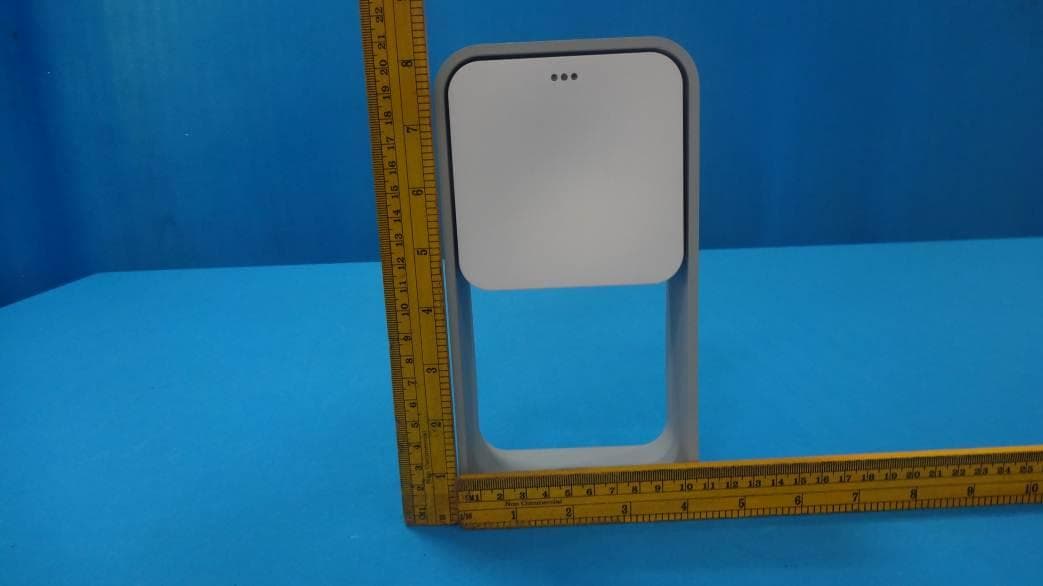
YAK22102
Jul 05, 2014S+ By ResMed
Equipment Class
DSS - Part 15 Spread Spectrum Transmitter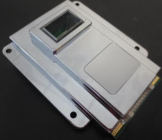
YAKBM14
Feb 16, 2014Field Disturbance Sensor
Equipment Class
FDS - Part 15 Field Disturbance Sensor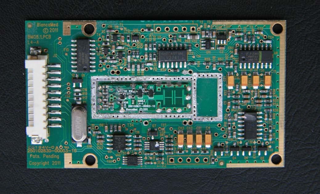
YAKBM11
Nov 01, 2011Sensor Module
Equipment Class
FDS - Part 15 Field Disturbance Sensor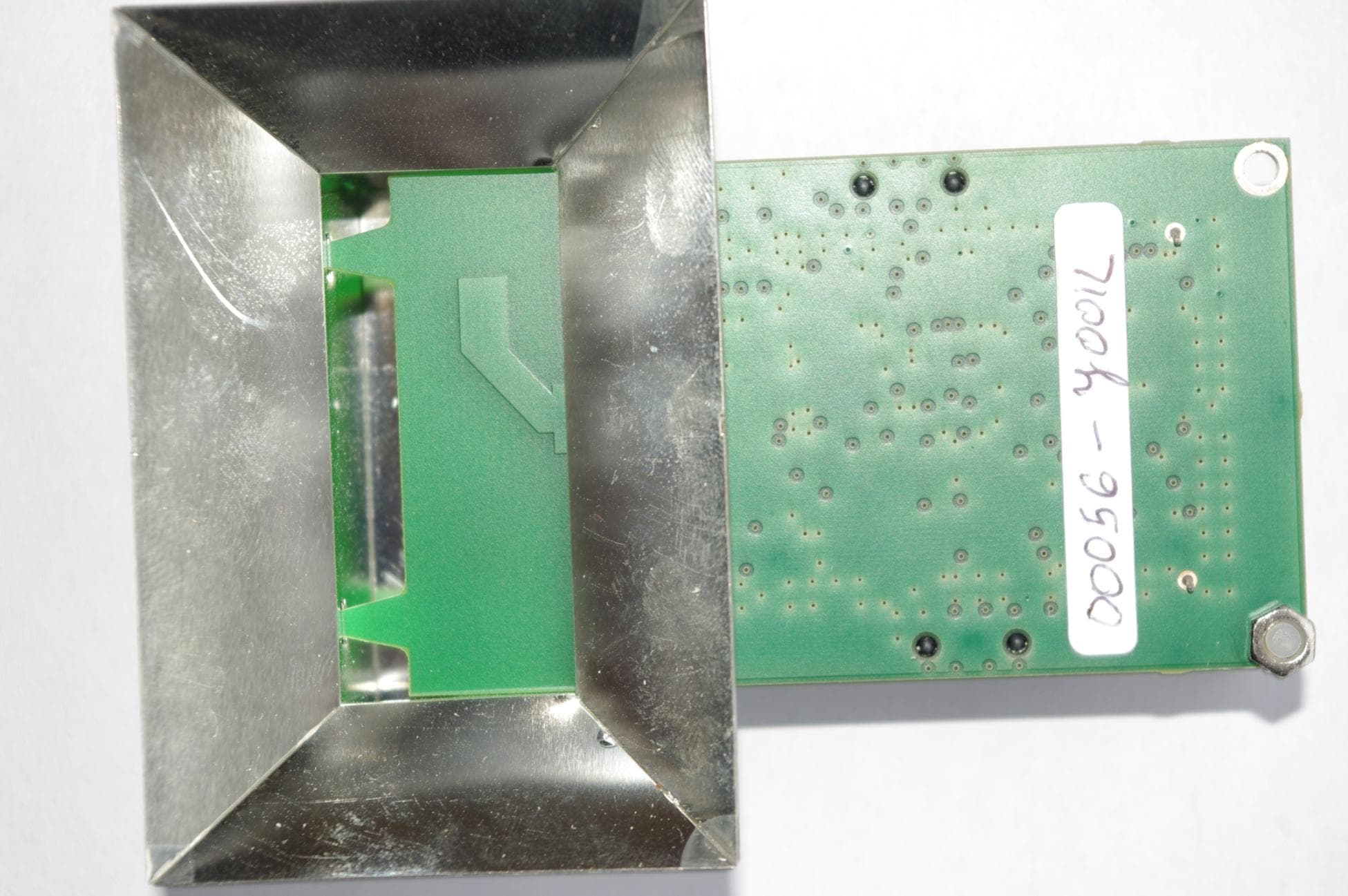
YAKBM04
May 05, 2010SleepMinder
Equipment Class
DXX - Part 15 Low Power Communication Device Transmitter