YAKBM04SleepMinder
Resmed Sensor Technologies Ltd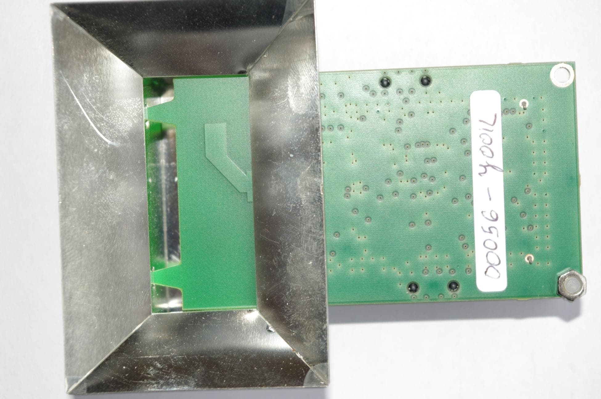
Click to zoom
Application Details
- Equipment Class
- DXX - Part 15 Low Power Communication Device Transmitter
- Date of Grant
- May 05, 2010
- Application Purpose
- Original Equipment
- Date of Application
- May 05, 2010
- Equipment Note
- SleepMinder
- Frequency Range
- 5800.00000000 - 5800.00000000
- Country
- Ireland
Documents & Files
Document Text
Text extracted from the exhibit documents filed with the FCC. Open a document above to read the original.
Users Manual
SleepMinder TM Non Contact Sleep Monitoring ABOUT THE SLEEPMINDER TM The SleepMinder TM uses a specially-designed motion sensor to detect body movement associated with sleeping. It can be used in the home, hospital or clinical setting. USING THE SLEEPMINDER TM 1 SleepMinder TM uses a removable standard Secure Digital (SD) memory card to store the data. Make sure the memory card is inserted in the slot and that the 'LOCK' tab on the SD card is set at unlocked. Push the SD card into the slot until you hear a click. If the card is flush with the casing, it is inserted correctly. 2 Insert the power connector from the 12V DC adaptor and turn it on at AC wall outlet. There is no power switch on the unit. 3 The small light on the rear will show green. There should be a single beep. This indicates that the unit is powered. 4 Put the SleepMinder TM on your side of the bed, at about an arm's length – 3ft (90cm) – from your chest. It is important that the front of the SleepMinder TM (indicated by the BiancaMed logo) is facing toward your chest as shown in the figure below. 5 Do not switch off the SleepMinder TM until you have finished the study – even if the study runs over a number of nights. • The base of the SleepMinder TM should be above the mattress, and up to a max 8” (20cm) higher. • The green light should face away from you. • Place at approximately an arm's length from you (or 3ft [90cm]) Warning • If SleepMinder TM is setup contrary to the operating conditions above it may produce misleading results. SCHEDULES The unit that you have been given may be set to start & stop automatically at particular times. A typical setup is that the unit will record between the hours of 9pm and 9am only, with the time set to your local time zone. When it is logging, you will see a green light constantly lit on the rear. If the green light flashes, the unit is not logging. All recorded data is saved on the memory card indefinitely. It can store over 1 year of data. TROUBLESHOOTING When I insert the memory card and power the device, the red light stays on or the red light flashes or the unit beeps three times. • This is a problem with the memory card. Power down the unit and wait 2 seconds. Push the memory card to release. Check the 'LOCK' tab on the memory card to make sure it is unlocked. Re-insert the memory card, pushing firmly until you hear a click. When I plug in the power cord, there is no green light on the SleepMinder TM at all. • This is a power problem. Check the AC wall outlet, and check the power adaptor (black unit) is showing a green light. For further support, please phone BiancaMed on +353 1716 3755 or email [email protected]. BiancaMed Limited, NovaUCD, Belfield Innovation Park, Belfield, Dublin 4, Ireland. Warnings • Never remove the SD-card while the unit is powered. If it is ever necessary to remove the SD-card, the unit must be powered down for 2 seconds before removal. • Do not use in close proximity (i.e., closer than 1 ft [30cm]) to wireless routers, laptops, mobile phones (especially do not put a mobile phone on your bedside table, beside/in front of the SleepMinder TM ). In addition, wireless phone handsets (often called DECT phones) should be kept 4m (14ft) if they are operating on 5.8GHz frequency. SleepMinder TM Unit Number Service Expiry Date Schedule FCC WARNING STATEMENT Note: This equipment has been tested and found to comply with the limits for a Class B digital device, pursuant to Part 15 of the FCC Rules. These limits are designed to provide reasonable protection against harmful interference in a residential installation. This equipment generates uses and can radiate radio frequency energy and, if not installed and used in accordance with the instructions, may cause harmful interference to radio communications. However, there is no guarantee that interference will not occur in a particular installation. If this equipment does cause harmful interference to radio or television reception, which can be determined by turning the equipment off and on, the user is encouraged to try to correct the interference by one of the following measures: Reorient or relocate the receiving antenna. Increase the separation between the equipment and receiver. Connect the equipment into an outlet on a circuit different from that to which the receiver is connected. Consult the dealer or an experienced radio/TV technician for help. This device complies with Part 15 of the FCC Rules. Operation is subject to the following two conditions: (1) This device may not cause harmful interference, and (2) this device must accept any interference received, including interference that may cause undesired operation. FCC Caution: Any changes or modifications not expressly approved by the party responsible for compliance could void the user's authority to operate this equipment. This device complies with FCC’s RF radiation exposure limits set forth for general population. It must be installed and operated to provide a separation distance of at least 20cm from all persons and must not be co-located or operating in conjunction with any other antenna or transmitter. BM04 SLEEPMINDER TM DEVICE INFORMATION System Description SleepMinder TM is a motion-recording system that uses a 5.8GHz motion sensor, logging to a Secure Digital memory card. It contains a real-time clock IC with internal battery and safe shutdown PP3 battery. It is intended for continuous operation during normal use. The SleepMinder TM System includes the following components: • 12V AC Adaptor (Friwo PP8 Medical 12V) • SleepMinder TM with SD memory card • SleepMinder TM carry case Warnings • Contains small parts that can be swallowed. Keep out of reach of children. • Read the instructions before using the SleepMinder TM unit. • Do not use in the presence of a flammable anesthetic mixture combined with air or with oxygen or nitrous oxide. • To avoid the risk of fire, do not use in the presence of flammable substances. • If the equipment is used in a…
Text truncated - open the document above for the full version.
External Photos
Report Ref: 10E2475-4 Exhibit B Page 1 of 21 Project Number: 10E2475-4 Prepared for: Biancamed Ltd By Compliance Engineering Ireland Ltd Ratoath Road Ashbourne Co. Meath FCC Site Registration: 92592 Industry Canada Assigned Code: 8517A Date 26 th April 2010 FCC EQUIPMENT AUTHORISATION Test Report EUT Description Motion Sensor Authorised: Report Ref: 10E2475-4 Exhibit B Page 2 of 21 Exhibit B – Photographs Report Ref: 10E2475-4 Exhibit B Page 3 of 21 Exhibit A – Technical Report Biancamed Ltd., Sleepminder Motion Sensor Applicant Name and Address The system covered under this authorisation report was designed, manufactured and assembled by Biancamed Ltd. The company's full name and mailing address is given below: BiancaMed Limited, NovaUCD, Belfield Innovation Park, Dublin 4, Ireland. Model Name The model number for the EUT covered under this application report is: Sleepminder Report Ref: 10E2475-4 Exhibit B Page 4 of 21 Figure 1: EUT on turntable Report Ref: 10E2475-4 Exhibit B Page 5 of 21 Figure 2: Turntable Report Ref: 10E2475-4 Exhibit B Page 6 of 21 Figure 3: Internal Front View Report Ref: 10E2475-4 Exhibit B Page 7 of 21 Figure 4: Removed from enclosure Report Ref: 10E2475-4 Exhibit B Page 8 of 21 Figure 5: Disassembled view Report Ref: 10E2475-4 Exhibit B Page 9 of 21 Figure 6: Rear view of antenna module Report Ref: 10E2475-4 Exhibit B Page 10 of 21 Figure 7: Main PCB Report Ref: 10E2475-4 Exhibit B Page 11 of 21 Figure 8: Top View Main PCB FCC ID: QOQWT11 Module Report Ref: 10E2475-4 Exhibit B Page 12 of 21 Figure 9: View of 5.8 GHz transmitter assembly with cover removed Report Ref: 10E2475-4 Exhibit B Page 13 of 21 Figure 10: Front view of Transmitter Module Report Ref: 10E2475-4 Exhibit B Page 14 of 21 Figure 11: Side View of transmitter module Report Ref: 10E2475-4 Exhibit B Page 15 of 21 Figure 12: Side View of transmitter Module Report Ref: 10E2475-4 Exhibit B Page 16 of 21 Figure 13: Rear view of Enclosure Report Ref: 10E2475-4 Exhibit B Page 17 of 21 Figure 14: Side View of Enclosure Report Ref: 10E2475-4 Exhibit B Page 18 of 21 Figure 15: Bottom View of Enclosure Report Ref: 10E2475-4 Exhibit B Page 19 of 21 Figure 16: Top view of Enclosure Report Ref: 10E2475-4 Exhibit B Page 20 of 21 Figure 17: Side view of Enclosure Report Ref: 10E2475-4 Exhibit B Page 21 of 21 Figure 18: Power supply
ID Label/Location Info
BiancaMed BM-04 Product conforms to EN 60601-1-2 EN 60601-1:1990 12V DC 100mA This equipment includes FCC ID: QOQWT11 BiancaMed LIMITED Confidential Doc. BM04.3DOC Title SleepMinder Device Rear Label Revision Date Nature of revision Author FCC ID: YAKBM04 This device complies with part 15 of the FCC Rules. Operation is subject to the following two conditions: (1) This device may not cause harmful interference, and (2) this device must accept any interference received, including interference that may cause undesired operation BiancaMed Limited Tel: +353 1 716 3799 Fax: +353 1 716 3709 Website: www.biancamed.com BiancaMed Limited, Registered in Ireland No: 372477 Address: BiancaMed, NovaUCD, University College Dublin, Belfield, Dublin 4, Ireland Label Location
Internal Photos
Report Ref: 10E2475-4 Exhibit B Page 1 of 21 Project Number: 10E2475-4 Prepared for: Biancamed Ltd By Compliance Engineering Ireland Ltd Ratoath Road Ashbourne Co. Meath FCC Site Registration: 92592 Industry Canada Assigned Code: 8517A Date 26 th April 2010 FCC EQUIPMENT AUTHORISATION Test Report EUT Description Motion Sensor Authorised: Report Ref: 10E2475-4 Exhibit B Page 2 of 21 Exhibit B – Photographs Report Ref: 10E2475-4 Exhibit B Page 3 of 21 Exhibit A – Technical Report Biancamed Ltd., Sleepminder Motion Sensor Applicant Name and Address The system covered under this authorisation report was designed, manufactured and assembled by Biancamed Ltd. The company's full name and mailing address is given below: BiancaMed Limited, NovaUCD, Belfield Innovation Park, Dublin 4, Ireland. Model Name The model number for the EUT covered under this application report is: Sleepminder Report Ref: 10E2475-4 Exhibit B Page 4 of 21 Figure 1: EUT on turntable Report Ref: 10E2475-4 Exhibit B Page 5 of 21 Figure 2: Turntable Report Ref: 10E2475-4 Exhibit B Page 6 of 21 Figure 3: Internal Front View Report Ref: 10E2475-4 Exhibit B Page 7 of 21 Figure 4: Removed from enclosure Report Ref: 10E2475-4 Exhibit B Page 8 of 21 Figure 5: Disassembled view Report Ref: 10E2475-4 Exhibit B Page 9 of 21 Figure 6: Rear view of antenna module Report Ref: 10E2475-4 Exhibit B Page 10 of 21 Figure 7: Main PCB Report Ref: 10E2475-4 Exhibit B Page 11 of 21 Figure 8: Top View Main PCB FCC ID: QOQWT11 Module Report Ref: 10E2475-4 Exhibit B Page 12 of 21 Figure 9: View of 5.8 GHz transmitter assembly with cover removed Report Ref: 10E2475-4 Exhibit B Page 13 of 21 Figure 10: Front view of Transmitter Module Report Ref: 10E2475-4 Exhibit B Page 14 of 21 Figure 11: Side View of transmitter module Report Ref: 10E2475-4 Exhibit B Page 15 of 21 Figure 12: Side View of transmitter Module Report Ref: 10E2475-4 Exhibit B Page 16 of 21 Figure 13: Rear view of Enclosure Report Ref: 10E2475-4 Exhibit B Page 17 of 21 Figure 14: Side View of Enclosure Report Ref: 10E2475-4 Exhibit B Page 18 of 21 Figure 15: Bottom View of Enclosure Report Ref: 10E2475-4 Exhibit B Page 19 of 21 Figure 16: Top view of Enclosure Report Ref: 10E2475-4 Exhibit B Page 20 of 21 Figure 17: Side view of Enclosure Report Ref: 10E2475-4 Exhibit B Page 21 of 21 Figure 18: Power supply
RF Exposure Info
The BiancaMed Sleep Monitor includes a Bluetooth module with FCC ID: QOQWT11. Sleep Monitor (5.8GHz) Peak field strength = 67.3dBuV/m at 3m = -27.93dBm EIRP Power density at 20cm = 0.000001 mW/cm2 (Limit 1 mW/cm2 at 20cm) Bluetooth module (2.4GHz) Conducted output power = 13.47dBm Antenna Gain = 0dBi Power density at 20cm = 0.004423 mW/cm2 (Limit 1 mW/cm2 at 20cm) PD1 = Power density of 1 st transmitter PD2 = Power density of 2 nd transmitter L1 = Power density limit for 1 st transmitter L2 = Power density limit for 2 nd transmitter Requirement PD1/L1 + PD2/L2 < 1 0.000001/1 + 0.004423/1 < 1 0.004424 < 1 Therefore device complies with FCC RF radiation exposure limits for general population as a mobile device (d > 20cm).
Test Report
Report Ref: 10E2475-5 Page 1 of 27 Project Number: 10E2475-5 Prepared for: Biancamed Ltd By Compliance Engineering Ireland Ltd Ratoath Road Ashbourne Co. Meath FCC Site Registration: 92592 Industry Canada Assigned Code: 8517A Date 4 th May 2010 FCC EQUIPMENT AUTHORISATION Test Report EUT Description Motion Sensor Authorised: Compliance Engineering Ireland Ltd RAYSTOWN, RATOATH ROAD, ASHBOURNE, CO. MEATH, IRELAND Tel: +353 1 8256722 Fax: +353 1 8256733 Report Ref: 10E2475-5 Page 2 of 27 List of Exhibits Title Page List of Exhibits Exhibit A – Technical Report Exhibit B – Photographs THIS REPORT SHALL NOT BE REPRODUCED EXCEPT IN FULL, WITHOUT THE WRITTEN APPROVAL OF COMPLIANCE ENGINEERING IRELAND LTD Report Ref: 10E2475-5 Page 3 of 27 Exhibit A – Technical Report Biancamed Ltd., Sleepminder Motion Sensor Applicant Name and Address The system covered under this authorisation report was designed, manufactured and assembled by Biancamed Ltd. The company's full name and mailing address is given below: BiancaMed Limited, NovaUCD, Belfield Innovation Park, Dublin 4, Ireland. Model Name The model number for the EUT covered under this application report is: Sleepminder Report Ref: 10E2475-5 Page 4 of 27 Description of Equipment The EUT was a motion detector using a short range 5.8 GHz transceiver to detect motion, intended for use in clinical sleep trials in the volunteers’ own home. Events were logged to a data card, which could later be analyzed on a computer using a custom algorithm to distinguish chest movement from background motion (not supplied by the manufacturer during testing). Equipment Details Brand Name: Sleepminder Manufacturer: BiancaMed Description: 5.8 GHz motion detector Manufacturer: Friwo Description: PSU Model Number: FW7333SM/12 Modifications Several modifications were required in order to pass the radiated emissions test specification: A Würth Elektronik ferrite, Model No: 742 711 4, was placed on the DC supply cable (See Figure 1 following) Operating Conditions during Test: Normal Scanning Report Ref: 10E2475-5 Page 5 of 27 Table of Contents APPLICANT NAME AND ADDRESS ........................................................................................................................... 3 MODEL NAME ........................................................................................................................................................ 3 DESCRIPTION OF EQUIPMENT ................................................................................................................................ 4 1.0 EUT DESCRIPTION ......................................................................................................................................... 6 1.1 1.1 EUT OPERATION ...................................................................................................................................... 6 1.2 MODIFICATIONS ............................................................................................................................................ 6 1.3 DATE OF TEST ................................................................................................................................................ 6 2.0 ELECTROMAGNETIC EMISSIONS TESTING ....................................................................................................... 7 2.1.1 MEASUREMENT UNCERTAINTY ................................................................................................................. 7 2.2 TEST CRITERIA ............................................................................................................................................... 7 2.3 CONDUCTED EMISSIONS MEASUREMENTS .................................................................................................... 7 2.3.1 TEST PROCEDURE ...................................................................................................................................... 7 3.0 RADIATED EMISSIONS MEASUREMENTS ........................................................................................................ 8 3.1 TEST PROCEDURE .......................................................................................................................................... 8 3.2 TEST CRITERIA ............................................................................................................................................... 8 4.0 FIELD STRENGTH OF FUNDAMENTAL ............................................................................................................. 9 4.1 TEST DATA – FIELD STRENGTH OF FUNDAMENTAL ......................................................................................... 9 5.0 FIELD STRENGTH OF HARMONICS ................................................................................................................ 11 6.0 FIELD STRENGTH OF SPURIOUS RADIATED EMISSIONS ................................................................................. 11 7.0 LIST OF TEST EQUIPMENT ............................................................................................................................ 12 Report Ref: 10E2475-5 Page 6 of 27 1.0 EUT Description The EUT was a motion detector using a short range 5.8 GHz transceiver to detect motion, intended for use in clinical sleep trials in the volunteers’ own home. Events were logged to a data card, which could later be analyzed on a computer using a custom algorithm to distinguish chest movement from background motion (not supplied by the manufacturer during testing). 1.1 1.1 EUT Operation The EUT was tested in normal scanning mode. 1.2 Modifications Figure 1: Location of Ferrite 742 711 4 1.3 Date of Test The tests were carried out on one sample of the EUT on the 14 th of February 2010 and additional pulse width measurements on 26 April 2010. Report Ref: 10E2475-5 Page 7 of 27 2.0 Electromagnetic Emissions Testing The guidelines of CISPR 16-4 were used for all uncertainty calculation…
Text truncated - open the document above for the full version.
Test Setup Photos
Report Ref: 10E2475-4 Exhibit B Page 4 of 21 Figure 1: EUT on turntable Report Ref: 10E2475-4 Exhibit B Page 5 of 21 Figure 2: Turntable Report Ref: 10E2475-4 Page 27 of 27 Exhibit B Test Configurations Figure 1: Radiated emissions setup on open area site Figure 2: Conducted Emissions setup
Contact Information
Applicant
Michael Wren(Product Development Manager)
Test Firm
Compliance Engineering Ireland Ltd.John McAuley
Technical Specifications
| # | Rule Parts | Frequency Range | Power Output |
|---|---|---|---|
| 1 | 15C | 5.80 GHz - 5.80 GHz | - |
Other Applications from Resmed Sensor Technologies Ltd
YAK22102
Jul 05, 2014S+ By ResMed
Equipment Class
DSS - Part 15 Spread Spectrum Transmitter
YAKBM14
Feb 16, 2014Field Disturbance Sensor
Equipment Class
FDS - Part 15 Field Disturbance Sensor
YAKBM11
Nov 01, 2011Sensor Module
Equipment Class
FDS - Part 15 Field Disturbance Sensor
YAKBM08
Mar 01, 2011Motion Detector Module
Equipment Class
FDS - Part 15 Field Disturbance Sensor