YCP-MB1355002MB1355D-01
STMicroelectronics (Rousset) SAS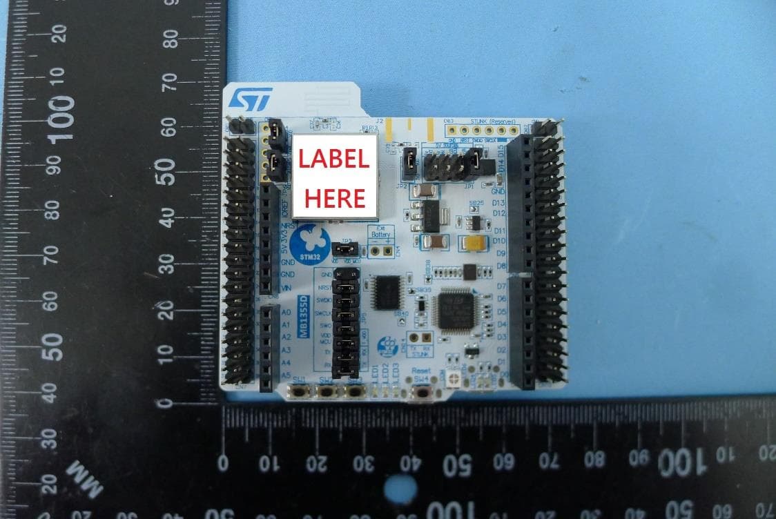
Click to zoom
Application Details
- Equipment Class
- DTS - Digital Transmission System
- Date of Grant
- Apr 06, 2022
- Application Purpose
- Original Equipment
- Date of Application
- Mar 24, 2022
- Equipment Note
- MB1355D-01
- Frequency Range
- 2402.00000000 - 2480.00000000
- Country
- France
Documents & Files
Document Text
Text extracted from the exhibit documents filed with the FCC. Open a document above to read the original.
Users Manual
UM2819 User manual STM32WB Nucleo-64 board (MB1355) Introduction The NUCLEO-WB55RG STM32WB Nucleo-64 board based on the MB1355 board is a Bluetooth ® Low Energy wireless and ultra-low-power device embedding a powerful and ultra-low-power radio compliant with the Bluetooth ® Low Energy SIG specification v5.2 and IEEE802.15.4-2011 PHY and MAC is supported. The ARDUINO ® Uno V3 connectivity support and the ST morpho headers provide an easy means of expanding the functionality of the STM32WB Nucleo open development platform with a wide choice of specialized shields. Figure 1. NUCLEO-WB55RG top view Picture is not contractual. UM2819 - Rev 1 – March 2022 For further information contact your local STMicroelectronics sales office. www.st.com UM2819 UM2819 - Rev 1 page 2/37 Features 1 Features • STM32WB55RG (1-Mbytes Flash memory, 256-Kbyte SRAM, in VFQFPN68 package) ultra‑low‑power wireless microcontroller featuring: – Dual-core 32‑bit (Arm ® Cortex ® -M4 and dedicated M0+ CPU for real-time radio layer) – 2.4 GHz RF transceiver supporting Bluetooth ® specification v5.2 • Three user LEDs • One reset and three user push-buttons • Board connectors: – ARDUINO ® Uno V3 expansion connector – ST morpho extension pin headers for full access to all STM32WB I/Os • Integrated PCB antenna and SMA connector footprint • Flexible power-supply options: ST-LINK, USB V BUS , or external sources • On-board footprint to mount a CR2032 battery socket • On-board ST-LINK/V2-1 debugger/programmer with USB re-enumeration capability: mass storage, Virtual COM port, and debug port • Comprehensive free software libraries and examples available with the STM32CubeWB MCU Package • Support of a wide choice of Integrated Development Environments (IDEs) including IAR Embedded Workbench ® , MDK-ARM, STM32CubeIDE Note: Arm is a registered trademark of Arm Limited (or its subsidiaries) in the US and/or elsewhere. vd UM2819 UM2819 - Rev 1 page 3/37 Ordering information 2 Ordering information To order the NUCLEO-WB55RG Nucleo-64 board, refer to Table 1. Additional information is available from the datasheet and reference manual of the target STM32. Table 1. Ordering information Order code Board reference Target STM32 NUCLEO-WB55RG MB1355 STM32WB55RG 2.1 Codification The meaning of the codification is explained in Table 2. Table 2. Codification explanation NUCLEO-XXRYTZ Description Example: NUCLEO-WB55RG XX MCU series in STM32 32-bit Arm Cortex MCUs Wireless Bluetooth ® STM32WB Series Y Product line in the Series STM32WBx5 product line R Product‑specific in the product line: • 1: Die 1, full set of features STM32WB55 MCU family T STM32 package pin count: • R for 68 pins 68‑pin package Z STM32 Flash memory size: • G for 1 Mbytes 1‑Mbyte Flash memory UM2819 UM2819 - Rev 1 page 4/37 Development environment 3 Development environment 3.1 System requirements • Multi‑OS support: Windows ® 10, Linux ® 64-bit, or macOS ® • USB Type-A or USB Type-C ® to Micro-B cable Note: macOS ® is a trademark of Apple Inc. registered in the U.S. and other countries. Linux ® is a registered trademark of Linus Torvalds. All other trademarks are the property of their respective owners. 3.2 Development toolchains • IAR Systems ® - IAR Embedded Workbench ®(1) • Keil ® - MDK-ARM (1) • STMicroelectronics - STM32CubeIDE 1. On Windows ® only. 3.3 Demonstration software The demonstration software, included in the STM32Cube MCU Package corresponding to the on-board microcontroller, is preloaded in the STM32 Flash memory for easy demonstration of the device peripherals in standalone mode. The latest versions of the demonstration source code and associated documentation can be downloaded from www.st.com. UM2819 UM2819 - Rev 1 page 5/37 Conventions 4 Conventions Table 3 provides the conventions used for the ON and OFF settings in the present document. Table 3. ON/OFF convention Convention Definition Jumper JPx ON Jumper fitted Jumper JPx OFF Jumper not fitted Jumper JPx [1-2] Jumper fitted between Pin 1 and Pin 2 Solder bridge SBx ON SBx connections closed by 0 Ω resistor Solder bridge SBx OFF SBx connections left open Resistor Rx ON Resistor soldered Resistor Rx OFF Resistor not soldered UM2819 UM2819 - Rev 1 page 6/37 Safety recommendations 5 Safety recommendations 5.1 Targeted audience This product targets users with at least basic electronics or embedded software development knowledge such as engineers, technicians, or students. This board is not a toy and is not suited for use by children. 5.2 Handling the board This product contains a bare printed circuit board and like all products of this type, the user must be careful about the following points: • The connection pins on the board may be sharp, be careful when handling the board to avoid hurting yourself • This board contains static sensitive devices. To avoid damaging it, handle the board in an ESD‑proof environment. • While powered, do not touch the electric connections on the board with your fingers or anything conductive. The board operates at a voltage level that is not dangerous, but components may be damaged when shorted. • Do not put any liquid on the board and avoid operating the board close to water or at a high humidity level. • Do not operate the board if dirty or dusty. UM2819 UM2819 - Rev 1 page 7/37 Quick start 6 Quick start This section describes how to quickly start development using NUCLEO-WB55RG. To use the product, the user must accept the Evaluation Product License Agreement from the www.st.com/ epla webpage. For more information on the STM32WB Nucleo-64 board and demonstration software, visit the www.st.com/stm32nucleo webpage. Before the first use, make sure that no damage has occurred to the board during shipment: • All socketed components must be firmly secured in their sockets. • Nothing must be loose in the board blister. The Nucleo board is an easy-to-use development kit to quickly evaluate and start development with an STM32 microcontroller in a QFN48 package. 6.1 Getting started Foll…
Text truncated - open the document above for the full version.
Cover Letter(s)
STMicroelectronics. 190 Avenue Celestin Coq, CS 60004, 13016 Rousset Cedex, France RF_160, Issue 04 Declaration of Authorization We Name: STMICROELECTRONICS Address: 190 Avenue Celestin Coq, CS 60004 City: 13016 Rousset Cedex Country: FRANCE Declare that: Name Representative of agent: Chenz Ker (1) Agent Company name: MRT Technology(Taiwan) Co., Ltd Address: NO.38, Fuxing 2nd Rd., Guishan Dist., Taoyuan City 33377 ,Taiwan(R.O.C) City: Taoyuan City Country Taiwan is authorized to apply for Certification of the following product(s): Product description: NUCLEO64 for STM32WB55RG Type designation: MB1355D-01 Trademark: STMICROELECTRONICS. Validity/ expiry date 04/03/2027 FCC ID: YCP-MB1355002 on our behalf. Date: 04/03/2022 City: ROUSSET/ FRANCE Name: Joel HULOUX (2) Function: MDG/MMS STRATEGIC PLANNING Signature: Notes: (1): Required for FCC application (2): For FCC it must be the Grantee Code “owner” or the authorized agent.
Cover Letter(s)
FCC, Request for non-disclosure Date: 19-Oct-10 RF_501, Issue 7 Page 1 of 1 Company Name: STMICROELECTRONICS Address: 190 Avenue Celestin Coq, CS 60004 City: 13016 Rousset Cedex Country: FRANCE To: Telefication B.V., Dept. FCC TCB Edisonstraat 12A 6902 PK ZEVENAAR The Netherlands Subject: Request for confidentiality FCC ID: YCP-MB1355002 Reference number: ###### Dear FCC TCB, 1. Long-Term Confidentiality Pursuant to 47 CFR Section 0.459(a) & (b), we hereby requests non-disclosure and confidential treatment of the following materials submitted in support of FCC certification application: Bill(s) of Material Block Diagrams Operational Description Schematic Diagrams Tune-up Procedure Above materials contain secrets, proprietary and technical information, which would customarily be guarded from competitors under 47 CFR, section 0.457(d)(2). Disclosure or publication or any portion of this company confidential material to other parties could cause substantial competitive harm and provide unjustified benefits for competitors. 2. Short-Term Confidentiality (STC) Pursuant to Public Notice DA 04-1705 of the Commission’s policy, in order to comply with the marketing regulations in 47 CFR §2.803 and the importation rules in 47 CFR §2.1204, applicant hereby requests Short-Term Confidential treatment of the following materials (note 1): Internal Photos User’s Manual Test Set-up Photos External Photos Justification: Planned Release Date STC: (notes 2, 3, 4, 5). If no date is given, 45 days from grant date will be used. Date: 16 th of March 2022 Name and signature of applicant: Joel HULOUX Notes: 1) A document or type of document can only have ONE type of confidentiality! 2) Short-Term confidentiality is in principle for 45 days from date of grant; it can be extended max 3 times (total time 180 days max.)! 3) FCC must be informed when marketing begins earlier. 4) Release takes place automatically thus extension must be requested in time. Telefication does not remind you of this! 5) Request for extension or for release must be received by Telefication at least 7 days before date of actual marketing or before expiration of the STC period
External Photos
Report No.: 2112TW5402-U2 Product: NUCLEO64 for STM32WB55RG Brand Name: STMICROELECTRONICS Model Number: MB1355D-01 1 of 3 External Photograph (1) EUT Photo (2) EUT Photo Report No.: 2112TW5402-U2 2 of 3 (3) EUT Photo (4) EUT Photo Report No.: 2112TW5402-U2 3 of 3 (5) EUT Photo (6) EUT Photo
ID Label/Location Info
16mm 16mm Board Ref(«MB1355») & PCB version («D»)
Internal Photos
Report No.: 2112TW5402-U2 Product: NUCLEO64 for STM32WB55RG Brand Name: STMICROELECTRONICS Model Number: MB1355D-01 1 of 3 Internal Photograph (1) EUT Photo (2) EUT Photo Report No.: 2112TW5402-U2 2 of 3 (3) EUT Photo (4) EUT Photo Report No.: 2112TW5402-U2 3 of 3 (5) EUT Photo
RF Exposure Info
MRT Technology (Taiwan) Co., Ltd Report No.: 2112TW5402-U2 Phone: +886-3-3288388 Report Version: 1.0 Fax: +886-3-3288918 Issue Date: 2022-01-26 Web: www.mrt-cert.com FCC ID: 2AABGQ4020-1M Page Number: 1 of 6 IC: 25041-Q40201M RF Exposure Evaluation Declaration FCC ID: YCP-MB1355002 IC: 8976A-MB1355002 APPLICANT: STMicroelectronics SAS Application Type: Certification Product: NUCLEO64 for STM32WB55RG Model No.: MB1355D-01 Brand Name: STMICROELECTRONICS FCC Rule Part(s): Part 2.1091 (Mobile) ISED Standard: RSS 102 (issue5) Test Procedure(s): KDB 447498 D01v06 Test Date: January 9 ,2022 Reviewed By : ( Paddy Chen ) Approved By : ( Chenz Ker ) The test results relate only to the samples tested. This equipment has been shown to be capable of compliance with the applicable technical standards as indicated in the measurement report. Test results reported herein relate only to the item(s) tested. The test report shall not be reproduced except in full without the written approval of MRT Technology (Taiwan) Co., Ltd. Report No.: 2112TW5402-U2 FCC ID: 2AABGQ4020-1M Page Number: 2 of 6 IC: 25041-Q40201M Revision History Report No. Version Description Issue Date Note 2112TW5402-U2 1.0 Original Report 2022-01-26 Report No.: 2112TW5402-U2 FCC ID: 2AABGQ4020-1M Page Number: 3 of 6 IC: 25041-Q40201M 1. PRODUCT INFORMATION 1.1. Equipment Description 1.2. Antenna Description No. Manufacturer Part No. Antenna Type Peak Gain 1 STMICROELECTRONICS AN5129 PCB 1.95dBi Product Name NUCLEO64 for STM32WB55RG Model No. MB1355D-01 Brand Name STMICROELECTRONICS Bluetooth Specification V5.2 LE Operating Frequency 2402~2480MHz Modulation Type GFSK Report No.: 2112TW5402-U2 FCC ID: 2AABGQ4020-1M Page Number: 4 of 6 IC: 25041-Q40201M 2. MAXIMUM PERMISSIBLE EXPOSURE (MPE) 2.1. Limits According to FCC 1.1310: The criteria listed in the following table shall be used to evaluate the environment impact of human exposure to radio frequency (RF) radiation as specified in 1.1307(b) LIMITS FOR MAXIMUM PERMISSIBLE EXPOSURE (MPE) Frequency Range (MHz) Electric Field Strength (V/m) Magnetic Field Strength (A/m) Power Density (mW/cm 2 ) Average Time (Minutes) (A) Limits for Occupational/ Control Exposures 0.3-3.0 614 1.63 *100 6 3.0-30 1842/f 4.89/f *900/f 2 6 30-300 61.4 0.163 1.0 6 300-1500 -- -- f/300 6 1500-100,000 -- -- 5 6 (B) Limits for General Population/ Uncontrolled Exposures 0.3-1.4 614 1.63 *100 30 1.34-30 824/f 2.19/f *180/f 2 30 30-300 27.5 0.073 0.2 30 300-1500 -- -- f/1500 30 1500-100,000 -- -- 1.0 30 Note : (1) f= Frequency in MHz , (2) * = Plane-wave equivalent power density Calculation Formula: Pd = (Pout*G)/(4*pi*r 2 ) Where Pd = power density in mW/cm 2 Pout = output power to antenna in mW G = gain of antenna in linear scale Pi = 3.1416 r = distance between observation point and center of the radiator in cm Under normal use condition, is at least 20cm away from the body of the user . So, this device is classified as Mobile Device. Report No.: 2112TW5402-U2 FCC ID: 2AABGQ4020-1M Page Number: 5 of 6 IC: 25041-Q40201M 2.2. ISED Limits According to RSS 102 issue 2: RF exposure evaluation is required if the separation distance between the user and/or bystander and the device’s radiating element is greater than 20 cm, except when the device operates as follows: • below 20 MHz and the source-based, time-averaged maximum e.i.r.p. of the device is equal to or less than 1 W (adjusted for tune-up tolerance); • at or above 20 MHz and below 48 MHz and the source-based, time-averaged maximum e.i.r.p. of the device is equal to or less than 4.49/ƒ 0.5 W (adjusted for tune-up tolerance), where ƒ is in MHz; • at or above 48 MHz and below 300 MHz and the source-based, time-averaged maximum e.i.r.p. of the device is equal to or less than 0.6 W (adjusted for tune-up tolerance); • at or above 300 MHz and below 6 GHz and the source-based, time-averaged maximum e.i.r.p. of the device is equal to or less than 1.31 x 10 -2 ƒ 0.6834 W (adjusted for tune-up tolerance), where ƒ is in MHz; • at or above 6 GHz and the source-based, time-averaged maximum e.i.r.p. of the device is equal to or less than 5 W (adjusted for tune-up tolerance). Report No.: 2112TW5402-U2 FCC ID: 2AABGQ4020-1M Page Number: 6 of 6 IC: 25041-Q40201M 2.3. Test Result FCC Mode Frequency (MHz) Output Power to Antenna (dBm) Output Power to Antenna (mW) Antenna Gain (dBi) Distance (cm) Power Density (mW/cm 2 ) Limit (mW/cm 2 ) BLE 2402~2480 -1.814 0.66 1.95 20 0.0002 1 ISED Mode Frequency Band (MHz) Output Power (dBm) Antenna Gain (dBi) Distance (cm) Source based, time-averaged maximum e.i.r.p. (dBm) Source based, time-averaged maximum e.i.r.p. (mW) Exemption Limits for Routine Evaluation (W) BLE 2402~2480 -1.814 1.95 20 0.136 1.03 5.35 So, this device can complies the SAR test exclusion. The End
Test Report
MRT Technology (Taiwan) Co., Ltd Report No.: 2112TW5402-U1 Phone: +886-3-3288388 Report Version: 1.0 Fax: +886-3-3288918 Issue Date: 2022-01-26 Web: www.mrt-cert.com FCC ID: YCP-MB1355002 Page Number: 1 of 70 IC: 8976A-MB1355002 FCC ID: YCP-MB1355002 IC: 8976A-MB1355002 APPLICANT: STMicroelectronics SAS Application Type: Certification Product: NUCLEO64 for STM32WB55RG Model No.: MB1355D-01 FCC Classification: (DTS) Digital Transmission System FCC Rule Part(s): Part 15.247 ISED Standard: RSS-247 Issue 2 Test Procedure(s): ANSI C63.10-2013 Received Date: December 27 ,2021 Test Date: January 6~8 ,2022 MEASUREMENT REPORT The test results only relate to the tested sample. This equipment has been shown to be capable of compliance with the applicable technical standards as indicated in the measurement report and was tested in accordance with the measurement procedures specified in ANSI C63.10. Test results reported herein relate only to the item(s) tested. The test report shall not be reproduced except in full without the written approval of MRT Technology (Taiwan) Co., Ltd. Tested By : ( Peter Syu ) Reviewed By : ( Paddy Chen ) Approved By : ( Chenz Ker) Report No.: 2112TW5402-U1 FCC ID: YCP-MB1355002 Page Number: 2 of 70 IC: 8976A-MB1355002 Revision History Report No. Version Description Issue Date Note 2112TW5402-U1 1.0 Original Report 2022-01-26 Report No.: 2112TW5402-U1 FCC ID: YCP-MB1355002 Page Number: 3 of 70 IC: 8976A-MB1355002 CONTENTS Description Page §2.1033 General Information ......................................................................................................... 5 1. INTRODUCTION ..................................................................................................................... 6 1.1. Scope .................................................................................................................................... 6 1.2. MRT Test Location ................................................................................................................ 6 2. PRODUCT INFORMATION ..................................................................................................... 7 2.1. Equipment Description .......................................................................................................... 7 2.2. Product Specification Subjective to this Standard .................................................................. 8 2.3. Test Mode ............................................................................................................................. 8 2.4. Operation Frequency / Channel List ...................................................................................... 9 2.5. Test Configuration ............................................................................................................... 10 2.6. Test Software ...................................................................................................................... 10 2.7. EMI Suppression Device(s)/Modifications ........................................................................... 10 2.8. Labeling Requirements ....................................................................................................... 10 3. DESCRIPTION of TEST ......................................................................................................... 11 3.1. Evaluation Procedure .......................................................................................................... 11 3.2. AC Line Conducted Emissions ............................................................................................ 11 3.3. Radiated Emissions ............................................................................................................ 12 4. ANTENNA REQUIREMENTS ................................................................................................ 13 5. TEST EQUIPMENT CALIBRATION DATE ............................................................................ 14 6. MEASUREMENT UNCERTAINTY ......................................................................................... 15 7. TEST RESULT ...................................................................................................................... 16 7.1. Summary ............................................................................................................................. 16 7.2. Occupied Bandwidth Measurement ..................................................................................... 17 7.2.1. Test Limit ......................................................................................................................... 17 7.2.2. Test Procedure used ....................................................................................................... 17 7.2.3. Test Setting ..................................................................................................................... 17 7.2.4. Test Setup ....................................................................................................................... 17 7.2.5. Test Result ...................................................................................................................... 18 7.3. Output Power Measurement ................................................................................................ 21 7.3.1. Test Limit ......................................................................................................................... 21 7.3.2. Test Procedure Used ....................................................................................................... 21 7.3.3. Test Setting ..................................................................................................................... 21 7.3.4. Test Setup ....................................................................................................................... 21 7.3.5. Test Result of Output Power ...............................................…
Text truncated - open the document above for the full version.
Test Setup Photos
Report No.: 2112TW5402-U2 Product: NUCLEO64 for STM32WB55RG Brand Name: STMICROELECTRONICS Model Number: MB1355D-01 1 of 3 Test Photograph Description: Front View of Conducted Emission Test Setup Description: Back View of Conducted Emission Test Setup Report No.: 2112TW5402-U2 2 of 3 Description: Radiated Emission Test Setup for below 1GHz Description: Radiated Emission Test Setup for above 1GHz Report No.: 2112TW5402-U2 3 of 3 Description: Conducted Emission Test Setup
Contact Information
Applicant
PASCAL SCAFIDI(MDG Group VP Quality & Reliability)
Technical Contact
MRT Technology (Taiwan) Co., LtdChenz Ker
[email protected]886-3-3288388
No. 38, Fuxing Second Rd., Guishan Dist., · Taiwan
Non-Technical Contact
MRT Technology (Taiwan) Co., LtdChenz Ker
[email protected]886-3-3288388
Test Firm
MRT Technology (Taiwan) Co.,LtdChenz Ker
Technical Specifications
| # | Rule Parts | Frequency Range | Power Output |
|---|---|---|---|
| 1 | 15C | 2.40 GHz - 2.48 GHz | 700.00 µW |
Other Applications from STMicroelectronics (Rousset) SAS
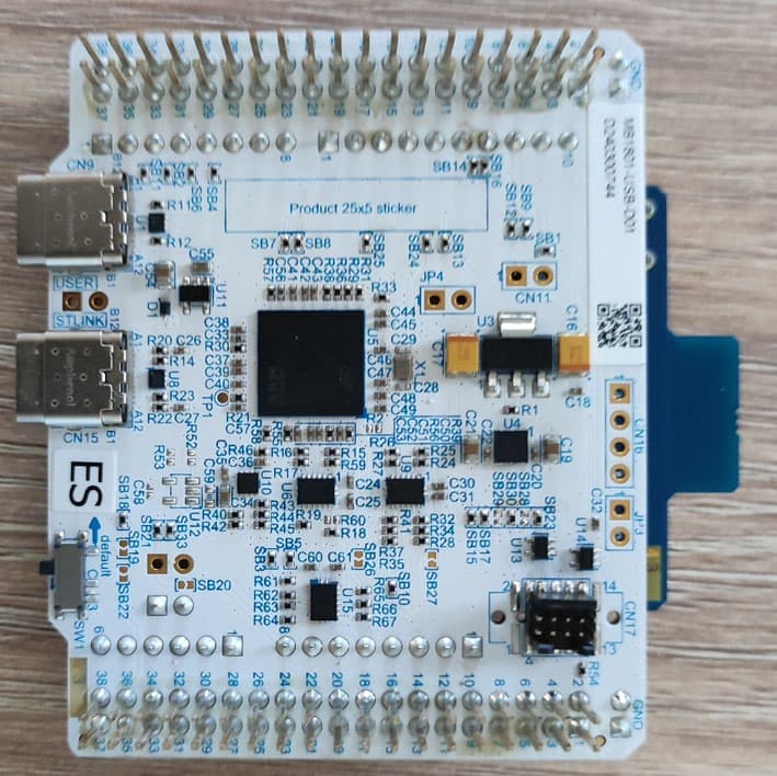
YCP-MB229300
Jun 08, 2026BLE RF evaluation board
Equipment Class
DTS - Digital Transmission System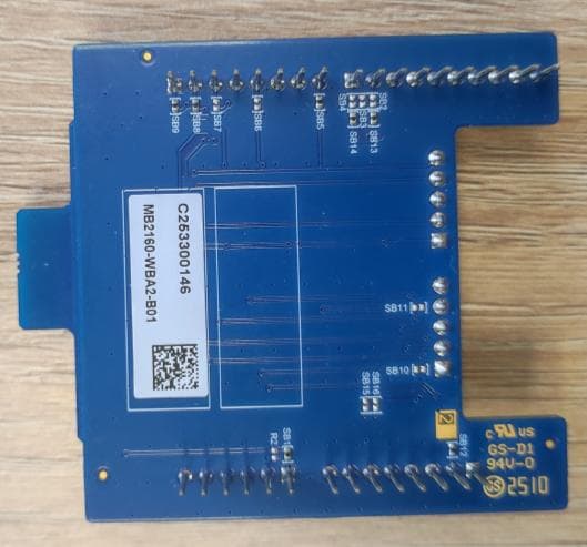
YCP-MB229301
Jun 08, 2026BLE RF evaluation board
Equipment Class
DTS - Digital Transmission System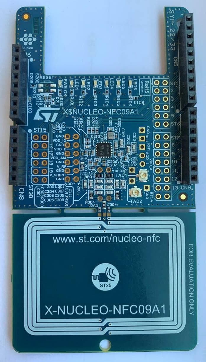
YCPNFC09A1
Oct 01, 2024NFC card reader evaluation board
Equipment Class
DXX - Part 15 Low Power Communication Device Transmitter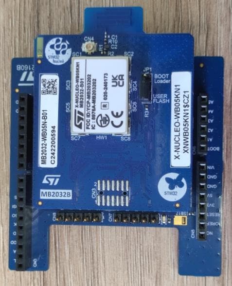
YCP-MB203202
Sep 10, 2024X-NUCLEO-WB05KN1
Equipment Class
DTS - Digital Transmission System
YCP-MB203200
Sep 05, 2024NUCLEO-WB05KZ
Equipment Class
DTS - Digital Transmission System