YCP-MB1389000STM32WL Nucleo-73 evaluation board (NUCLEO-WL55JC1)
STMicroelectronics (Rousset) SAS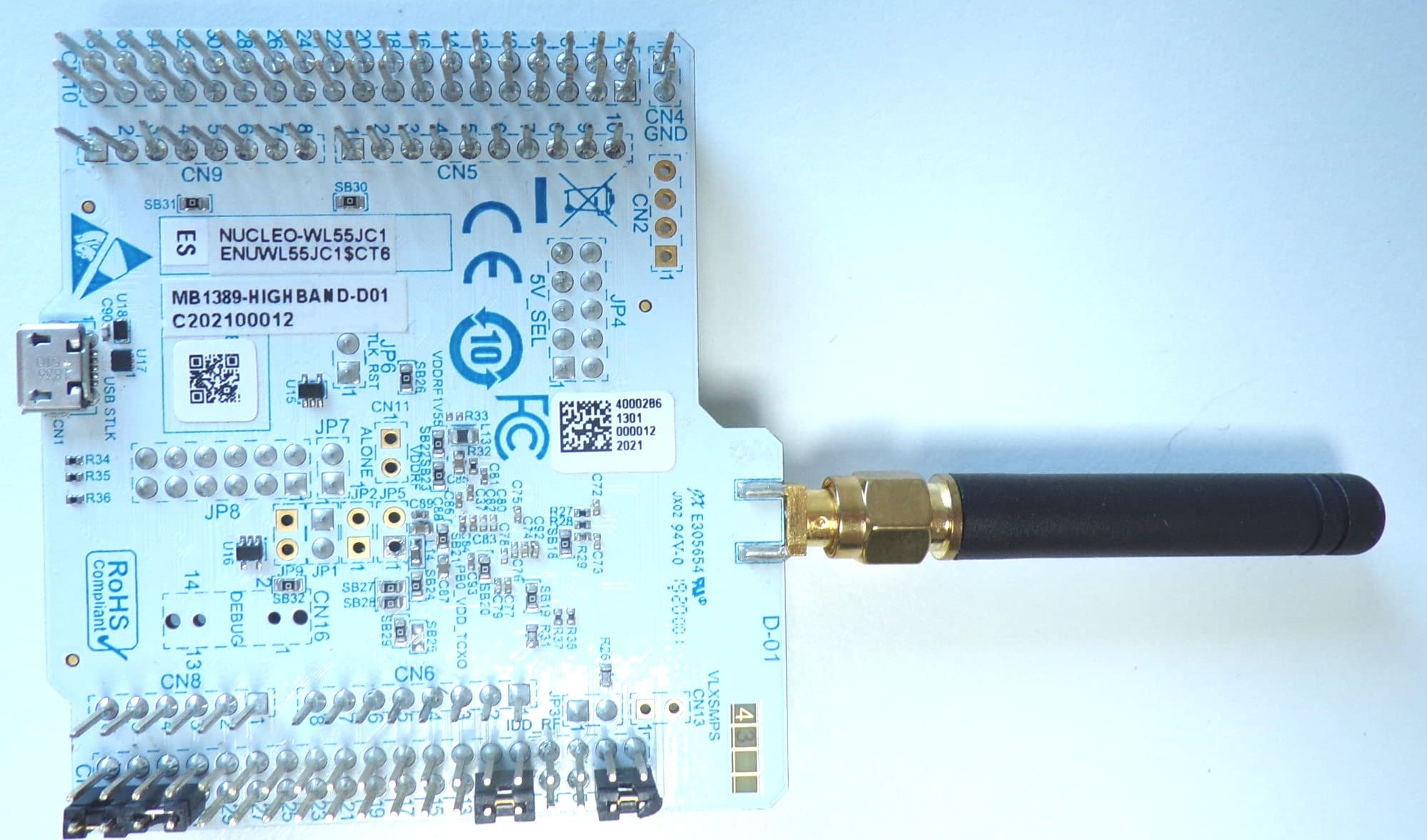
Click to zoom
Application Details
- Equipment Class
- DTS - Digital Transmission System
- Date of Grant
- Jan 27, 2021
- Application Purpose
- Original Equipment
- Date of Application
- Jan 26, 2021
- Equipment Note
- STM32WL Nucleo-73 evaluation board (NUCLEO-WL55JC1)
- Frequency Range
- 925.00000000 - 925.00000000
- Country
- France
Documents & Files
Document Text
Text extracted from the exhibit documents filed with the FCC. Open a document above to read the original.
Users Manual
Introduction The NUCLEO-WL55JC STM32WL Nucleo-64 board, based on the MB1389 reference board (NUCLEO-WL55JC1 and NUCLEO-WL55JC2 order codes), provides an affordable and flexible way for users to try out new concepts and build prototypes with the STM32WL Series microcontroller, choosing from the various combinations of performance, power consumption, and features. The ARDUINO ® Uno V3 connectivity support and the ST morpho headers provide an easy means of expanding the functionality of the STM32WL Nucleo open development platform with a wide choice of specialized shields. The STM32WL Nucleo-64 board does not require any separate probe as it integrates the STLINK-V3E debugger and programmer. The STM32WL Nucleo-64 board is provided with the STM32WL comprehensive software HAL library and various packaged software examples available with the STM32CubeWL MCU Package. Figure 1. NUCLEO-WL55JC top view Figure 2. NUCLEO-WL55JC bottom view Pictures are not contractual. STM32WL Nucleo-64 board (MB1389) UM2592 User manual UM2592 - Rev 1 - November 2020 For further information contact your local STMicroelectronics sales office. www.st.com 1Features • STM32WL55JC microcontroller multiprotocol LPWAN dual-core 32-bit (Arm ® Cortex ® -M4/M0+ at 48 MHz) in UFBGA73 package featuring: – Ultra-low-power MCU – RF transceiver (150 MHz to 960 MHz frequency range) supporting LoRa ® , (G)FSK, (G)MSK, and BPSK modulations – 256-Kbyte Flash memory and 64-Kbyte SRAM • 3 user LEDs • 3 user buttons and 1 reset push-button • 32.768 kHz LSE crystal oscillator • 32 MHz HSE on-board oscillator • Board connectors: – USB with Micro-B – MIPI ® debug connector – ARDUINO ® Uno V3 expansion connector – ST morpho extension pin headers for full access to all STM32WL I/Os • Delivered with SMA antenna • Flexible power-supply options: ST-LINK, USB V BUS , or external sources • On-board STLINK-V3 debugger/programmer with USB re-enumeration capability: mass storage, Virtual COM port, and debug port • Comprehensive free software libraries and examples available with the STM32CubeWL MCU Package • Support of a wide choice of Integrated Development Environments (IDEs) including IAR Embedded Workbench ® , MDK-ARM, and STM32CubeIDE • Suitable for rapid prototyping of end nodes based on LoRaWAN ® , Sigfox ™ , wM-Bus, and many other proprietary protocols • Fully open hardware platform Note:Arm is a registered trademark of Arm Limited (or its subsidiaries) in the US and/or elsewhere. UM2592 Features UM2592 - Rev 1 page 2/49 2Ordering information To order an STM32WL Nucleo-64 board, refer to T able 1. Additional information is available from the datasheet and reference manual of the target STM32. Table 1. List of available products Order code Board reference Target STM32Differentiating feature NUCLEO-WL55JC1 MB1389STM32WL55JCI7U High-frequency band. RF frequency range from 865 to 928 MHz NUCLEO-WL55JC2 Low-frequency band. RF frequency range from 433 to 510 MHz 2.1Codification The meaning of the codification is explained in T able 2. Table 2. Codification explanation NUCLEO-WL55JCXDescriptionExample: NUCLEO-WL55JC1 WLMCU series in STM32 32-bit Arm Cortex MCUs STM32WL Series 55Product line in the Series STM32WL55: Dual-core with LoRa ® , (G)FSK, (G)MSK, and BPSK modulations JSTM32 package pin count73 pins C STM32 Flash memory size: • C for 256 Kbytes 256-Kbyte Flash memory X Frequency band: • 1: high-frequency band • 2: low-frequency band High-frequency band UM2592 Ordering information UM2592 - Rev 1 page 3/49 3Development environment 3.1System requirements • Windows ® OS (7, 8, or 10), Linux ® 64-bit, or macOS ® • USB Type-A or USB Type-C ® to Micro-B cable Note: macOS ® is a trademark of Apple Inc. registered in the U.S. and other countries. All other trademarks are the property of their respective owners. 3.2Development toolchains • IAR Systems - IAR Embedded Workbench ®(1) • Keil ® - MDK-ARM (1) • STMicroelectronics - STM32CubeIDE 1. On Windows ® only. 3.3Demonstration software The demonstration software, included in the STM32Cube MCU Package corresponding to the on-board microcontroller, is preloaded in the STM32 Flash memory for easy demonstration of the device peripherals in standalone mode. The latest versions of the demonstration source code and associated documentation can be downloaded from www.st.com. UM2592 Development environment UM2592 - Rev 1 page 4/49 4Conventions Table 3 provides the conventions used for the ON and OFF settings in the present document. T able 3. ON/OFF convention ConventionDefinition Jumper JPx ONJumper fitted Jumper JPx OFFJumper not fitted Jumper JPx [1-2]Jumper fitted between Pin 1 and Pin 2 Solder bridge SBx ONSBx connections closed by 0 Ω resistor Solder bridge SBx OFFSBx connections left open Resistor Rx ONResistor soldered Resistor Rx OFFResistor not soldered UM2592 Conventions UM2592 - Rev 1 page 5/49 5Quick start The STM32WL Nucleo-64 board is an easy-to-use and low-cost development kit used to evaluate and start development quickly with an STM32WL Series microcontroller in the UFBGA73 package. Before installing and using the product, accept the Evaluation Product License Agreement from the www.st.com/epla webpage. For more information on the STM32WL Nucleo-64 and demonstration software, visit the www.st.com/stm32nucleo webpage. 5.1Getting started Follow the sequence below to configure the STM32WL Nucleo-64 board and launch the demonstration application (refer to Figure 4 for component location): 1. Check jumper positions on board, JP1 (I_SoC) ON, JP3 (BOOT0) ON, JP4 (Power source) on 5V_USB_STLK, JP7 (5V_PWR) ON, and JP8 all 6 jumpers ON The jumper position on the board is explained in Table 4 2. Connect the STM32WL Nucleo-64 board to a PC with a standard USB cable through the CN1 USB connector to power the board. Then the LED5 (PWR) green LED and the LED6 (COM) LED light up, the three LED1, LED2, and LED3 LEDs blink. 3. On the PC, connect a UART terminal to the board using the following settings: – UART…
Text truncated - open the document above for the full version.
Cover Letter(s)
Request for Confidentiality Date: July 28, 2020 Subject: Confidentiality Request for FCC ID: YCP-MB1389000 IC: 8976A-MB1389000 Pursuant to FCC 47 CFR 0.457(d) and 0.459 and IC RSP-100, Section 12.4, the applicant requests that a part of the subject FCC application be held confidential. Type of Confidentiality Requested Exhibit Short Term Permanent Block Diagrams Short Term External Photos Short Term Permanent* 1 Internal Photos Short Term Permanent Operation Description/Theory of Operation Short Term Permanent Parts List & Placement/BOM Short Term Permanent Tune-Up Procedure Short Term Permanent Schematics Short Term Test Setup Photos Short Term Permanent* 3 User’s Manual ST has spent substantial effort in developing this product and it is one of the first of its kind in industry. Having the subject information easily available to "competition" would negate the advantage they have achieved by developing this product. Not protecting the details of the design will result in financial hardship. Permanent Confidentiality: The applicant requests the exhibits listed above as permanently confidential be permanently withheld from public review due to materials that contain trade secrets and proprietary information not customarily released to the public. Short-Term Confidentiality: The applicant requests the exhibits selected above as short term confidential be withheld from public view for a period of ______ days from the date of the Grant of Equipment Authorization and prior to marketing. This is to avoid premature release of sensitive information prior to marketing or release of the product to the public. Applicant is also aware that they are responsible to notify ACB in the event information regarding the product or the product is made available to the public before the requested period has expired. ACB will then release the documents listed above for public disclosure pursuant to FCC Public Notice DA 04-1705. NOTE for Industry Canada Applications: IC currently only distinguishes Permanent Confidentiality exhibits as shown above. Short Term confidentiality is not considered applicable to IC applications. Sincerely, By: __________________________ __________ Joel Huloux______________ (Signature/Title 3 ) (Print name) Director Lobbying and Standardization On behalf of: STMicroelectronics SAS 190 Avenue Celestin Coq 13106 ROUSSET – France FRN: 0019756717 1 - The asterisked items (*) require further information to be provided to ACB before permanent confidentiality will be extended to these exhibits. Please refer to FCC KDB 726920 and the specific Document link for D01 found at: https://apps.fcc.gov/oetcf/kdb/forms/FTSSearchResultPage.cfm?switch=P&id=41731 and review section II, 3) regarding specific information that must accompany these requests. 2 - Please refer to http://acbcert.com/documents/misc-docs/Memo-Short-Term-Vs-Standard-Confidentiality.pdf for complete details.
External Photos
FCC ID: YCP-MB1389000 IC: 8976A-MB1389000 Page 1/1 EXTERNAL PHOTOS OF TESTED EUT
ID Label/Location Info
FCC ID: YCP-MB1389000 IC: 8976A-MB1389000 Page 1/1 PRODUCT LABELING Packaging marking
Internal Photos
FCC ID: YCP-MB1389000 IC: 8976A-MB1389000 INTERNAL PHOTOS OF TESTED EUT Shield removed FCC ID: YCP-MB1389000 IC: 8976A-MB1389000
RF Exposure Info
COORDONNEES SMEE TEL : 04 76 65 76 50 Rue de Taille – ZI Des Blanchisseries FAX : 04 76 66 18 30 38500 VOIRON - France SAS au capital de 50 000 € / RC Grenoble B534 796 453 / SIRET 534 796 453 00015 / code APE 7490B / n° TVA : FR 59 534 796 453 Apparatus: NUCLEO-WL55JC1 RF Exposure Considerations for FCC ID: YCP-MB1389000 The calculation of the MPE is as following: Prediction of MPE limit at a prediction distance: S= ²..4 . R GP ∏ = ²..4 ... R PRIE ∏ S: Power density (mW/cm²) P: Peak output power at antenna terminal (mW) G: Numerical Antenna gain (GidB = 2.0dBi) R: Distance of radiation to antenna (cm) MPE F = 902.5 / 925.0MHz E.I.R.P = 199.5mW (21dBm + 2.0dBi) R= 20cm S=0.04mW/cm² MPE limit for uncontrolled exposure: 0.6mW/cm² Below MPE limit Note: RF output power is taken as rated power including tune-up tolerances. Conclusion: Therefore the device complies with FCC’s RF radiation exposure limits for general population for a mobile device. Certified By Laurent CHAPUS (Agent for this device) SMEE Rue de Taille ZI des Blanchisseries 38500 Voiron - France [email protected] FCC Registration Number: 0020356952 (FRN) Applicant for this device: STMicroelectronics SAS 190 Avenue Celestin Coq 13106 ROUSSET – France Mr. Joel Huloux Director Lobbying and Standardization FRN: 0019756717
Test Report
Rapport d’essais / Test Report N° : 13295-FCC-IC-2 Page 1 / 30 COORDONNEES SMEE TEL : 04 76 65 76 50 Rue de Taille – ZI Des Blanchisseries FAX : 04 76 66 18 30 38500 VOIRON - France SAS au capital de 50 000 € / RC Grenoble B534 796 453 / SIRET 534 796 453 00015 / code APE 7490B / n° TVA : FR 59 534 796 453 FCC Test Firm Designation Number: FR0014 ISED Wireless Device Testing Laboratory CAB Number: FR0004 Matériel testé : Equipment under test: ST / NUCLEO–WL55JC1 (Trademark / Marketing name or product reference) Demandeur: Applicant : ST Microelectronics Rousset SAS 190, rue Célestin Coq 13106 ROUSSET Cedex – France Client : Customer: ST Microelectronics M. Patrice Derouet 9-11 rue Pierre Félix Delarue 72100 Le Mans – France Numéro d’affaire : Work number : 13295 Référence de la proposition : Proposal number: 012020-23903 Date de l’essai : Date of test: Du 22 au 24 juillet 2020 July 22 nd to 24 th , 2020 Objectif des essais : Test purpose: EMC qualification accordingly to following standards: - CFR 47, FCC Part 15, Subpart C (Chapter 15.247 - Operation within the bands 902–928 MHz, 2400–2483.5 MHz, and 5725–5850 MHz) - Industry Canada RSS-247, Issue 2 (Digital Transmission Systems Operating in the Bands 902–928 MHz) Measurement standards: ANSI C63.10 (2013) Lieu du test: Test location: SMEE, Rue de Taille 38500 VOIRON - France Test réalisé par : Test realized by: Laurent CHAPUS Conclusion : Conclusion: L’équipement satisfait aux prescriptions et essais des normes citées en référence. The appliance complies with requirements and tests of above mentioned standards. Ed. Date Modifications / Pages Written by : Visa Approved by: Visa 1 2 November 12 th , 2020 December 8, 2020 Initial Edition TCB review Laurent CHAPUS Technical Manager Regis ANCEL General Manager La copie de ce document n'est permise que sous sa forme intégrale. Ce document est le résultat d’essais effectués sur un échantillon. Il ne préjuge pas de la conformité de l’ensemble des produits fabriqués à l’objet essayé. This document shall not be reproduced, except in full. This document contains results related only to the item tested. It does not imply the conformity of the whole production to the item tested. Accréditation N° 1-6356 Portée disponible sur : Scope available on : www.cofrac.fr Page 2 / 30 Rapport d’essai / Test Report N° : 13295-FCC-IC-2 Contents 1. NORMATIVES REFERENCES ......................................................................................................... 3 2. TEST SYNTHESIS ............................................................................................................................ 4 3. EQUIPMENT UNDER TEST (EUT) ................................................................................................... 5 4. TEST CONDITIONS.......................................................................................................................... 5 5. MODIFICATIONS OF THE EUT ........................................................................................................ 5 6. SPECIAL ACCESSORY .................................................................................................................... 5 7. MEASUREMENT UNCERTAINTY .................................................................................................... 6 8. FIELD STRENGTH CALCULATION .................................................................................................. 6 9. CONDUCTED EMISSION MEASUREMENT (150KHZ-30MHZ) ........................................................ 7 10. 6DB BANDWIDTH ....................................................................................................................... 10 11. FUNDAMENTAL EMISSION OUTPUT POWER .......................................................................... 11 12. MAXIMUM POWER SPECTRAL DENSITY LEVEL IN THE FUNDAMENTAL EMISSION ........... 13 13. UNWANTED SPURIOUS EMISSIONS (CONDUCTED EMISSIONS) ......................................... 15 14. UNWANTED EMISSIONS IN NON-RESTRICTED FREQUENCY BANDS (RADIATED EMISSIONS) .......................................................................................................................................... 18 15. UNWANTED EMISSIONS IN RESTRICTED FREQUENCY BANDS ........................................... 21 16. OCCUPIED BANDWIDTH (99%) ................................................................................................. 29 Page 3 / 30 Rapport d’essai / Test Report N° : 13295-FCC-IC-2 1. Normatives References FCC qualification according to: Standards Applied Title ANSI C63.10 (2013) X American National Standard for Testing Unlicensed Wireless Devices CFR47, Part 15 X Telecommunication – Federal Communication Commission – Radio frequency devices, Sections 15.109 / 15.209 / 15.247 ISED qualification according to: Standards Applied Title RSS-Gen (Issue 5/2019) X General Requirements and Information for the Certification of Radio Apparatus RSS-247 (Issue2/2017) X Digital Transmission Systems (DTSs), Frequency Hopping Systems (FHSs) and Licence-Exempt Local Area Network (LE-LAN) Devices Note: Following guidance are used - DTS Measurement Guidance 558074 D01 v05r02 - Determining ERP and EIRP Guidance 412172 D01 v01r01 Deviation from standard: None Page 4 / 30 Rapport d’essai / Test Report N° : 13295-FCC-IC-2 2. Test synthesis TEST Paragraph number FCC Part 15 / ISED ICES & RSS Spec. FCC Part 15 / ISED ICES & RSS RESULTS (comments) Conducted emissions test 15.207 (a) RSS-Gen § 8.8 Table 15.207 (a) Table 4 / RSS-Gen PASS 6dB Bandwidth 15.247 (a) (2) RSS-247 § 5.2 (a) At least 500kHz PASS Maximum Peak Output Power 15.247 (b) (3) & (4) RSS-247 § 5.4 (d) 1W max / 30dBm (Conducted) 4W max / 36dBm (EIRP) PASS Maximum Power Spectral Density 15.247 (e) RSS-247 § 5.2 (b) 8dBm in a 3kHz band segment PASS Unwanted emissions into Non Restricted Frequency Bands 15.247 (d) / RSS-247 § 5.5 -30dBc in any 100kHz outside frequency band. PASS Unwanted emissions into Restr…
Text truncated - open the document above for the full version.
Test Setup Photos
FCC ID: YCP-MB1389000 IC: 8976A-MB1389000 Page 1/2 MEASUREMENT PHOTO Conducted emissions an AC mains Radiated emissions Test setup for frequency below 1GHz FCC ID: YCP-MB1389000 IC: 8976A-MB1389000 Page 2/2 Test setup for frequency above 1GHz Conducted RF measurement
Contact Information
Applicant
PASCAL SCAFIDI(MDG Group VP Quality & Reliability)
Technical Contact
STMicroelectronics (Grand Ouest) SASPatrice Derouet
[email protected]01133613493375
9 et 11, rue Pierre Felix Delarue · LE MANS · France
Test Firm
SMEELaurent Chapus
[email protected]+33 4 76 65 76 50
Technical Specifications
| # | Rule Parts | Frequency Range | Power Output |
|---|---|---|---|
| 1 | 15C | 925 MHz - 925 MHz | 100.00 mW |
Other Applications from STMicroelectronics (Rousset) SAS
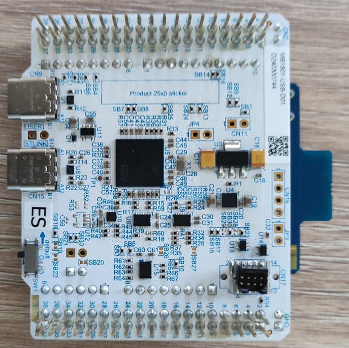
YCP-MB229300
Jun 08, 2026BLE RF evaluation board
Equipment Class
DTS - Digital Transmission System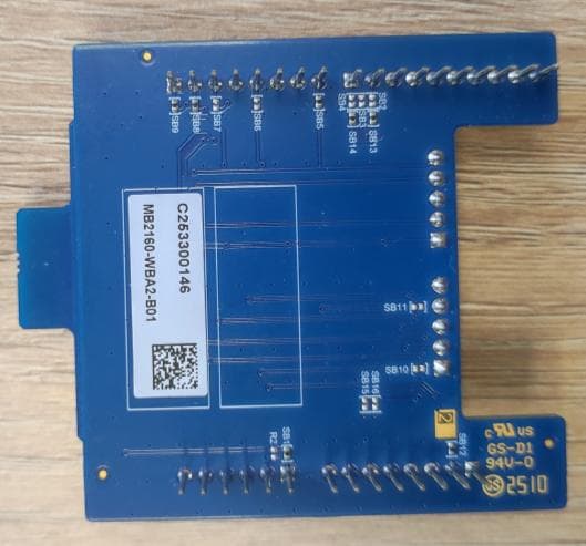
YCP-MB229301
Jun 08, 2026BLE RF evaluation board
Equipment Class
DTS - Digital Transmission System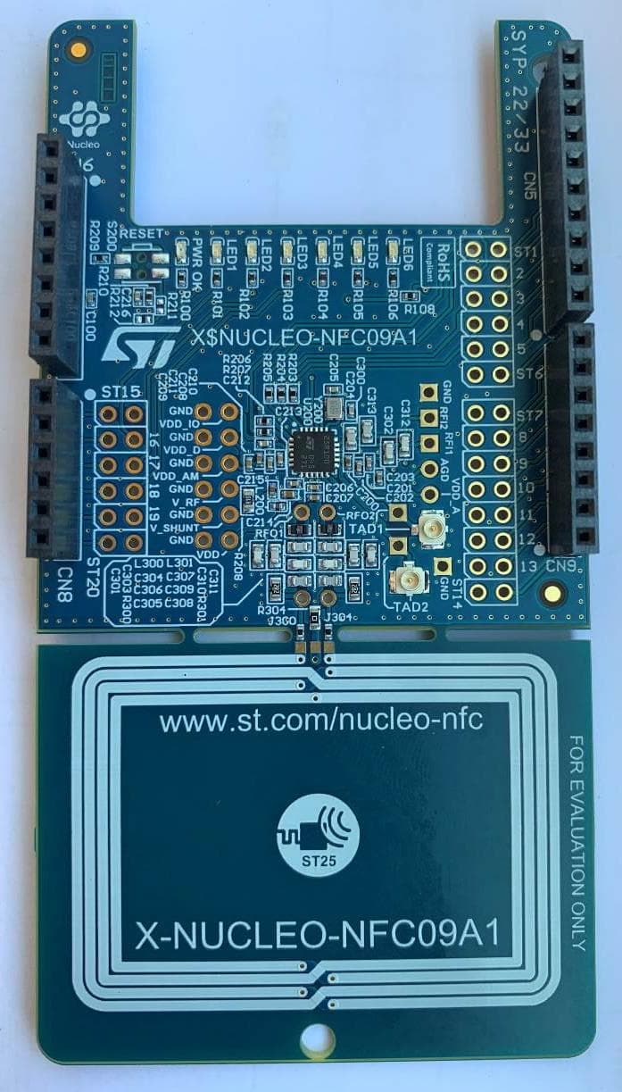
YCPNFC09A1
Oct 01, 2024NFC card reader evaluation board
Equipment Class
DXX - Part 15 Low Power Communication Device Transmitter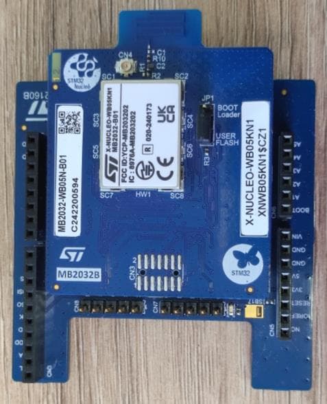
YCP-MB203202
Sep 10, 2024X-NUCLEO-WB05KN1
Equipment Class
DTS - Digital Transmission System
YCP-MB203200
Sep 05, 2024NUCLEO-WB05KZ
Equipment Class
DTS - Digital Transmission System