YCPDEMOCR95HFRFID Reader
STMicroelectronics (Rousset) SAS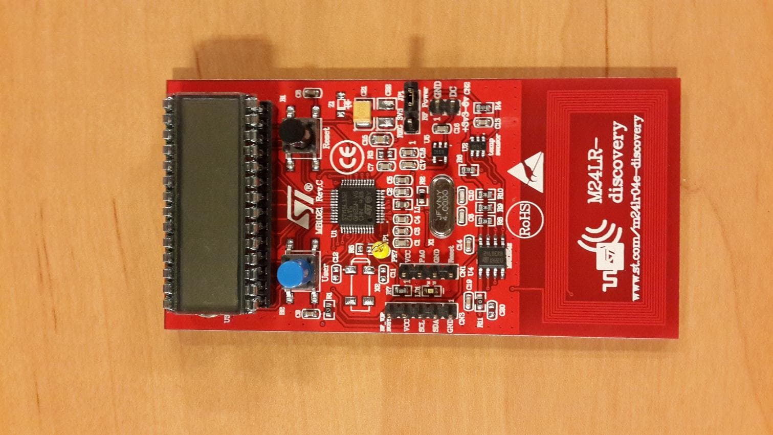
Click to zoom
Application Details
- Equipment Class
- DXX - Part 15 Low Power Communication Device Transmitter
- Date of Grant
- Feb 22, 2015
- Application Purpose
- Original Equipment
- Date of Application
- Feb 22, 2015
- Equipment Note
- RFID Reader
- Frequency Range
- 13.56000000 - 13.56000000
- Country
- France
Documents & Files
Document Text
Text extracted from the exhibit documents filed with the FCC. Open a document above to read the original.
Users Manual
13 February 2015DocID023883 Rev 31/19 UM1589 User manual M24LR-DISCOVERY kit user guide Introduction The M24LR-DISCOVERY kit helps you evaluate the M24LRXX-E Dual Interface EEPROM that features an energy harvesting analog output, as well as a user-configurable digital output. The M24LR-DISCOVERY kit is delivered with a battery-less M24LR board that can be powered by RFID readers or NFC phones supporting the ISO/IEC15693 protocol. It is based on an M24LR04E-R I²C - ISO/IEC15693 Dual Interface EEPROM, an 8-bit STM8L152C6T6 ultralow power microcontroller, and includes an STTS751 temperature sensor, a 24-segment LCD, and 2 push buttons. The M24LR-DISCOVERY kit also comes with an USB RF transceiver demonstration board that includes the CR95HF 13.56-MHz multi-protocol contactless transceiver. It is based on a 32-bit, STM32F103CBT6 performance line microcontroller and is connected to a computer host via its USB connector. Figure 1. M24LR evaluation board Figure 2. RF transceiver demonstration board Table 1. Applicable tools TypeApplicable tool Evaluation toolsM24LR-DISCOVERY www.st.com ContentsUM1589 2/19DocID023883 Rev 3 Contents 1Quick start . . . . . . . . . . . . . . . . . . . . . . . . . . . . . . . . . . . . . . . . . . . . . . . . . 5 1.1Getting started with the M24LR04E Dual Interface EEPROM . . . . . . . . . . 5 1.2Using the M24LR board with Android NFC phones . . . . . . . . . . . . . . . . . . 6 1.3System requirements . . . . . . . . . . . . . . . . . . . . . . . . . . . . . . . . . . . . . . . . . 6 1.4Development toolchain . . . . . . . . . . . . . . . . . . . . . . . . . . . . . . . . . . . . . . . . 6 2Features . . . . . . . . . . . . . . . . . . . . . . . . . . . . . . . . . . . . . . . . . . . . . . . . . . . 7 3Hardware and layout description . . . . . . . . . . . . . . . . . . . . . . . . . . . . . . . 8 3.1M24LR board description . . . . . . . . . . . . . . . . . . . . . . . . . . . . . . . . . . . . . . 8 3.2M24LR board power selection . . . . . . . . . . . . . . . . . . . . . . . . . . . . . . . . . . 9 3.3RF transceiver board description . . . . . . . . . . . . . . . . . . . . . . . . . . . . . . . .11 3.4RF transceiver demonstration board powering and startup . . . . . . . . . . . .11 3.5Program/debug the M24LR board . . . . . . . . . . . . . . . . . . . . . . . . . . . . . . 12 3.6Program/debug the RF transceiver demo board . . . . . . . . . . . . . . . . . . . 12 4Federal Communications Commission (FCC) and Industry Canada (IC) Compliance Statements 13 4.1FCC Compliance Statement . . . . . . . . . . . . . . . . . . . . . . . . . . . . . . . . . . . 13 4.1.1Part 15.19 . . . . . . . . . . . . . . . . . . . . . . . . . . . . . . . . . . . . . . . . . . . . . . . 13 4.1.2Part 15.105 . . . . . . . . . . . . . . . . . . . . . . . . . . . . . . . . . . . . . . . . . . . . . . 13 4.1.3Part 15.21 . . . . . . . . . . . . . . . . . . . . . . . . . . . . . . . . . . . . . . . . . . . . . . . 13 4.2IC Compliance Statement . . . . . . . . . . . . . . . . . . . . . . . . . . . . . . . . . . . . . 13 4.3IC Déclaration de conformité . . . . . . . . . . . . . . . . . . . . . . . . . . . . . . . . . . 13 5Electrical schematic diagrams . . . . . . . . . . . . . . . . . . . . . . . . . . . . . . . . 15 6Revision history . . . . . . . . . . . . . . . . . . . . . . . . . . . . . . . . . . . . . . . . . . . 18 DocID023883 Rev 33/19 UM1589List of tables 3 List of tables Table 1.Applicable tools. . . . . . . . . . . . . . . . . . . . . . . . . . . . . . . . . . . . . . . . . . . . . . . . . . . . . . . . . . . 1 Table 2.Available user modes . . . . . . . . . . . . . . . . . . . . . . . . . . . . . . . . . . . . . . . . . . . . . . . . . . . . . . 5 Table 3.M24LR board programming and debug connector . . . . . . . . . . . . . . . . . . . . . . . . . . . . . . . 12 Table 4.Document revision history . . . . . . . . . . . . . . . . . . . . . . . . . . . . . . . . . . . . . . . . . . . . . . . . . 18 List of figuresUM1589 4/19DocID023883 Rev 3 List of figures Figure 1.M24LR evaluation board. . . . . . . . . . . . . . . . . . . . . . . . . . . . . . . . . . . . . . . . . . . . . . . . . . . . 1 Figure 2.RF transceiver demonstration board . . . . . . . . . . . . . . . . . . . . . . . . . . . . . . . . . . . . . . . . . . 1 Figure 3.M24LR board layout . . . . . . . . . . . . . . . . . . . . . . . . . . . . . . . . . . . . . . . . . . . . . . . . . . . . . . . 8 Figure 4.Jumper JP1 set in RF power position . . . . . . . . . . . . . . . . . . . . . . . . . . . . . . . . . . . . . . . . . . 9 Figure 5.Jumper JP1 in “REG_3V3” position and external power connection . . . . . . . . . . . . . . . . . . 9 Figure 6.External antenna connection with voltage regulator bypass. . . . . . . . . . . . . . . . . . . . . . . . 10 Figure 7.External antenna connection using M24LR board voltage regulator . . . . . . . . . . . . . . . . . 10 Figure 8.RF transceiver board layout (top and bottom) . . . . . . . . . . . . . . . . . . . . . . . . . . . . . . . . . . 11 Figure 9.M24LR board schematics . . . . . . . . . . . . . . . . . . . . . . . . . . . . . . . . . . . . . . . . . . . . . . . . . . 15 Figure 10.RF transceiver demonstration board schematics (STM32 connections) . . . . . . . . . . . . . . 16 Figure 11.RF transceiver demonstration board schematics (CR95HF connections) . . . . . . . . . . . . . 17 DocID023883 Rev 35/19 UM1589Quick start 1 Quick start The M24LR-DISCOVERY kit is a low-cost and ready-to-use development kit used to evaluate the functions and performance of the M24LR Dual Interface EEPROM family and its energy harvesting capability. For more information on the M24LR-DISCOVERY kit and associated demonstration software, please visit www.st.com/m24lr04e-discovery. 1.1 Getting started with the M24LR04E Dual Interface EEPROM 1.On the M24LR board, ensure that a jumper is placed on connector JP1 in the RF power position (jumper on the right side as shown in Figure 4). 2. Download and install the M24LR/CR95 appl…
Text truncated - open the document above for the full version.
Block Diagram
CR95HFSTM32F103RUSB Connector JTAG Connector Antenna loop 13.56MHz Antenna tuning circuit 27.12 MHz 8MHz M24LR STM8L152 Temperature Sensor Antenna loop 13.56MHz Antenna 4MHz 24 Segment LCD I2C Bus
Cover Letter(s)
DECLARATION OF CONFORMITY Per: 47 CFR Part 15 - Radio Frequency Devices Responsible Party: STMICROELECTRONICS, INC. 750 Canyon Drive, Suite 300 Coppell, Texas 75019 United States of America 972-466-6000 The following device: Product name: M24LR-Discovery Part number: MB1054-B & MB1021-C Was tested by: Test facility: EMITECH ANGERS laboratory at JUIGNE SUR LOIRE (49) FRANCE FCC 2.948 Listed Site Registration Number: 90469 FCC Accredited under US-EU MRA Designation Number: FR0009 Test Firm Registration Number: 873677 And found to comply with part 15 of the FCC Rules. Operation is subject to the following two conditions: (1) This device may not cause harmful interference, and (2) this device must accept any interference received, including interference that may cause undesired operation. As sold by the Responsible Party, each device unit marketed under this Declaration of Conformity is identical to the unit tested and found acceptable with the standards, and the records maintained by the Responsible Party continue to reflect the device being produced under the Declaration of Conformity within the variation that can be expected due to quantity production and testing on a statistical basis. This certificate is issued by: STMICROELECTRONICS, INC. By: Name: Brian Mielewski Title: VP of Quality – Region Date: February 10, 2015
ID Label/Location Info
Final Product: Board Dynamic Tag Board NFC reader FCC Marking:
ID Label/Location Info
FCC ID: FCC Logo As there is not enough place on board, following information are in User manual: This device complies with Part 15 of the FCC Rules. Operation is subject to the following two conditions: (1) this device may not cause harmful interference, and (2) this device must accept any interference received, including interference that may cause undesired operation.
Operational Description
For further information contact your local STMicroelectronics sales office. March 2013DocID023090 Rev 21/4 4 M24LR-DISCOVERY M24LR-DISCOVERY evaluation kit Data brief Features •M24LR board – M24LR04E-RMN6T/2 Dual Interface EEPROM with I 2 C and ISO/IEC 15693 RF interfaces, 4 Kbits of EEPROM and password protection in SO8N package – STM8L152C6T6 8-bit microcontroller, with 8 Kbytes of Flash memory – STTS751-0WB3F, low-voltage digital temperature sensor – 20 x 40 mm inductive antenna etched on the PCB – Two function buttons (User and Reset) – SWIM connector for programming and debugging –I 2 C connectors – LCD (24 segments, 4 commons) •RF transceiver board – CR95HF-VMD5T 13.56 MHz multi-protocol contactless transceiver IC with SPI and UART serial access – STM32F103CB 32-bit microcontroller, with 128 Kbytes of Flash memory – 47 x 34 mm 13.56 MHz inductive antenna etched on PCB and associated circuitry – USB connector for communication with host PC and demonstration board powering Figure 1. M24LR board and RF transceiver board RF transceiver board M24LR board www.st.com DescriptionM24LR-DISCOVERY 2/4DocID023090 Rev 2 1 Description M24LR-DISCOVERY is a ready-to-use kit which features the M24LR04E-R Dual Interface EEPROM IC. It addresses a wide range of applications such as industrial or medical equipment and consumer electronics. This kit contains 2 different boards (see Figure 1): •The M24LR board is battery-less and is powered by RFID readers or NFC-enabled phones supporting ISO/IEC 15693. •The RF transceiver board is an RFID reader demonstration board and is composed, among other parts, of a CR95HF (13.56 MHz multi-protocol contactless transceiver IC with SPI and UART serial access). This board has to be plugged in to a PC and comes with a demonstration software. The M24LR board also works with Android NFC phones supporting ISO/IEC 15693. An application called NfcV-Reader is available on Google Play. Performance may vary depending on NFC phone's RF management. System requirements •Windows PC (2000, XP, Vista, 7) •ISO/IEC 15693 capable NFC phones 1.1 Demonstration software The M24LRxx application software can be uploaded from www.st.com/m24lr04e-discovery and installed on your PC. It consists in: •an M24LR/CR95 application software setup file [STSW-M24LR011] •an STM8L firmware 1.1.1 M24LRxx application software The PC software allows to: 1.Launch setup.exe executable. 2. Choose CR95HF DEMO KIT tab. 3. Select demo NDEF messages tab. 4. Click on demo NDEF & Energy Harvesting tab. The latest versions of this demonstration source code and associated documentation can be downloaded from www.st.com/m24lr04e-discovery. 1.1.2 STM8L firmware Development toolchain In case of an STM8L firmware change, the user has to download: •STMicroelectronics, ST Visual Develop (STVD) DocID023090 Rev 23/4 M24LR-DISCOVERYRevision history STM8L firmware Demonstration software is preloaded in the board's Flash memory. This demonstration displays on the LCD: •The text messages stored in the M24LR04E-R Dual Interface EEPROM •The internal voltage of the M24LR board •The ambient temperature measured from the sensor 1.2 Android application Install the NfcV-Reader applet available from Google Play. This application enables the NFC communication (Settings-Wireless & Networks-NFC) for evaluation on an Android device. 1.Download the NfcV-Reader App from Google Play and install it on the Android device. 2. Launch the NfcV-Reader application. 3. Place the device's NFC antenna close to the M24LR board antenna. The NFC phone powers the M24LR board. The text message can be changed using the NFC phone (select NDEF function and select write NDEF message menu). Performance may vary depending on NFC phone's RF management. 2 Revision history Table 1. Document revision history DateRevisionChanges 17-Jul-20121Initial release. 11-Mar-20132 Updated the first item of the M24LRxx application software in Section 1.1: Demonstration software. Updated the name of the executable file in Section 1.1.1: M24LRxx application software. M24LR-DISCOVERY 4/4DocID023090 Rev 2 Please Read Carefully: Information in this document is provided solely in connection with ST products. STMicroelectronics NV and its subsidiaries (“ST”) reserve the right to make changes, corrections, modifications or improvements, to this document, and the products and services described herein at any time, without notice. All ST products are sold pursuant to ST’s terms and conditions of sale. Purchasers are solely responsible for the choice, selection and use of the ST products and services described herein, and ST assumes no liability whatsoever relating to the choice, selection or use of the ST products and services described herein. No license, express or implied, by estoppel or otherwise, to any intellectual property rights is granted under this document. If any part of this document refers to any third party products or services it shall not be deemed a license grant by ST for the use of such third party products or services, or any intellectual property contained therein or considered as a warranty covering the use in any manner whatsoever of such third party products or services or any intellectual property contained therein. UNLESS OTHERWISE SET FORTH IN ST’S TERMS AND CONDITIONS OF SALE ST DISCLAIMS ANY EXPRESS OR IMPLIED WARRANTY WITH RESPECT TO THE USE AND/OR SALE OF ST PRODUCTS INCLUDING WITHOUT LIMITATION IMPLIED WARRANTIES OF MERCHANTABILITY, FITNESS FOR A PARTICULAR PURPOSE (AND THEIR EQUIVALENTS UNDER THE LAWS OF ANY JURISDICTION), OR INFRINGEMENT OF ANY PATENT, COPYRIGHT OR OTHER INTELLECTUAL PROPERTY RIGHT. ST PRODUCTS ARE NOT AUTHORIZED FOR USE IN WEAPONS. NOR ARE ST PRODUCTS DESIGNED OR AUTHORIZED FOR USE IN: (A) SAFETY CRITICAL APPLICATIONS SUCH AS LIFE SUPPORTING, ACTIVE IMPLANTED DEVICES OR SYSTEMS WITH PRODUCT FUNCTIONAL SAFETY REQUIREMENTS; (B) AERONAUTIC APPLICATIONS; (C) AUTOMOTIVE APPLICATIONS OR ENVIRONMENTS, AND/OR (D) AEROSPACE APPLICATIONS OR ENVIRON…
Text truncated - open the document above for the full version.
Parts List/Tune Up Info
Bill of Materials Source Data From:M24LR04E-Discovery.PrjPCB Project:M24LR04E-Discovery.PrjPCB Variant:None Creation Date:15/03/2012 Print Date:05-Mar-13 NOTE: the PCB board color must be RED CommentDesignatorFootprintQuantityAssemblyOrdered byComments TD0341X-G01-BLAB1PB10 1 blackSubcontractor TD0341X-G01-BLUB2PB10 1 blueSubcontractor 1uFC10603C 1 Subcontractor 1uFC20603C 1 Subcontractor 100nFC30603C 1 Subcontractor 100nFC40603C 1 Subcontractor 100nFC50603C 1 Subcontractor 20pFC60603C 1 Subcontractor CC0603KRX5R8BB105C70603C 1 Subcontractor 100nFC80603C 1 Subcontractor 100nFC90603C 1 Subcontractor 20pFC100603C 1 Subcontractor 6.8pFC110603C 1 Not fittedSubcontractor 6.8pFC120603C 1 Not fittedSubcontractor 100nFC130603C 1 Subcontractor 10nFC140603C 1 Subcontractor 4.7uFC150805C 1 Subcontractor 1uF[ceramic]C160603C 1 Subcontractor 1uF[ceramic]C170603C 1 Subcontractor 100nFC180603C 1 Subcontractor 10nFC190603C 1 Subcontractor [N/A]C200603C 1 Subcontractor TLNK157M006R2500 C211206C 1 Subcontractor TLNK157M006R2500 C221206C 1 Not fittedSubcontractor Header 4CN1Header 4 1 Subcontractor Header 2CN2HDR1X2 1 Subcontractor Header 5CN3Header 5 1 Subcontractor JP1SIP3 1 2<->3SubcontractorRF power before delivery FCM1608KF-601T03L10603L 1 Subcontractor 19-217/BHC-ZL1M2RY/3TLD1LED0603 1 Subcontractor 4K7R10603R 1 Subcontractor 60R20603R 1 Subcontractor 0R30603R 1 Not fittedSubcontractor 33KR40603R 1 Subcontractor 0R50603R 1 Not fittedSubcontractor 20KR60603R 1 Subcontractor 660R70603R 1 Subcontractor 20KR80603R 1 Subcontractor 15KR90603R 1 Subcontractor 15KR100603R 1 Subcontractor 0R110603R 1 Subcontractor PE7TP1TP 1 Subcontractor STM8L152C6T6U1LQFP48 1 STM STTS751-0WB3FU2SOT23-6L 1 STM GH08172TU3DIP28 1 Subcontractor M24LR04E-RMN6T/2U4SO8 1 STM LD3985M33RU5SOT23-5L 1 STM HC-49S-C20SSA-4.000X1XTAL1 1 Subcontractor 4MHz crystal MC306-G-06Q-32.768 (manufacturer JFVNY)X2SM8 1 Not fittedSubcontractor MMSZ5227BT1Z1SOD123 1 Not fittedSubcontractor 11328615200 1 SubcontractorLCD socket ApprovedNotes Altium Limited Confidential 05-03-13Page 1
Parts List/Tune Up Info
DesignerRelease VerifierVerification QtyManufacturerInstall.Sim. C o 1ANTELECTHYES 1LyconnTHYES 1AVXSMDYES 5AVXSMDYES 5YAGEOSMDYES 3AVXSMDYES 3YAGEOSMDYES 1SPRAGUESMDYES 1AVXSMDYES 1SPRAGUESMDYES 1SPRAGUESMDYES 2MURATASMDYES 2YAGEO SMDYES 2MURATASMDYES 2YAGEO SMDYES TAJA105K016R988 988 . Package : 0603, Tolerance : 5%, Capacity : 10pF, Voltage : 50V, Min temp. : -55°C, Max temp. : 125°C Installed positions (2) : C7-C8Not installed positions (0) : CAP0003361 988 . replacement GRM39 CERAMIC SMD CAP (COG)GRM1885C1H100KA01D .988GRM39 CERAMIC SMD CAP (X7R)GRM1887R1H103KA01D 10nF,0603,50V,10%,X7R,YAGEOCC0603KRX7R9BB103 replacement CAP0003362 988 10pF,5%,50V,NPO,0603,YAGEO 988 CC0603JRNPO9BN100 . Package : 293D-D, Tolerance : 10%, Capacity : 10μF, Voltage : 35V, Min temp. : -55°C, Max temp. : 85°C Installed positions (1) : C18Not installed positions (0) : CAP0002231293D TANTAL SMD POL CAP293D106X9035D988 . Package : 293D-C, Tolerance : 10%, Capacity : 2.2μF, Voltage : 35V, Min temp. : -55°C, Max temp. : 85°C Installed positions (1) : C28Not installed positions (0) : CAP0002227293D TANTAL SMD POL CAP293D225X9035C988 . Package : 293D-A, Tolerance : 10%, Capacity : 1μF, Voltage : 16V, Min temp. : -55°C, Max temp. : 85°C Installed positions (1) : C9Not installed positions (0) : CAP0002223293D TANTAL SMD POL CAP293D105X9016A988 replacement1uF,10%,16V,Tan-A,AVX CAP0000480CERAMIC SMD CAP (X7R)08055C104KAT988 replacement100nF,10%,50V,X7R,0805,YAGEO988 988. Package : TAJ-A, Tolerance : 10%, Capacity : 4.7μF, Voltage : 10V, Min temp. : -55°C, Max temp. : 125°C Installed positions (1) : C17Not installed positions (0) : TAJA TANTAL SMD CAPTAJA475K010R 988. Package : 0603, Tolerance : 10%, Capacity : 100nF, Voltage : 16V, Min temp. : -55°C, Max temp. : 125°C Installed positions (5) : C19-C23Not installed positions (0) : 100nF,10%,16V,X7R,0603,YAGEOCC0603KRX7R7BB104replacement CAP0000055CERAMIC SMD CAP (X7R) BAR00018993PTS V M BAR PITCH 2.54A60-254-03-7G CAP0000053 CC0805KRX7R9BB104 0603YC104KAT Package : 0805, Tolerance : 10%, Capacity : 100nF, Voltage : 50V, Min temp. : -55°C, Max temp. : 125°C Installed positions (3) : C16, C26-C27Not installed positions (0) : 988G CNT N.A. Installed positions (1) : ST1Not installed positions (0) : replacementpin header male,2.54mm,1*03,L=11.6,Vertical313103S111116988 Version PNDescriptionReferenceSupplier NameType Observations Bill of Material ReferenceCR95HF BOM , v., Confidential Page 1 / 6 1MURATASMDYES 1 YAGEO SMDYES 1MURATASMDYES 1 YAGEO SMDYES 2MURATASMDYES 2 YAGEO SMDYES 2AVXSMDYES 2 YAGEO SMDYES 2AVXSMDYES 2 YAGEO SMDYES 2 murata SMDYES 2AVXSMDYES 2 YAGEO SMDYES 2 MURATA SMDYES 2AVXSMDYES 2 YAGEO SMDYES replacement0603(1608) ±1% NP0 50 V 150 GRM1885C1H151FA01D 988 . Package : 0603, Tolerance : 10%, Capacity : 10nF, Voltage : 50V, Min temp. : -55°C, Max temp. : 125°C Installed positions (2) : C10, C25Not installed positions (0) : 988CAP0003371 988 CAP0019325MULTILAYER CERAMIC CAPACITORS 180pF 0603 1% . Package : 0603, Tolerance : 1%, Capacity : 180pF, Voltage : 50V, Min temp. : -55°C, Max temp. : 125°C Installed positions (2) : C01-C02Not installed positions (0) : replacement0603(1608) ±1% NP0 50 V 180 CC0805KRX7R9BB472 988 . . Package : 0603, Tolerance : 1%, Capacity : 150pF, Voltage : 25V, Min temp. : -55°C, Max temp. : 125°C Installed positions (2) : C2A, C2BNot installed positions (0) : 988 replacement replacement0603(1608) ±1% NP0 50 V 150 CC0603FCNPO9BN151 CAP0019324MULTILAYER CERAMIC CAPACITORS 150pF 0603 1%LD033A151FAB2A 100nF,10%,50V,X7R,0603,YAGEO; 988 CAP0019326MULTILAYER CERAMIC CAPACITORS 82pF 0603 1%LD031A820FAB2A988 replacement0603(1608) ±1% NP0 100 V 82CC0603FRNPO0BN820988 988 Package : 0603, Tolerance : 10%, Capacity : 100nF, Voltage : 25V, Min temp. : -55°C, Max temp. : 125°C Installed positions (2) : C15, C29Not installed positions (0) : CC0603FCNPO9BN181 LD035A181FAB2A replacement CC0603KRX7R9BB104 Package : 0805, Tolerance : 5%, Capacity : 20pF, Voltage : 50V, Min temp. : -55°C, Max temp. : 125°C Installed positions (2) : C13-C14Not installed positions (0) : .CAP0012229 988 CERAMIC SMD CAPACITOR (X7R)06033C104KAT2A988 CAP0007672GRM40 CERAMIC SMD CAP (COG)GRM2165C1H200JA01L988 replacement0805(2012) ±5% NP0 50 V 20 988 . Package : 0805, Tolerance : 10%, Capacity : 4.7nF, Voltage : 50V, Min temp. : -55°C, Max temp. : 125°C Installed positions (1) : C24Not installed positions (0) : CAP0003416GRM40 CERAMIC SMD CAP (X7R)GRM216R71H472JA01D988 replacement0805(2012) ±10% X7R 50 V 4,700 Package : 0603, Tolerance : 10%, Capacity : 1nF, Voltage : 50V, Min temp. : -55°C, Max temp. : 125°C Installed positions (1) : C5Not installed positions (0) : 9881nF,10%,50V,X7R,0603,YAGEOCC0603KRX7R9BB102replacement GRM39 CERAMIC SMD CAP (X7R)GRM188R71H102KA01D CC0805JRNPO9BN200 988 GRM1885C1H181FA01D 0603(1608) ±1% NP0 50 V 180 BOM , v., Confidential Page 2 / 6 2 MURATA SMDYES 2 MURATA SMDYES 1ST MICROELECTRONICSSMDNO 1ST MICROELECTRONICSSMDNO 13MTHYES 1 townes THYES 1MOLEXTHYES MolexYES 1WURTH ELEKTRONIKSMDN0 1MURATASMDNO 7WURTH ELEKTRONIKSMDNO 1WURTH ELEKTRONIKSMDNO 1WURTH ELEKTRONIKSMDNO 1MURATASMDNO CR95HFST B302-20-S-GF-B988 N.A. Installed positions (1) : J3Not installed positions (0) : Installed positions (2) : C11-C12Not installed positions (0) : . Installed positions (1) : U2Not installed positions (0) : CIT0018419CR95HF SMD CIRCUIT. . replacement0603(1608) ±1% NP0 100 V 82 GRM1885C2A820FA01D 988 Package : 0603, Tolerance : 1%, Capacity : 82pF, Voltage : 100V, Min temp. : -55°C, Max temp. : 125°C .FLT0018620SURFACE MOUNT EMI FILTERSNFM18PS105R0J3D988 . Min temp. : -55°C, Max temp. : 125°C Installed positions (1) : FL2Not installed positions (0) : FLT0018613MULTILAYER SMD FERRITE742792641 988 . Min temp. : -40°C, Max temp. : 125°C Installed positions (1) : L1Not installed positions (0) : FLT0018270SMD COMMON NOISE SUPPRESSOR744232222988 . Min temp. : -55°C, Max temp. : 125°C Installed positions (7) : L01-L3, L5-L8Not installed positions (0) : FLT0018267MULTILAYE…
Text truncated - open the document above for the full version.
Schematics
1 1 2 2 3 3 4 4 DD CC BB AA STMicroelectronics Title: Number:Rev:Sheet of C.1(PCB.SCH) Date: 02/04/2012 M24lr04e-discovery LD1 blue R7 660 14 32 B1 RESET (Black) C8 100nF RESET# C10 20pF C6 20pF X1 HC-49S-C20SSA-4.000 R2 60 4 1 3 2 X2 MC306-G-06Q-32.768 (manufacturer JFVNY) C12 6.8pF C11 6.8pF C4 100nF VCC C3 100nF L1 BEAD C2 1uF C5 100nF VCCA C1 1uF LED 14 32 B2 USER (Blue) C9 100nF R5 0 RESET R1 4K7 VCC User_PB 1 1 2 2 3 3 4 4 5 5 6 6 7 7 8 8 9 9 1 0 1 0 1 1 1 1 1 2 1 2 C O M 3 1 3 C O M 2 1 4 C O M 1 1 5 C O M 0 1 6 1 7 1 7 1 8 1 8 1 9 1 9 2 0 2 0 2 1 2 1 2 2 2 2 2 3 2 3 2 4 2 4 2 5 2 5 2 6 2 6 2 7 2 7 2 8 2 8 U3 GH08172T Addr/Therm 1 GND 2 VDD 3 SCL 4 EVENT 5 SDA 6 U2 STTS751-0WB3F 1 2 3 4 CN1 SWIM 1 2 CN2 Exteranl DC +3V3-6V 1 2 3 JP1 Z1 MMSZ5227BT1 (do not fit) L C D _ C O M 0 L C D _ C O M 1 L C D _ C O M 2 L C D _ C O M 3 L C D _ S E G 0 L C D _ S E G 1 L C D _ S E G 2 L C D _ S E G 3 L C D _ S E G 4 L C D _ S E G 5 L C D _ S E G 6 L C D _ S E G 7 L C D _ S E G 8 L C D _ S E G 9 L C D _ S E G 1 0 L C D _ S E G 1 1 L C D _ S E G 1 2 L C D _ S E G 1 3 L C D _ S E G 1 4 L C D _ S E G 1 5 L C D _ S E G 1 6 L C D _ S E G 1 7 L C D _ S E G 1 8 L C D _ S E G 1 9 L C D _ S E G 2 0 L C D _ S E G 2 1 L C D _ S E G 2 2 L C D _ S E G 2 3 OSC_IN OSC_OUT OSC32_IN OSC32_OUT User VCC C14 10nF R8 20K R9 15K R10 15K VCC I2C1_SDA I2C1_SCL RF_WIP/BUSY RF_POWER Antenna RF_POWER VCC C15 4.7uF VCC VCCA VCC LED PA0 1 PA1 2 PA2 3 PA3 4 PA4 5 PA5 6 PA6 7 PA7 8 AVSS 9 VDD 10 VDDA 11 VREF+ 12 VLCD 13 PE0 14 PE1 15 PE2 16 PE3 17 PE4 18 PE5 19 PD0 20 PD1 21 PD2 22 PD3 23 PB0 24 PB1 25 PB2 26 PB3 27 PB4 28 PB5 29 PB6 30 PB7 31 PF0 32 PD4 33 PD5 34 PD6 35 PD7 36 PC0 37 PC1 38 VDDIO 39 VSSIO 40 PC2 41 PC3 42 PC4 43 PC5 44 PC6 45 PC7 46 PE6 47 PE7 48 U1 STM8L152C6T6 R3 0 VCC Not Fitted LCD_COM0 LCD_COM1 LCD_COM2 LCD_SEG0 LCD_SEG1 LCD_SEG2 LCD_SEG3 LCD_SEG4 LCD_SEG5 LCD_SEG6 LCD_SEG7 LCD_SEG8 LCD_SEG9 LCD_SEG10LCD_SEG11 LCD_SEG12 LCD_SEG13 LCD_SEG14 LCD_SEG15 LCD_SEG16 LCD_SEG17 LCD_SEG18 LCD_SEG19 LCD_SEG20 LCD_SEG21 LCD_SEG22 LCD_SEG23 LCD_COM3 I2C1_SDA I2C1_SCL RF_WIP/BUSY TemSensor_TNT OSC_IN OSC_OUT RESET# User_PB OSC32_IN OSC32_OUT R6 20K VCC I2C1_SCL I2C1_SDA TemSensor_TNT C13 100nF VCC R4 33K VCC Not Fitted VCC 11 MB1021 Vin 1 GND 2 INHIBIT 3 BYPASS 4 Vout 5 U5 LD3985M33R C16 1uF[ceramic] C18 100nF C17 1uF[ceramic] REG_3V3 C7 1uF[ceramic] TP1 PE7 Vout 1 AC0 2 AC1 3 VSS 4 SDA 5 SCL 6 RF WIP/BUSY 7 VCC 8 U4 M24LR04E-RMN6T/2 C19 10nF I2C1_SDA I2C1_SCL VCC I2C connector R110 C20 [N/A] 1 2 3 4 5 CN3 Header 5 RF_WIP/BUSY C21 TLNK157M006R2500 (150uF) C22 [N/A]
Test Report
Siège Social : Emitech - 3, rue des Coudriers - Z.A. de l’Observatoire - 78180 MONTIGNY LE BX - France Siret : 344 545 645 00022 - Tél. : 33 (0)1 30 57 55 55 - Fax : 33 (0)1 30 43 74 48 - E-mail : [email protected] - URL : www.emitech.fr S.A. au capital de 1 560 000 € - R.C.S. VERSAILLES 344 545 645 - APE 7112B RR051-14-104796-1-A Ed. 0 RADIO test report According to the standards: CFR 47, FCC Part 15 Equipment under test: Kit M24LR-Discovery FCC ID: YCPDEMOCR95HF Company: STMICROELECTRONICS GRAND OUEST SAS DISTRIBUTION: Mr LECLUSE (Company: STMICROELECTRONICS GRAND OUEST SAS) Number of pages: 34 with 7 appendixes Technical Verification and Ed. Date Modified Written by Quality Approval pages Name Visa Name Visa 0 01-DEC-2014 Creation T. LEDRESSEUR Duplication of this test report is only permitted for an integral photographic facsimile. It includes the number of pages referenced here above. This document is the result of testing a specimen or a sample of the product submitted. It does not imply an assessment of the conformity of the whole manufactured products of the tested sample. RR051-14-104796-1-A Ed. 0 Page 2 out of 34 DESIGNATION OF PRODUCT: Kit M24LR-Discovery Serial number (S/N): MB1054 A-01 Reference / model (P/N): CR95HF Software version: Not communicated MANUFACTURER: STMICROELECTRONICS GRAND OUEST SAS COMPANY SUBMITTING THE PRODUCT: Company: STMICROELECTRONICS GRAND OUEST SAS Address: 10 Rue de Jouannet E.PARK 35700 RENNES FRANCE Responsible: Mr LECLUSE Persons presents during the tests: Mr LECLUSE DATES OF TEST: 18-NOV-2014 and 19-NOV-2014 TESTING LOCATION: EMITECH ANGERS laboratory at JUIGNE SUR LOIRE (49) FRANCE EMITECH ANGERS open area test site in JUIGNE SUR LOIRE (49) FRANCE 21 rue de la Fuye 49610 Juigne sur Loire France FCC 2.948 Listed Site Registration Number: 90469 FCC Accredited under US-EU MRA Designation Number: FR0009 Test Firm Registration Number: 873677 TESTED BY: T. LEDRESSEUR RR051-14-104796-1-A Ed. 0 Page 3 out of 34 CONTENTS TITLE PAGE 1. INTRODUCTION ..................................................................................................................................... 4 2. PRODUCT DESCRIPTION ...................................................................................................................... 4 3. NORMATIVE REFERENCE .................................................................................................................... 4 4. TEST METHODOLOGY .......................................................................................................................... 5 5. TEST EQUIPMENT CALIBRATION DATES ........................................................................................... 6 6. TESTS RESULTS SUMMARY ................................................................................................................ 7 7. MEASUREMENT OF THE CONDUCTED DISTURBANCES .................................................................. 9 8. RADIATED EMISSION LIMITS ..............................................................................................................12 9. MEASUREMENT OF THE CONDUCTED DISTURBANCES .................................................................14 10. ADDITIONAL PROVISIONS TO THE GENERAL RADIATED EMISSION LIMITATIONS ....................17 11. OPERATION WITHIN THE BAND 13.110 – 14.010 MHz ......................................................................18 12. FIELD STRENGTH OUTSIDE THE BAND 13.110-14.010 MHZ ............................................................20 APPENDIX 1: Photos of the equipment under test APPENDIX 2: Test set up APPENDIX 3: Test equipment list APPENDIX 4: 6 dB bandwidth APPENDIX 5: 20 dB bandwidth APPENDIX 6: Band edge APPENDIX 7: Spectrum mask RR051-14-104796-1-A Ed. 0 Page 4 out of 34 1. INTRODUCTION This report presents the results of radio test carried out on the following equipment: Kit M24LR-Discovery , in accordance with normative reference. 2. PRODUCT DESCRIPTION Class: B (Residential use) Utilization: RFID Card Antenna type and gain: loops antenna, unknown gain Operating frequency range: band from 13.110 MHz to 14.010 MHz Number of channels: 1 Channel spacing: not concerned Frequency generation: Crystal Modulation: RFID type A Power source: 5Vdc by USB port of a computer powered in120 Vac – 60Hz (Computer HP Elitebook 8440p Serial number: CZC0442CGY is used for tests) Power level, frequency range and channels characteristics are not user adjustable. The details pictures of the product and the circuit boards are joined with this file. 3. NORMATIVE REFERENCE The standards and testing methods related throughout this report are those listed below. They are applied on the whole test report even though the extensions (version, date and amendment) are not repeated. CFR 47 FCC Part 15 (2014) Radio Frequency Devices ANSI C63.4 (2009) Methods of Measurement of Radio-Noise Emissions from Low- voltage Electrical and Electronics Equipment in the range of 9 kHz to 40 GHz. RR051-14-104796-1-A Ed. 0 Page 5 out of 34 4. TEST METHODOLOGY Radio performance tests procedures given in CFR 47 part 15: Subpart B –Unintentional Radiators Paragraph 107: Conducted limits Paragraph 109: Radiated emission limits Subpart C – Intentional Radiators Paragraph 203: Antenna requirement Paragraph 205: Restricted bands of operation Paragraph 207: Conducted limits Paragr…
Text truncated - open the document above for the full version.
Contact Information
Applicant
PASCAL SCAFIDI(MDG Group VP Quality & Reliability)
Test Firm
EMITECH AngersMounir El Marzouki
Technical Specifications
| # | Rule Parts | Frequency Range | Power Output |
|---|---|---|---|
| 1 | 15C | 13.56 MHz - 13.56 MHz | - |
Other Applications from STMicroelectronics (Rousset) SAS
YCP-MB229300
Jun 08, 2026BLE RF evaluation board
Equipment Class
DTS - Digital Transmission System
YCP-MB229301
Jun 08, 2026BLE RF evaluation board
Equipment Class
DTS - Digital Transmission System
YCPNFC09A1
Oct 01, 2024NFC card reader evaluation board
Equipment Class
DXX - Part 15 Low Power Communication Device Transmitter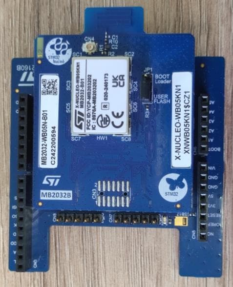
YCP-MB203202
Sep 10, 2024X-NUCLEO-WB05KN1
Equipment Class
DTS - Digital Transmission System
YCP-MB203200
Sep 05, 2024NUCLEO-WB05KZ
Equipment Class
DTS - Digital Transmission System