YJ7-NA09117120V Rechargeable Battery for Power Tools
Stanley Black & Decker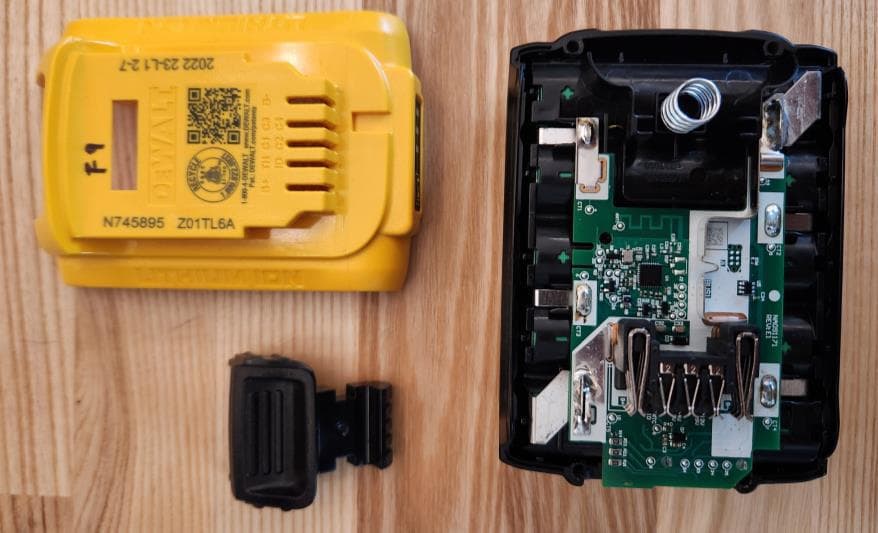
Click to zoom
Application Details
- Equipment Class
- DTS - Digital Transmission System
- Date of Grant
- Oct 08, 2024
- Application Purpose
- Original Equipment
- Date of Application
- Jul 15, 2024
- Equipment Note
- 20V Rechargeable Battery for Power Tools
- Frequency Range
- 2402.00000000 - 2480.00000000
- Company
- Stanley Black & Decker
- Country
- United States
Documents & Files
Document Text
Text extracted from the exhibit documents filed with the FCC. Open a document above to read the original.
Users Manual
NA091171 LMA BT Module Integration Manual Rev 1.1 September 11, 2024 The NA091171 BT module is intended only for use in proprietary Stanley Black and Decker li-ion power tool batteries. It is not intended for sale to third parties and these integration instructions are internal, manufacturing documents. FCC Part 15.212(a)(1) Modular Transmitter Requirements: (i) The module does not have its own shielding. The end-product host must be additionally tested to ensure continued RF compliance when this module is implemented. This testing must include spurious radiated emissions testing. See the host testing guidance in this integration manual. (ii) The module’s data inputs are buffered internal to the Bluetooth IC on the module. (iii) The module contains its own power supply regulation, separate from the host. (iv) The antenna for the module is permanent and etched into the module PCB. The antenna design cannot be changed without a Class II permissive change application for this module. (v) The module has been tested in a stand-alone configuration, independent of any host device. (vi) The module is labeled with its FCC ID and IC number granted by the FCC and ISED after authorization. These identification numbers must appear on a permanent label on the host device. See the labeling instructions in this integration manual. (vii) The module complies with FCC Part 15C, Intentional Radiator requirements. § 15.247 describes operation requirements for the module transmit frequency range of 2400-2483.5 MHz. (viii) The module meets Portable exclusion levels. Module Integration Instructions: The NA091171 module is an intentional radiator and is therefore governed by the FCC rules 47 CFR Part 15, Subpart C. As a Bluetooth radio transmitting in the frequency range 2400-2483.5 MHz, § 15.247 applies. The module is not for sale and only to be used by the Grantee in their proprietary power tools without any modifications to the radio circuitry or PCB antenna. The NA091171 Grant of Authorization is issued as a Limited Modular Approval because the module does not have its own RF shield. As such, deployment of the module in a host device requires a Class II Permissive Change filing for the module. The host product must also be evaluated for RF exposure. A fixed PCB trace antenna is integral to this radio module. This antenna cannot be modified in any way without a Class II Permissive Change filing for the module. Changes or modifications to the module not expressly approved by Stanley Black & Decker could void the user’s authority to operate the device. Host Device Testing Guidance: Because of the Limited Modular Approval of the NA091171 due to the lack of a shield, extra care must be exercised when evaluating all end-product hosts incorporating this module. In particular, the host device must be evaluated using the following test plan to demonstrate compliance with the following: FCC Rule Part: 15.247 Approval FCC ID: YJ7-NA091171 (as a DTS device) Modulation Modes: 1 Mb/s only Maximum power: Low Channel, 1.3 mW Highest Spectral Density: Low Channel The host device must be investigated with the NA091171 module to demonstrate that the module still remains in compliance with the specific rule part. The permissive change test data is intended to verify that original RF conducted data such as worse case power, BW, and density are still compliant and operating correctly at intended levels within the specific host. Additional radiated testing is necessary due to the lack of shield in the module as well as ensure it maintains radiated emissions requirements within the new host. Based on the test data from the original module filing, the following table summarizes the necessary tests to perform for a C2PC to ensure compliance for the NA091171 module when installed within a new host. FCC Rule Part Description Result 15.247(a)(2) Occupied Channel Bandwidth Test Low Channel @ 1 Mb/s 15.247 (b)(3) Transmit Output Power Test Low Channel @ 1 Mb/s. Note Result must be less than or equal to original value to be allowed under a C2PC. 15.247 (e) Power Spectral Density Test Low Channel @ 1 Mb/s 15.247 (d) Out-of-Band Emissions (Band Edge @ 20dB below) Test Lowest and Highest channels at 1 Mb/s for compliance at <= 2400 and >= 2483.5 MHz for both hopping and non-hopping modes. 15.205 15.209 General Field Strength Limits (Restricted Bands & RE Limits) Investigate Low, Mid and High channels for complete radiated emissions using 1 Mb/s. Report either all data or optionally just the worse-case data if a) procedures denote full investigation was made and b) justify that only worse case was provided. Per Part 15.31(m), one frequency near the low-end, one frequency near the middle, and one frequency near the high-end of the frequency range are expected to be evaluated. For this device, the highest aggregate power, and highest power spectral density both occur on the low channel. For radiated emissions, the worst-case channel may be confirmed through an approved investigation. Only the data for worst-case condition among the modes needs to be included in the permissive change report if the overall testing strategy is explained and justified. For the LMA NA091171, since it has no shield, testing of radiated spurious emissions shall cover the 10 th harmonic of the fundamental, per the requirements in Part 15.247, to confirm no additional parasitic or ingress related non-compliant emissions exist. In all cases, a test of each worst-case modulation is required for channels over the frequency range defined in Part 15.33(a). Since the NA091171 module uses only one modulation – only 1 Mb/s needs to be evaluated in this case. If the host device contains additional intentional radiator devices, modular or otherwise, all transmitter devices must be operated simultaneous to ensure that the transmitters can be co-located. The host device is otherwise operated in a typical user mode. The antenna used for this transmitter must not transmit simultaneous…
Text truncated - open the document above for the full version.
Attestation Statements
Kirwan Magdamo Lead Project Engineer 701 East Joppa Road, Towson, MD 21286 T (410) 716 3563 F (410) 716 2961 U.S. Agent Designation for Service of Process (Applicant is Both Grantee and U.S. Agent) TO: American Certification Body, Inc. 313 Park Avenue Suite 300 Falls Church, VA 22046 ATTENTION: FCC Certification – Section 2.911(d)(7) Information This letter is to confirm that the Applicant will also serve as the U.S. Agent for Service of Process as required by 47 CFR 2.911(d)(7). The Applicant acknowledges that they must maintain an agent for no less than one year after terminating all marketing and importation OR the conclusion of any Commission-related proceeding involving the equipment. The Applicant further acknowledges their responsibility to inform the FCC whenever the Designated U.S. Agent information changes. Applicant Company name: Stanley Black & Decker FRN #: 0019980119 Grantee Code: YJ7 Contact Name: Kirwan Magdamo Street Address: 701 East Joppa Road City/Province/Zip: Towson, MD, 21286 Telephone No: 410-716-3563 Email: [email protected] Applicant Signature 1 : Date: April 19, 2024 Signed by (Printed Name/Title): Kirwan Magdamo, Lead Project Engineer 1 - Letters must be placed on appropriate letterhead. The signee for the applicant must be one of the following: Applicant (grantee) contact of record in the FCC’s authorization system, or authorized officers or employee of the applicant (grantee).
Attestation Statements
Kirwan Magdamo Lead Project Engineer 701 East Joppa Road, Towson, MD 21286 T (410) 716 3563 American Certification Body, Inc. 313 Park Avenue Suite 300 Falls Church, VA 22046 To Whom It May Concern: Statement for 47 CFR section 2.911(d)(5)(i) Stanley Black & Decker certifies that as of the date of the application the equipment for which authorization is sought is not “covered” equipment 1 prohibited from receiving an equipment authorization pursuant to section 2.903 of the FCC rules. If the equipment for which the applicant seeks authorization is produced by any of the entities identified on the current Covered List, including affiliates or subsidiaries of the named companies, the applicant must include an explanation on why the equipment is not “covered” equipment. Additional Explanation: <N/A> Statement for 47 CFR section 2.911(d)(5)(ii) _Stanley Black & Decker (“the applicant”) certifies that, as of the date of the filing of this application, the applicant is not identified on the Covered List as an entity producing “covered” equipment. Thank you, By: Kirwan Magdamo (Signature 2 ) (Print name) 1 - The Commission’s Covered List is published by the Public Safety and Homeland Security Bureau and posted on the Commission’s website. This Covered List, which is periodically updated, identifies particular equipment, produced by particular entities, that constitutes “covered” equipment. https://www.fcc.gov/supplychain/coveredlist . 2 - Letters must be placed on appropriate letterhead. Certification Application Attestation Statements Date: September 20, 2024 Title: Lead Project Engineer Company: Stanley Black & Decker Telephone: 410-716-3563
Cover Letter(s)
Kirwan Magdamo Lead Project Engineer 701 East Joppa Road, Towson, MD 21286 T (410) 716 3563 F (410) 716 2961 Authority to Act as Agent Date: April 19, 2024 American Certification Body, Inc. 313 Park Avenue Suite 300 Falls Church, VA 22046 To Whom It May Concern: Kimberly Colbert is authorized to act on our behalf, until otherwise notified, for applications to American Certification Body, Inc. (ACB). We certify that we are not subject to denial of federal benefits, that includes FCC benefits, pursuant to Section 5301 of the Anti-Drug Abuse Act of 1988, 21 U.S.C. 862. Further, no party, as defined in 47 CFR 1.2002 (b), to the application is subject to denial of federal benefits, that includes FCC benefits. We also declare that the information provided to the FCC is true and correct to the best of our knowledge (47 CFR 2.911(d)) and we have been informed of the grantee responsibilities (47 CFR 2.909) with regard to certified equipment. Thank you, Agency Agreement Expiration Date: _____January 17, 2025_____ By: __________________________ _____Kirwan Magdamo___________ (Signature 1 ) (Print name) Title: _____Lead Project Engineer___ 1 - Must be signed by applicant contact given for applicant on the FCC site, or by the authorized agent if an appropriate authorized agent letter has been provided. Letters should be placed on appropriate letterhead. On behalf of: ___Stanley Black & Decker__ (Company Name) Telephone: __410-716-3563__________
Cover Letter(s)
Kirwan Magdamo Lead Project Engineer 701 East Joppa Road, Towson, MD 21286 T (410) 716 3563 F (410) 716 2961 Request for Confidentiality Date: April 29, 2024 Subject: Confidentiality Request for: ___YJ7-NA091171 and 9082A-NA091171___ Pursuant to FCC 47 CFR 0.457(d) and 0.459 and IC RSP-100, Section 12.4, the applicant requests that a part of the subject FCC application be held confidential. Type of Confidentiality Requested Exhibit ☐ Short Term ☒ Permanent Block Diagrams ☐ Short Term --------------------------- External Photos ☐ Short Term ☐ Permanent * 1 Internal Photos ☐ Short Term ☒ Permanent Operation Description/Theory of Operation ☐ Short Term ☐ Permanent Parts List & Placement/BOM ☐ Short Term ☐ Permanent Tune-Up Procedure ☐ Short Term ☒ Permanent Schematics ☐ Short Term --------------------------- Test Setup Photos ☐ Short Term ☐ Permanent * 3 User’s Manual ______Stanley Black & Decker______ has spent substantial effort in developing this product and it is one of the first of its kind in industry. Having the subject information easily available to "competition" would negate the advantage they have achieved by developing this product. Not protecting the details of the design will result in financial hardship. Permanent Confidentiality: The applicant requests the exhibits listed above as permanently confidential be permanently withheld from public review due to materials that contain trade secrets and proprietary information not customarily released to the public. Short-Term Confidentiality for FCC Applications: The applicant requests the exhibits selected above as short term confidential be withheld from public view for a period of __ (specify number of days not to exceed 180) 2 ___ days from the date of the Grant of Equipment Authorization and prior to marketing. This is to avoid premature release of sensitive information prior to marketing or release of the product to the public. Applicant is also aware that they are responsible to notify ACB in the event information regarding the product or the product is made available to the public before the requested period has expired. ACB will then release the documents listed above for public disclosure pursuant to FCC Public Notice DA 04-1705. Short Term Confidentiality for Industry Canada Applications: 1 - The asterisked items (*) require further information to be provided to ACB before permanent confidentiality will be extended to these exhibits. Please refer to FCC KDB 726920 and the specific Document link for D01 found at: https://apps.fcc.gov/oetcf/kdb/forms/FTSSearchResultPage.cfm?switch=P&id=41731 and review section II, 3) regarding specific information that must accompany these requests. 2 - Please refer to https://acbcert.com/documents/misc-docs/Memo-Short-Term-Vs-Standard-Confidentiality.pdf for complete details. Starting May 2022, ISED will recognize short term confidentiality on certain exhibits until the intended date of marketing. The applicant requests the exhibits selected above as short term confidential be withheld from public view until: (specify ISED expiration date / date of marketing) . Sincerely, By: ___Lead Project Engineer______ ____Kirwan Magdamo____ (Signature/Title) (Print Name)
Cover Letter(s)
Kirwan Magdamo Lead Project Engineer 701 East Joppa Road, Towson, MD 21286 T (410) 716 3563 F (410) 716 2961 Request for Modular/Limited Modular Approval Date: June 5, 2024 Subject: Manufacturer’s Declaration for ☐ - Modular Approval ☐ - Split Modular Approval ☒ - Limited Modular Approval ☐ - Limited Split Modular Approval Confidentiality Request for: ______YJ7-NA091171______ 8 Basic Requirements – FCC Part 15.212(a)(1) For Items Marked “NO(*)”, the Limited Module Description Must be Filled Out on the Following Pages Modular Approval Requirement Requirement Met 1. The modular transmitter must have its own RF shielding. This is intended to ensure that the module does not have to rely upon the shielding provided by the device into which it is installed in order for all modular transmitter emissions to comply with FCC limits. It is also intended to prevent coupling between the RF circuitry of the module and any wires or circuits in the device into which the module is installed. Such coupling may result in non-compliant operation. The physical crystal and tuning capacitors may be located external to the shielded radio elements. 15.212(a)(1)(i) ☐ - YES ☒ - NO(*) Details: The NA091171 module does not have its own RF shielding which is why it will have a Limited Modular Approval. 2. The modular transmitter must have buffered modulation/data inputs (if such inputs are provided) to ensure that the module will comply with FCC requirements under conditions of excessive data rates or over-modulation. 15.212(a)(1)(ii) ☒ - YES ☐ - NO(*) Details: Data to the modulation circuit is buffered by the BT radio chip. 3. The modular transmitter must have its own power supply regulation on the module. This is intended to ensure that the module will comply with FCC requirements regardless of the design of the power supplying circuitry in the device into which the module is installed. 15.212(a)(1)(iii) ☒ - YES ☐ - NO(*) Details: The module contains its own power supply regulation. Please refer to schematic filed with this application. 4. The modular transmitter must comply with the antenna and transmission system requirements of §§ 15.203, 15.204(b), 15.204(c), 15.212(a), and 2.929(b). The antenna must either be permanently attached or employ a ‘‘unique’’ antenna coupler (at all connections between the module and the antenna, including the cable). The ‘‘professional installation’’ provision of § 15.203 is not applicable to modules but can apply to limited modular approvals under paragraph 15.212(b). 15.212(a)(1)(iv) ☒ - YES ☐ - NO(*) Details: The module’s antenna is etched into the module PCB and so is permanently attached. 5. The modular transmitter must be tested in a stand-alone configuration, i.e., the module must not be inside another device during testing. This is intended to demonstrate that the module is capable of complying with Part 15 emission limits regardless of the device into which it is eventually installed. Unless the transmitter module will be battery powered, it must comply with the AC line conducted requirements found in Section 15.207. AC or DC power lines and data input/output lines connected to the module must not contain ferrites, unless they will be marketed with the module (see Section ☒ - YES ☐ - NO(*) 15.27(a)). The length of these lines shall be length typical of actual use or, if that length is unknown, at least 10 centimeters to insure that there is no coupling between the case of the module and supporting equipment. Any accessories, peripherals, or support equipment connected to the module during testing shall be unmodified or commercially available (see Section 15.31(i)). 15.212(a)(1)(v) Details: The module was tested stand-alone as shown in test setup photographs filed with this application. Modular Approval Requirement Requirement Met 6. The modular transmitter must be labeled with its own FCC ID number, or use an electron display (see KDB Publication 784748). If using a permanently affixed label with its own FCC ID number, if the FCC ID is not visible when the module is installed inside another device, then the outside of the device into which the module is installed must also display a label referring to the enclosed module. This exterior label can use wording such as the following: “Contains Transmitter Module FCC ID: XYZMODEL1” or “Contains FCC ID: XYZMODEL1.” Any similar wording that expresses the same meaning may be used. The Grantee may either provide such a label, an example of which must be included in the application for equipment authorization, or, must provide adequate instructions along with the module which explain this requirement. In the latter case, a copy of these instructions must be included in the application for equipment authorization. If the modular transmitter uses an electronic display of the FCC identification number, the information must be readily accessible and visible on the modular transmitter or on the device in which it is installed. If the module is installed inside another device, then the outside of the device into which the module is installed must display a label referring to the enclosed module. This exterior label can use wording such as the following: “Contains FCC certified transmitter module(s).” Any similar wording that expresses the same meaning may be used. The user manual must include instructions on how to access the electronic display. A copy of these instructions must be included in the application for equipment authorization. 15.212(a)(1)(vi) ☒ - YES ☐ - NO(*) Details: There is a label on the module as shown in the labeling exhibit filed with this application. Host specific labeling instructions are shown in the installation manual filed with this application. 7. The modular transmitter must comply with all specific rule or operating requirements applicable to the transmitter, including all the conditions provided in the integration instructions by the grantee. A copy of these instructions must be included in the application fo…
Text truncated - open the document above for the full version.
External Photos
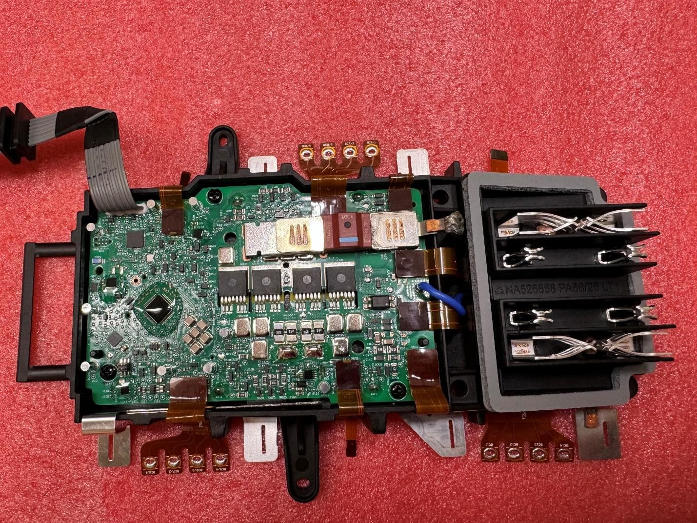
Exploded View Inside Front View Inside Back View Inside Side View PCBA Side View PCBA Top View PCBA Bottom View
ID Label/Location Info
Module top & bottom CAD images:
Internal Photos
Exploded View Inside Front View Inside Back View Inside Side View PCBA Side View PCBA Top View PCBA Bottom View
RF Exposure Info
Page 1 of 6 4840 Winchester Boulevard., Suite #5 Frederick, Maryland 21703 (USA) (301) 216-1500 [email protected] April 24, 2024 Test Letter #: 18510-01 REV 0 (Created with Reference to WL Report # 18508) Applicant: Stanley Black & Decker, Inc. Exempt RF Device: Battery Pack Module (NA091171) (BLE, Single Limited Module) FCC ID: YJ7-NA091171 ISED ID: 9082A-NA091171 EUT Summary: The NA091171 Battery Pack Module is categorically excluded from SAR testing. Time-Averaged Exclusion Threshold for FCC: Reference: KDB 447498 DO1 General RF Exposure Guidance v06. -- SAR evaluation for general population exposure conditions, by measurement or simulation, is not required when the corresponding SAR Test Exclusion Threshold condition(s), listed below, are satisfied. These test exclusion conditions are based on source-based time-averaged maximum conducted output power of the RF channel requiring evaluation, adjusted for tune-up tolerance, and the minimum test separation distance required for the exposure conditions. In accordance with Section 4.3.1, of the referenced document, the following formula may be used to calculate the exclusion of SAR Testing: where, a) f (GHz) is the RF channel transmit frequency in GHz b) power and distance shall be rounded to the nearest mW and mm before calculation. c) the result is rounded to the nearest mW and mm before calculation. d) when the minimum test separation distance is < 5mm, a distance of 5mm is used e) the values of 3.0 and 7.5 are the final numerical thresholds, these values are unitless. Page 2 of 6 4840 Winchester Boulevard., Suite #5 Frederick, Maryland 21703 (USA) (301) 216-1500 [email protected] Time-Averaged Exclusion Threshold for ISED Canada: Reference: RSS-102, Issue 6 (12/2023) Radio Frequency (RF) Exposure Compliance of Radiocommunication Apparatus (All Frequency Bands). -- SAR evaluation is required if the separation distance between the user and/or bystander and the antenna and/or radiating element of the device is less than or equal to 20 cm, except when the device operates at or below the applicable output power level (adjusted for tune-up tolerance) for the specified separation distance defined in RSS-102. These limits are provided below. Exclusion Limit for ISED Canada, Interpolated: The limits of Table 1, as provided in RSS-102, Issue 5 are based on RF port conducted power, or EIRP, whichever is higher. The EUT transmitter has a frequency of range of 2402 MHz to 2480 MHz As such, the interpolated limit shall be calculated from 2480 MHz, as this frequency produces the strictest limit. Additionally, the following equation shall by employed to interpolate the proper exclusion threshold: where, x 1 and y 1 is the first set of coordinates (e.g., 2450 MHz and 3 mW, respectively). x 2 and y 2 is the second set of coordinates (e.g., 3500 MHz and 2 mW, respectively). x is the EUT transmit frequency of 2480 MHz y is the final limit (e.g., interpolated value). Page 3 of 6 4840 Winchester Boulevard., Suite #5 Frederick, Maryland 21703 (USA) (301) 216-1500 [email protected] therefore, y = 3 + (2480 – 2450) * ((2 – 3) ÷ (3500 – 2450)) y = 2.97 mW further, 2.97 mW is the final exclusion limit for the BLE transmitter 2.97 mW = 4.73 dBm where, dBm = 10LOG(mW) dBm = 10LOG(2.97) dBm = 4.73 finally, 2.97 mW is the SAR testing exemption limit for ISED Canada (time-averaged power) 4.73 dBm is the SAR testing exemption limit for ISED Canada (time-averaged power) Exclusion Threshold Summary (for both markets): FCC = 3.0 (unitless) ISED = 2.97 mW Page 4 of 6 4840 Winchester Boulevard., Suite #5 Frederick, Maryland 21703 (USA) (301) 216-1500 [email protected] EUT Transmitter Details: The EUT has a peak output power, conducted at the antenna port, that measured +1.25 dBm. The manufacturer has declared a tune-up tolerance of ± 1.0 dB. The EUT employes a PCB trace antenna with a peak gain of -5.44 dBi. As a worst-case evaluation, the antenna gain value of 0.0 dBi shall be used. as such, 1.25dBm + 1.0dB + 0.0dBi = 2.25 dBm EIRP where, 2.25 dBm = the peak EIRP of the transmitter, not time-average mW = 10 (dBm ÷ 10) therefore, 2.25 dBm = 1.68 mW (shall be rounded to 2 mW). 2 mW = maximum power of RF channel, including tune-up tolerance Exclusion Results for FCC: The earlier noted compliance formula, referenced to KDB 447498 DO1, shall be employed: as such, (2mW ÷ 5mm) · (√2.48GHz) = 0.53 finally, because 0.53 is less than 3.0, the EUT is categorically excluded from SAR testing. Page 5 of 6 4840 Winchester Boulevard., Suite #5 Frederick, Maryland 21703 (USA) (301) 216-1500 [email protected] Exclusion Results for ISED Canada: The EUT transmitter has a peak EIRP of +2.25 dBm (not time-averaged), which is equal to 1.68 mW. IN this case 1.68 mW shall be rounded to 2mW. therefore, 2.25 dBm = 1.68 mW (shall be rounded to 2 mW). 2 mW = maximum power of RF channel, adjusted tune-up tolerance The ISED Canada limitation for SAR exclusion is: 2.97 mW (time-averaged threshold). finally, because 2 mW is less than 2.97 mW, the EUT is categorically excluded from SAR testing. Conclusion: The FCC time-averaged SAR Exclusion limit is 3.0 (numerical) The EUT has a calculated numerical value of 0.53. Because 0.53 is less than 3.0, the EUT is categorically excluded from SAR testing. The ISED Canada time-averaged SAR Exclusion limit is 2.97 mW. The EUT has a peak EIRP of 2.0 mW Because 2.0 mW is less than 2.97 mW, the EUT is categorically excluded from SAR testing. Overall, the NA091171 Battery Pack Module is categorically excluded from SAR testing. In both cases, the transmitter peak power meets the average exclusion limit. Page 6 of 6 4840 Winchester Boulevard., Suite #5 Frederick, Maryland 21703 (USA) (301) 216-1500 [email protected] The Washington Laboratories, Ltd., test facility is located at 4840 Winchester Boulevard, Frederick MD 21703 (USA). Washington Laboratories, Ltd. has been accepted by the FCC and approved by ANAB under Certificate AT-1448 as an independent test laboratory. These tests are accredited and me…
Text truncated - open the document above for the full version.
Test Report
ANTENNA TEST REPORT for the STANLEY BLACK & DECKER, INC. FCC ID: YJ7-NA091171 IC ID: 9082A-NA091171 WLL REPORT# 18681-01 REV 3 Prepared for: Stanley Black & Decker, Inc. 701 E. Joppa Road Towson, Maryland 21286 Prepared By: Washington Laboratories, Ltd. 4840 Winchester Boulevard Frederick, Maryland 21703 Testing Certificate AT-1448 Certificates and reports shall not be reproduced except in full, without the written permission of Washington Laboratories, Ltd Stanley Black & Decker, Inc. NA091171 (Trace Antenna) Antenna Test Report WLL Report 18459-01 Rev 3 Page-2 of 22 Antenna Test Report for the Stanley Black & Decker, Inc. FCC ID: YJ7-NA091171 IC ID: 9082A-NA091171 WLL Report# 18681-01 Rev 3 April 24, 2024 Prepared by: ___________________________ Ryan Mascaro RF Test Engineer Reviewed by: ____________________________ Steven D. Koster President Stanley Black & Decker, Inc. NA091171 (Trace Antenna) Antenna Test Report WLL Report 18459-01 Rev 3 Page-3 of 22 Abstract This report has been prepared on behalf of Stanley Black & Decker, Inc. to document the testing results of the Bluetooth Antenna that is contained as part of the applicant’s transmitter assembly, seeking authorization under FCC ID: YJ7-NA091171. The information provided within this report is only applicable to the device herein documented as the EUT. Testing was performed in the Free-space Anechoic Chamber Test-site (FACT) 3m chamber of Washington Laboratories, Ltd., located at: 4840 Winchester Boulevard, Suite #5., Frederick, MD 21703. Revision History Description of Change Date Rev 0 Initial Release April 24, 2024 Rev 1 Minor grammatical corrections May 21, 2024 Rev 2 Expanded the details of section 3.1.2 June 7, 2024 Rev 3 Co-sign corrections for final calculation June 17, 2024 Stanley Black & Decker, Inc. NA091171 (Trace Antenna) Antenna Test Report WLL Report 18459-01 Rev 3 Page-4 of 22 Table of Contents 1 Introduction ..................................................................................................................................... 6 1.1 Test Scope ................................................................................................................................... 6 1.2 Contract Information ................................................................................................................... 6 1.3 Test and Support Personnel ........................................................................................................ 6 1.4 Test Location .............................................................................................................................. 6 1.5 Environmental Conditions .......................................................................................................... 6 2 Equipment Under Test, Antenna..................................................................................................... 7 2.1 EUT Identification & Description .............................................................................................. 7 2.2 Test Configuration .................................................................................................................... 10 2.2.1 Test Equipment Used ........................................................................................................ 10 3 Test Results ................................................................................................................................... 11 3.1 Antenna Pattern ......................................................................................................................... 11 3.1.1 Test Procedure Summary .................................................................................................. 11 3.1.2 Radiated Data Reduction and Reporting ........................................................................... 11 3.1.3 Complete Test Data..........................................................................................…
Text truncated - open the document above for the full version.
Contact Information
Applicant
Kirwan Magdamo
[email protected](410)716-3563
Technical Contact
Non-Technical Contact
Stanley Black & DeckerKirwan Magdamo
[email protected]410-716-3563
Test Firm
Washington Laboratories, Ltd.Steve Koster
Technical Specifications
| # | Rule Parts | Frequency Range | Power Output |
|---|---|---|---|
| 1 | 15C | 2.40 GHz - 2.48 GHz | 1.30 mW |
Other Applications from Stanley Black & Decker
YJ7-NA382408
Aug 18, 2024Bluetooth Radio Module for DeWalt Li-Ion Rechargable Batteries
Equipment Class
DTS - Digital Transmission System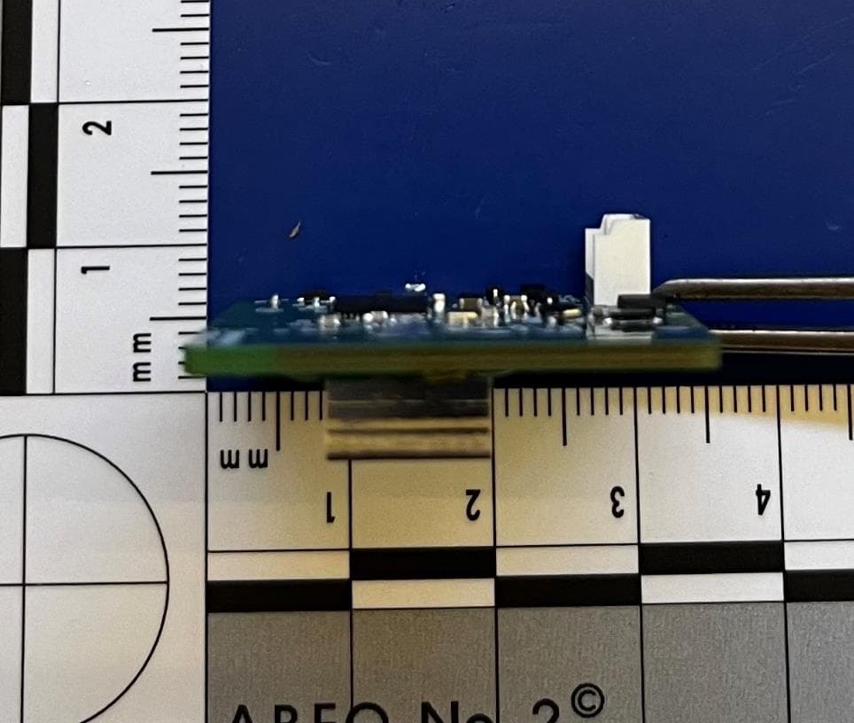
YJ7-NA080801
Aug 12, 2024Proprietary Bluetooth Radio Module
Equipment Class
DTS - Digital Transmission System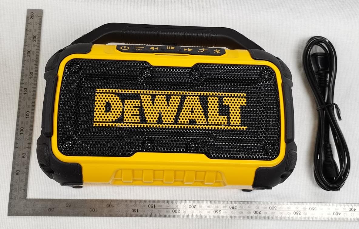
YJ7DCR010B
Nov 07, 2023Bluetooth Speaker
Equipment Class
DSS - Part 15 Spread Spectrum Transmitter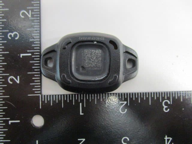
YJ7-DCE045
Jul 30, 2023BLE Tag
Equipment Class
DTS - Digital Transmission System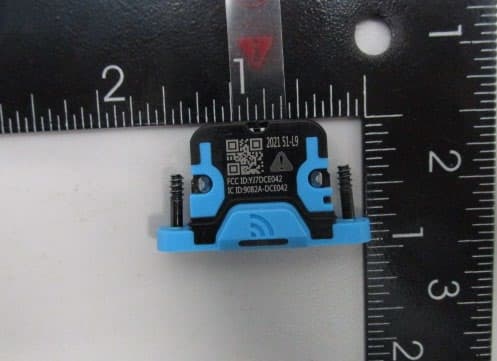
YJ7DCE042
Jan 05, 2023DCE042 Bluetooth Audit Chip
Equipment Class
DTS - Digital Transmission System