YLF-2010-08-APU2Sapphire
7signal
Click to zoom
Application Details
- Equipment Class
- DTS - Digital Transmission System
- Date of Grant
- Nov 17, 2010
- Application Purpose
- Original Equipment
- Date of Application
- Nov 16, 2010
- Equipment Note
- Sapphire
- Frequency Range
- 2412.00000000 - 2462.00000000
- Company
- 7signal
- Country
- United States
Documents & Files
Document Text
Text extracted from the exhibit documents filed with the FCC. Open a document above to read the original.
Users Manual
1 7signal Sapphire Carat User Guide 2 Administrativia FCC Warning The radiated output power of the 7signal Sapphire Eye complies with the FCC RF exposure limits. To avoid the possibility of exceeding the FCC radio frequency exposure limits, a distance of at least 20 cm should be kept with the user and the device while operating. NOTE TO THE USER Any uninstructed modification to the 7signal products may result in violation of FCC requirements. 3 Table of Contents THE 7signal Sapphire WQA SOLUTION ................................................................................................. 7 System overview .......................................................................................................................................................................8 System components ................................................................................................................................................................8 SAPPHIRE EYE .............................................................................................................................................. 9 SAPPHIRE CARAT ...................................................................................................................................... 11 SONAR .......................................................................................................................................................... 12 SAPPHIRE LOUPE ...................................................................................................................................... 13 CARAT MANAGEMENT INTERFACE ....................................................................................................... 14 Menus ............................................................................................................................................................................................. 14 ON CONFIGURING OF 7SIGNAL SAPPHIRE CARAT ........................................................................... 17 Automated Tests .................................................................................................................................................................... 17 Access Rights ............................................................................................................................................................................ 18 USER MANAGEMENT ................................................................................................................................. 19 User groups and object permissions ........................................................................................................................ 19 User group hierarchy .......................................................................................................................................................... 19 User access levels .................................................................................................................................................................. 20 User group and user management ............................................................................................................................. 20 User groups ................................................................................................................................................................................ 20 Users ............................................................................................................................................................................................... 22 WIRELESS NETWORKS AND TARGET NETWORKS ............................................................................. 25 Addition of networks to be monitored .................................................................................................................. 25 Addition of a network location ................................................................................................................................... 25 Hidden networks .................................................................................................................................................................... 26 Removal of a network ........................................................................................................................................................ 27 SETTING UP A MONITORING STATION ................................................................................................ 30 States of Monitoring Stations ....................................................................................................................................... 30 Adding a monitoring station .......................................................................................................................................... 30 Monitoring station settings ............................................................................................................................................ 31 Activation of monitoring station................................................................................................................................ 32 Floor plan.................................................................................................................................................................................... 32 Updates to a management station's software................................................................................................... 33 4 CREATION AND USE OF AN ENCRYPTION KEY .................................................................................. 35 On key types ............................................................................................................................................................................. 35 On different methods and implementations ..................................................…
Text truncated - open the document above for the full version.
External Photos
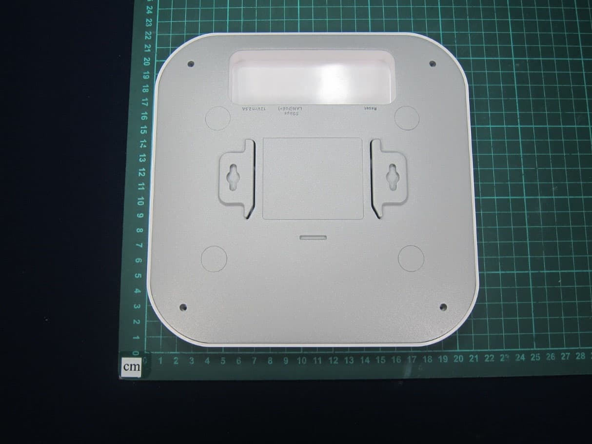
7signal Sapphire Eye - Top 7signal Sapphire Eye - Bottom 7signal Sapphire Eye - Sideways 7signal Sapphire Eye - Connectors 7signal Sapphire Eye - Opposite to connectors 7signal Sapphire Eye - Top lid removed NOTE: The customer does not have to remove the lid in any use case. NOTE: The external antenna is disabled for US markets. 7signal Sapphire Eye – Top lid connectors (inside) 7signal Sapphire Eye – Battery chamber
ID Label/Location Info
FCC ID sticker location on 7signal Sapphire Eye FCC ID YLF-
Internal Photos
7signal Sapphire Eye - Explosion 7signal Sapphire Eye - RF circuit – top 7signal Sapphire Eye - RF circuit – bottom 7signal Sapphire Eye - Computer card – bottom without wlan card 7signal Sapphire Eye - Computer card bottom with a wlan card. NOTE: The wlan card is 3 rd party FCC approved. 7signal Sapphire Eye - Computer card – bottom connectors 7signal Sapphire Eye - Computer card – top 7signal Sapphire Eye - Computer card – top with a shield 7signal Sapphire Eye - Computer card – bottom with the battery connector 7signal Sapphire Eye - Botton antenna panel - top 7signal Sapphire Eye - Botton antenna panel - botton 7signal Sapphire Eye – Side antenna panel - top 7signal Sapphire Eye – Side antenna panel - bottom 7signal Sapphire Eye – Antenna array mechanics 7signal Sapphire Eye – Middle lid - bottom 7signal Sapphire Eye – Middle lid - bottom 7signal Sapphire Eye – Outside cover for antenna array 7signal Sapphire Eye – Antenna array assembled 7signal Sapphire Eye – Top covers and computer card removed, RF card with shield visible.
RF Exposure Info
1 (1) SGS Fimko Ltd Särkiniementie 3, PO Box 30 FI-00211 Helsinki, Finland t. +358 9 696 361 f. +358 9 692 5474 www.fi.sgs.com Business ID 0978538-5 Member of the SGS Group (SGS SA) RF EXPOSURE ANALYSIS Product FCC ID WLAN Network Monitoring Device YLF-2010-08-APU2 This device is designed to be mounted on a ceiling of the room. Persons must keep a separation distance of at least 20 cm while it is in operation. Analysis for FCC The equipment transmits in the 2400 – 2483,5 MHz frequency range and therefore the applicable threshold is calculated as stated in FCC document KDB 447498 by using the formula f 60 (where f is a highest frequency in used) mW2.24 4835.2 60 = Output power considerations: Max. E.I.R.P value: 13.88 dBm = 24.43 mW (Value is taken from the test report number: 257245-4. Value contains conducted output power and antenna gain.) RF exposure evaluation: 22 4 ... 4R PRIE R GP S ππ = ∗ = E.I.R.P (dBm) E.I.P.R (mW) Evaluation distance (cm) S – power density (mW/cm 2 ) 13.88 24.43 20 0.00486 Result: Equipment complies with the FCC limits for maximum permissible exposure
Test Report
Reference number: 257245-4 Page 2 of 61 Table of Contents PRODUCT DESCRIPTION 3 Equipment Under Test (EUT) 3 Description of the EUT 3 Ratings and declarations 3 P ower Supply 3 Mechanical Size of the EUT 4 Cables 4 Peripherals 4 Samples 4 GENERAL REMARKS 5 Disclaimer 5 SUMMARY OF TESTING 6 Photographs of the EUT 7 TEST RESULTS 9 Conducted Emissions In The Frequency Range 150 kHz - 30 MHz 9 Maximum Peak Conducted Output Power 12 Transmitter Radiated Emissions 30 – 1000 MHz 16 Transmitter Radiated Emissions 1 – 26.5 GHz 23 Receiver Radiated Emissions 30 – 1000 MHz 26 Receiver Radiated Emissions 1 – 26.5 GHz 28 Transmitter Conducted Emissions 30 MHz – 26.5 GHz 29 Transmitter Band Edge Measurement 42 6dB Bandwidth 47 Power Spectral Density 54 LIST OF TEST EQUIPMENTS 61 Reference number: 257245-4 Page 3 of 61 Product Description PRODUCT DESCRIPTION Equipment Under Test (EUT) Sapphire Eye-radio Unit Brand: 7signal Product number: A10095 Type: 7signal Sapphire-Eye Serial no: 09380002 HW version: 2.0 SW version: 3.32 FCC ID number: YLF-2010-08-APU2 Description of the EUT The EUT is a wireless radio unit and it is a part of 7signal Sapphire Wireless Quality Advancement (WQA) System which measures and analyzes quality of WLAN. Classification of the device Fixed mounted device Mobile Device (Human body distance > 20cm) Portable Device (Human body distance < 20cm) Modifications Incorporated in the EUT No modifications were applied to the EUT during testing Ratings and declarations Operating Frequency Range: 2400.0 - 2483.5 MHz Channels: 11 Channel separation: 5 MHz Channel bandwidth: 22 MHz Effective radiated or conducted power: <100 mW EIRP Modulation: OFDM, DSSS Transmission rate: max 11 MBit/s @ 802.11b max 54 MBit/s @ 802.11g Antenna type and gain: Directional plane antenna Maximum gain 7.7 dBi Power Supply Rated voltage: 110 V Rated current: 1.5 A Rated frequency: 60 Hz Rated power: --- Reference number: 257245-4 Page 4 of 61 Product Description Mechanical Size of the EUT Height: 174 mm Diameter:220mm Cables Cable: Length: Type: Mains cable 1.2 m Unshielded, L/N/PE DC cable 1.2 m Unshielded, +/- Peripherals Peripheral Manufacturer Model S/N Connection to the EUT AC adapter HIPRO HP-O2040D43 rev. 01 --- DC input Samples Sample No. 1: The equipment uses its integral antenna. Sample No. 2: Antenna was removed and measurement cable was connected to the EUT by using temporary antenna connector. Reference number: 257245-4 Page 5 of 61 General remarks GENERAL REMARKS Disclaimer This test report is issued under SGS Fimko general terms of delivery (available on request and accessible at www.fi.sgs.com ). Attention is drawn to the limitations of liability, indemnification and jurisdictional issues defined therein. Unless otherwise stated: (a) the results shown in this document refer only to the sample(s) tested and (b) such sample(s) are retained for three months. This document cannot be reproduced except in full, without prior approval of SGS Fimko. Any unauthorized alteration, forgery or falsification of the content or appearance of this report is unlawful and offenders may be prosecuted to the fullest extent of the law Reference number: 257245-4 Page 6 of 61 Summary of Testing SUMMARY OF TESTING FCC Rules Description of Test Result §15.207(a) Conducted Emissions PASS §15.247(b)(3) Maximum Peak Conducted Output Power PASS §15.247(a)(2) 6 dB Bandwidth PASS §15.247(d) 100 kHz Bandwidth of Frequency Band Edges PASS §15.209(a) §15.247(d) Radiated Emissions PASS §15.247(e) Power Spectral Density PASS Description of Test Modes The sample is using WLAN technology according IEEE 802.11 b/g. In preliminary tests the different data rates of 802.11b and 802.11g modes were not given much difference to measurement results. So the highest data rates of both modes were chosen to tested. There are two testing modes in the test report. Mode A: IEEE 802.11b 11 MBit/s DSSS Mode B: IEEE 802.11g 54 MBit/s OFDM Test are performed on three channel in both modes Channel Channel Number Frequency (MHz) LOW CH 1 2412.0 MID CH 5 2437.0 HIGH CH 11 2462.0 Test Facility Testing Location / address: FCC registration number: 90598 SGS Fimko Ltd Särkiniementie 3 FI-00210, HELSINKI FINLAND Testing Location / address: FCC registration number: 178986 Industry Canada registration number: 8708A-2 SGS Fimko Ltd Karakaarenkuja 4 FI-02610, ESPOO FINLAND Reference number: 257245-4 Page 7 of 61 Summary of Testing Photographs of the EUT Picture 1. The EUT and test set-up for conducted emission test Reference number: 257245-4 Page 8 of 61 Summary of Testing Picture 2. The EUT and test set-up for radiated emission test. Reference number: 257245-4 Page 9 of 61 Conducted Emission Test TEST RESULTS Conducted Emissions In The Frequency Range 150 kHz - 30 MHz Standard: ANSI C63.4 (2003) Tested by: NTO Date: 18.2.2010 Humidity: 21 % Temperature: 22 °C Barometric pressure: 1011mbar Measurement uncertainty: ±2.3 dB Level of confidence 95 % (k = 2) FCC Rule: 15.207(a) For equipment that is designed to be connected to the public utility (AC) power line, the radio frequency voltage that is conducted back onto the AC power line on any frequency or frequencies within the band 150 kHz to 30 MHz shall not exceed the limits in the following table, as measured using a 50 μH/50 ohms line impedance stabilization network (LISN). Compliance with the provisions of this paragraph shall be based on the measurement of the radio frequency voltage between each power line and ground at the power terminal. The lower limit applies at the band edges Reference number: 257245-4 Page 10 of 61 Conducted Emission Test Test results Transmitter with Mode B on middle channel -10 0 20 40 60 80 100 120 150k 300 400 500 800 1M2M3M4M 5M 6 8 10M20M30M L e v e l i n d B O V Frequency in Hz F CC Part 15 Class B Voltage on Mains QP.LimitLine F CC Part 15 Class B Voltage on Mains AV.LimitLine Preview Result 1Preview Result 2 Final Result 1Final Result 2 Figure 1 The measured curves with peak- and…
Text truncated - open the document above for the full version.
Test Setup Photos
1 (3) Test setup photographs. Radiated emissions test setup frequency range 30 – 1000 MHz. 2 (3) Radiated emissions test setup frequency range 1 – 26 GHz. 3 (3) Conducted emission test setup.
Contact Information
Applicant
Ted Schneider(CTO)
Technical Contact
7signal OyAnton Puolakka
Helsinki · Finland
Test Firm
SGS Fimko OyJanne Nyman
Technical Specifications
| # | Rule Parts | Frequency Range | Power Output |
|---|---|---|---|
| 1 | 15C | 2.41 GHz - 2.46 GHz | 4.00 mW |
Other Applications from 7signal
YLF7S6300
Oct 30, 2023Wi-Fi 6/6E Sensor
Equipment Class
6XD - 15E 6 GHz Low Power Indoor Client
YLF-INDR-EYE01
Mar 18, 2014Access point
Equipment Class
DTS - Digital Transmission System
YLF-ABGN-EYE-APU3
Aug 17, 20117Signal Sapphire
Equipment Class
NII - Unlicensed National Information Infrastructure TX
YLF-ABG-EYE-APU2
Apr 14, 2011Sapphire
Equipment Class
NII - Unlicensed National Information Infrastructure TX