YLI-HSNHI2iTwinkle Wifi Module
H.S. CRAFT MANUFACTURING CO.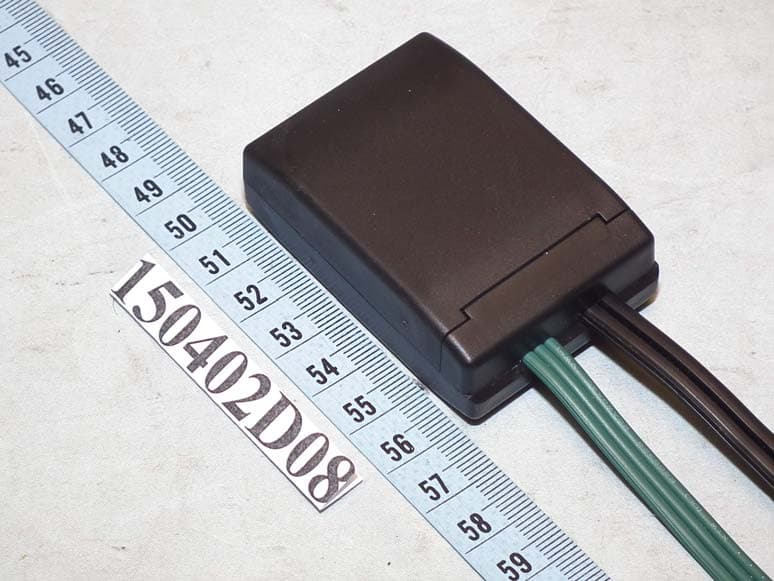
Click to zoom
Application Details
- Equipment Class
- DTS - Digital Transmission System
- Date of Grant
- May 17, 2015
- Application Purpose
- Original Equipment
- Date of Application
- May 17, 2015
- Equipment Note
- iTwinkle Wifi Module
- Frequency Range
- 2412.00000000 - 2462.00000000
- Company
- H.S. CRAFT MANUFACTURING CO.
- Country
- Taiwan
Documents & Files
Document Text
Text extracted from the exhibit documents filed with the FCC. Open a document above to read the original.
Users Manual
36 LED Light Set IMPORTANT SAFETY INSTRUCTIONS 36 LED G35 iTwinkle light show Item Number: 00851 00853 UL Model No.: NHI-G35-36(0.25) When using electrical products, basic precautions should always be followed including the following: READ AND FOLLOW ALL SAFETY INSTRUCTIONS • This is an electrical product - not a toy! To avoid the risk of fire, burns, personal injury and electric shock it should not be played with or placed where small children can reach it. • Do not use seasonal products outdoors unless marked suitable for indoor and outdoor use. When products are used in outdoor applications, connect the product to a Ground Fault Circuit Interrupting (GFCI) outlet. If one is not provided contact a qualified electrician for proper installation. • This seasonal use product is not intended for permanent installation or use. • Do not mount or place near gas or electric heaters, fireplaces, candles or other similar sources of heat. • Do not secure the wiring of the product with staples or nails, or place on sharp hooks or nails. • Do not let lamps rest on the supply cord or on any wire. • Unplug the product when leaving the house, when retiring for the night, or if left unattended. • Do not use this product for other than its intended use. • Do not hang ornaments or other objects from cord, wire, or light string. • Do not close doors or windows on the product or extension cord as this may damage the wire insulation. • Do not cover the product with cloth, paper or any material not part of the product when in use. • This product has a polarized plug (one blade is wider than the other) as a feature to reduce the risk of electric shock. This plug will fit in a polarized outlet only one way. If the plug does not fit fully in the outlet, reverse the plug. If it still does not fit, contact a qualified electrician. Do not use with an extension cord unless plug can be fully inserted. Do not alter or replace the plug. • Read and follow all instructions that are on the product or provided with the product. SAVE THESE INSTRUCTIONS USE AND CARE INSTRUCTIONS • When the product is placed on a live tree, the tree should be well maintained and fresh. Do not place on live trees in which the needles are brown or break off easily. Keep the tree holder filled with water. • If the product is placed on a tree, the tree should be well secured and stable. • Before using, or reusing, inspect product carefully. Discard any products that have cut, damaged or frayed wire insulation or cords, cracks in the lampholders or enclosures, loose connections, or exposed copper wire. • When storing the product, carefully remove the product from wherever it is placed, including trees, branches, or bushes, to avoid any undue strain or stress on the product conductors, connections and wires. • When not in use, store neatly in a cool, dry location protected from sunlight. Install Class 2 Power Supply To String: Fig. 1 Fig. 2 Fig. 3 NOTE: Use only this GE branded, Class 2 Power Supply, Model SA3A-050- 3000, manufactured by TDC that was provided with this product. DO NOT use this adapter with any other product. 1. Remove the Power Supply from its packing box. 2. The LED string is fitted with a 2-pronged fitting. 3. Align the notch in fitting with the inner tab on end of Power Supply {Fig. 1} 4. Fully insert the fitting into the Power Supply {Fig. 2} 5. Screw the collar completely onto the Power Supply turning clockwise {Fig. 3} NOTE: LEDs are non-replaceable. Tampering with this set voids the warranty. CAUTION: • To reduce the risk of fire and electric shock: a) Do not install on trees having needles, leaves or branch coverings of metal or materials which look like metal, and b) Do not mount or support strings in a manner that can cut or damage wire insulation. This device complies with Part 15 of the FCC Rules. Operation is subject to the following two conditions: ▪ this device may not cause harmful interference, and ▪ this device must accept any interference received, including interference that may cause undesired operation. Modifications not approved by the party responsible for compliance could void user’s authority to operate the equipment. NOTE: This equipment has been tested and found to comply with the limits for Class B digital device, pursuant to Part 15 of the FCC Rules. These limits are designed to provide reasonable protection against harmful interference in a residential installation. This equipment generates, uses and can radiate radio frequency energy and, if not installed and used in accordance with the instructions, may cause harmful interference to radio or television reception, which can be determined by turning the equipment off and on, the user is encouraged to try to correct the interference by one or more of the following measures: * Reorient or relocate the receiving antenna. * Increase the separation between the equipment and the receiver. * Connect the equipment into an outlet on a circuit different from that to which the receiver is connected. * Consult the dealer or an experienced radio/TV technician for help. FCC Caution: Any changes or modifications not expressly approved by the party responsible for compliance could void the user's authority to operate this equipment. This transmitter must not be co-located or operating in conjunction with any other antenna or transmitter. Radiation Exposure Statement: This equipment complies with FCC radiation exposure limits set forth for an uncontrolled environment. This equipment should be installed and operated with minimum distance 20cm between the radiator & your body. Note: The country code selection is for non-US models only and is not available for US models. Models marketed in the United States operate only on US Channels. This is not a toy, for decorative use only For Indoor and Outdoor Use 120V 60Hz If you need assistance please call our toll free number: 1-877-398-7337 and a customer support representative will assist you. Holiday season Nov 14 to Dec 23:…
Text truncated - open the document above for the full version.
External Photos
Page 1 CONSTRUCTION PHOTOS OF EUT
Internal Photos
Page 2 Page 3 Page 4
RF Exposure Info
Report No.:SA150402D08 Page No. 1 / 6 Report Format Version: 6.1.1 RF Exposure Report Report No.: SA150402D08 FCC ID: YLI-HSNHI2 Test Model: NHI-85X Received Date: Apr. 2, 2015 Test Date: May 4 ~ 7, 2015 Issued Date: May 11, 2015 Applicant: H.S. CRAFT MANUFACTURING CO. Address: 9F, NO. 35, GUANG FU N. ROAD, TAIPEI, TAIWAN Issued By: Bureau Veritas Consumer Products Services (H.K.) Ltd., Taoyuan Branch Lab Address: No. 47-2, 14th Ling, Chia Pau Vil., Lin Kou Dist., New Taipei City, Taiwan (R.O.C.) This report is for your exclusive use. Any copying or replication of this report to or for any other person or entity, or use of our name or trademark, is permitted only with our prior written permission. This report sets forth our findings solely with respect to the test samples identified herein. The results set forth in this report are not indicative or representative of the quality or characteristics of the lot from which a test sample was taken or any similar or identical product unless specifically and expressly noted. Our report includes all of the tests requested by you and the results thereof based upon the information that you provided to us. You have 60 days from date of issuance of this report to notify us of any material error or omission caused by our negligence, provided, however, that such notice shall be in writing and shall specifically address the issue you wish to raise. A failure to raise such issue within the prescribed time shall constitute your unqualified acceptance of the completeness of this report, the tests conducted and the correctness of the report contents. Unless specific mention, the uncertainty of measurement has been explicitly taken into account to declare the compliance or non-compliance to the specification. The report must not be used by the client to claim product certification, approval, or endorsement by TAF or any government agencies. Report No.:SA150402D08 Page No. 2 / 6 Report Format Version: 6.1.1 Table of Contents Release Control Record .................................................................................................................................. 3 1 Certificate of Conformity ...................................................................................................................... 4 2 RF Exposure .......................................................................................................................................... 5 2.1 Limits For Maximum Permissible Exposure (MPE) ............................................................................. 5 2.2 Mpe Calculation Formula .................................................................................................................... 5 2.3 Classification ....................................................................................................................................... 5 3 Calculation Result Of Maximum Conducted Power .......................................................................... 6 Report No.:SA150402D08 Page No. 3 / 6 Report Format Version: 6.1.1 Release Control Record Issue No. Description Date Issued SA150402D08 Original release. May 11, 2015 Report No.:SA150402D08 Page No. 4 / 6 Report Format Version: 6.1.1 1 Certificate of Conformity Product: iTwinkle Wifi Module Brand: GE Test Model: NHI-85X Sample Status: Mass-Production Applicant: H.S. CRAFT MANUFACTURING CO. Test Date: May 4 ~ 7, 2015 Standards: FCC Part 2 (Section 2.1091) KDB 447498 D03 IEEE C95.1 The above equipment has been tested by Bureau Veritas Consumer Products Services (H.K.) Ltd., Taoyuan Branch, and found compliance with the requirement of the above standards. The test record, data evaluation & Equipment Under Test (EUT) configurations represented herein are true and accurate accounts of the measurements of the sample’s EMC characteristics under the conditions specified in this report. Prepared by : , Date:May 11, 2015 Annie Chang / Supervisor Approved by : , Date:May 11, 2015 Rex Lai / Assistant Manage Report No.:SA150402D08 Page No. 5 / 6 Report Format Version: 6.1.1 2 RF Exposure 2.1 Limits For Maximum Permissible Exposure (MPE) Frequency Range (MHz) Electric Field Strength (V/m) Magnetic Field Strength (A/m) Power Density (mW/cm 2 ) Average Time (minutes) Limits For General Population / Uncontrolled Exposure 300-1500 ... ... F/1500 30 1500-100,000 ... ... 1.0 30 F = Frequency in MHz 2.2 MPE Calculation Formula Pd = (Pout*G) / (4*pi*r 2 ) where Pd = power density in mW/cm 2 Pout = output power to antenna in mW G = gain of antenna in linear scale Pi = 3.1416 R = distance between observation point and center of the radiator in cm 2.3 Classification The antenna of this product, under normal use condition, is at least 20cm away from the body of the user. So, this device is classified as Mobile Device. Report No.:SA150402D08 Page No. 6 / 6 Report Format Version: 6.1.1 3 Calculation Result Of Maximum Conducted Power Frequency Band (MHz) Max Power (dBm) Antenna Gain (dBi) Distance (cm) Power Density (mW/cm 2 ) Limit (mW/cm 2 ) 2412-2462 18.64 -10.24 20 0.0014 1 --- END ---
Test Report
Report No.: RF150402D08 Page No. 1 / 50 Report Format Version: 6.1.1 FCC Test Report Report No.: RF150402D08 FCC ID: YLI-HSNHI2 Test Model: NHI-85X Received Date: Apr. 2, 2015 Test Date: May 4 ~ 7, 2015 Issued Date: May 11, 2015 Applicant: H.S. CRAFT MANUFACTURING CO. Address: 9F, NO. 35, GUANG FU N. ROAD, TAIPEI, TAIWAN Issued By: Bureau Veritas Consumer Products Services (H.K.) Ltd., Taoyuan Branch Lab Address: No. 47-2, 14th Ling, Chia Pau Vil., Lin Kou Dist., New Taipei City, Taiwan (R.O.C.) This report is for your exclusive use. Any copying or replication of this report to or for any other person or entity, or use of our name or trademark, is permitted only with our prior written permission. This report sets forth our findings solely with respect to the test samples identified herein. The results set forth in this report are not indicative or representative of the quality or characteristics of the lot from which a test sample was taken or any similar or identical product unless specifically and expressly noted. Our report includes all of the tests requested by you and the results thereof based upon the information that you provided to us. You have 60 days from date of issuance of this report to notify us of any material error or omission caused by our negligence, provided, however, that such notice shall be in writing and shall specifically address the issue you wish to raise. A failure to raise such issue within the prescribed time shall constitute your unqualified acceptance of the completeness of this report, the tests conducted and the correctness of the report contents. Unless specific mention, the uncertainty of measurement has been explicitly taken into account to declare the compliance or non-compliance to the specification. The report must not be used by the client to claim product certification, approval, or endorsement by TAF or any government agencies. Report No.: RF150402D08 Page No. 2 / 50 Report Format Version: 6.1.1 Table of Contents Release Control Record .................................................................................................................................. 4 1 Certificate of Conformity ...................................................................................................................... 5 2 Summary of Test Results ..................................................................................................................... 6 2.1 Measurement Uncertainty ................................................................................................................... 6 2.2 Modification Record ............................................................................................................................ 6 3 General Information .............................................................................................................................. 7 3.1 General Description of EUT ................................................................................................................ 7 3.2 Description of Test Modes ................................................................................................................... 8 3.2.1 Test Mode Applicability and Tested Channel Detail ............................................................................. 9 3.3 Duty Cycle of Test Signal ................................................................................................................... 11 3.4 Description of Support Units ............................................................................................................. 12 3.4.1 Configuration of System under Test .................................................................................................. 12 3.5 General Description of Applied Standards ........................................................................................ 13 4 Test Types and Results ...................................................................................................................... 14 4.1 Radiated Emission and Bandedge Measurement ............................................................................. 14 4.1.1 Limits of Radiated Emission and Bandedge Measurement .............................................................. 14 4.1.2 Test Instruments ................................................................................................................................ 15 4.1.3 Test Procedures ................................................................................................................................. 16 4.1.4 Deviation from Test Standard ............................................................................................................ 16 4.1.5 Test Set Up ........................................................................................................................................ 17 4.1.6 EUT Operating Conditions ................................................................................................................. 17 4.1.7 Test Results ....................................................................................................................................... 18 4.2 Conducted Emission Measurement .................................................................................................. 31 4.2.1 Limits of Conducted Emission Measurement .................................................................................... 31 4.2.2 Test Instruments ................................................................................................................................ 31 4.2.3 Test Procedures ................................................................................................................................. 32 4.2.4 Deviation from Test Standard ............................................................................................................ 32 4.2.5 Test Setup ........................................…
Text truncated - open the document above for the full version.
Test Setup Photos
1 of 3 PHOTOGRAPHS OF THE TEST CONFIGURATION Conducted Emission Test 2 of 3 Radiated Emission Test 3 of 3
Contact Information
Applicant
SARAH LU(SALES COORDINATOR)
Test Firm
Bureau Veritas CPS (H.K.) Ltd., Taoyuan BranchRichard Chen
Technical Specifications
| # | Rule Parts | Frequency Range | Power Output |
|---|---|---|---|
| 1 | 15C | 2.41 GHz - 2.46 GHz | 73.00 mW |
Other Applications from H.S. CRAFT MANUFACTURING CO.

YLIHC-TX40
Jan 02, 2023Remote control
Equipment Class
DXX - Part 15 Low Power Communication Device Transmitter
YLIHC-TX20
Apr 08, 2020HC-TX20 remote control
Equipment Class
DSC - Part 15 Security/Remote Control Transmitter
YLIGT-FTXL1
Apr 28, 2015433MHz RF Controller
Equipment Class
DSC - Part 15 Security/Remote Control Transmitter
YLINHI-610
Mar 24, 2013iTwinkle Bluetooth Module
Equipment Class
DSS - Part 15 Spread Spectrum Transmitter
YLI720002011B
Jun 21, 2011Color Effects Remote Control
Equipment Class
DSC - Part 15 Security/Remote Control Transmitter