YLINHI-610iTwinkle Bluetooth Module
H.S. CRAFT MANUFACTURING CO.
Click to zoom
Application Details
- Equipment Class
- DSS - Part 15 Spread Spectrum Transmitter
- Date of Grant
- Mar 24, 2013
- Application Purpose
- Original Equipment
- Date of Application
- Mar 24, 2013
- Equipment Note
- iTwinkle Bluetooth Module
- Frequency Range
- 2402.00000000 - 2480.00000000
- Company
- H.S. CRAFT MANUFACTURING CO.
- Country
- Taiwan
Documents & Files
Document Text
Text extracted from the exhibit documents filed with the FCC. Open a document above to read the original.
Users Manual
TM 600L Icicle Light Set IMPORTANT SAFETY INSTRUCTIONS 600 (3x200L) Mini iTwinkle light show Item Number: 00610 When using electrical products, basic precautions should always be followed including the following: READ AND FOLLOW ALL SAFETY INSTRUCTIONS • This is an electrical product - not a toy! To avoid the risk of fire, burns, personal injury and electric shock it should not be played with or placed where small children can reach it. • Do not use seasonal products outdoors unless marked suitable for indoor and outdoor use. When products are used in outdoor applications, connect the product to a Ground Fault Circuit Interrupting (GFCI) outlet. If one is not provided contact a qualified electrician for proper installation. • This seasonal use product is not intended for permanent installation or use. • Do not mount or place near gas or electric heaters, fireplaces, candles or other similar sources of heat. • Do not secure the wiring of the product with staples or nails, or place on sharp hooks or nails. • Do not let lamps rest on the supply cord or on any wire. • Unplug the product when leaving the house, when retiring for the night, or if left unattended. • Do not use this product for other than its intended use. • Do not hang ornaments or other objects from cord, wire, or light string. • Do not place lighting string on carpeting, drapes, furniture or allow it to contact vinyl siding while the power is on. • Do not perform any maintenance or troubleshoot for bad/broken lamps while the power is on. • Do not close doors or windows on the product or extension cord as this may damage the wire insulation. • Do not cover the product with cloth, paper or any material not part of the product when in use. • This product has a polarized plug (one blade is wider than the other) as a feature to reduce the risk of electric shock. This plug will fit in a polarized outlet only one way. If the plug does not fit fully in the outlet, reverse the plug. If it still does not fit, contact a qualified electrician. Do not use with an extension cord unless plug can be fully inserted. Do not alter or replace the plug. • This product is equipped with push-in type lamps. Do not twist lamps • This product employs overload protection (fuse). A blown fuse indicates an overload or short-circuit situation. If the fuse blows, unplug the product from the outlet. Also, unplug any additional strings or products that may be attached to the product. Replace the fuse as per the User Servicing instructions (follow product marking for proper fuse rating) and check the product. If the replacement fuse blows, a short-circuit may be present and the product should be discarded. • Read and follow all instructions that are on the product or provided with the product. SAVE THESE INSTRUCTIONS USE AND CARE INSTRUCTIONS • When the product is placed on a live tree, the tree should be well maintained and fresh. Do not place on live trees in which the needles are brown or break off easily. Keep the tree holder filled with water. USE AND CARE INSTRUCTIONS (Continued) • If the product is placed on a tree, the tree should be well secured and stable. • Before using, or reusing, inspect product carefully. Discard any products that have cut, damaged or frayed wire insulation or cords, cracks in the lampholders or enclosures, loose connections, or exposed copper wire. • When storing the product, carefully remove the product from wherever it is placed, including trees, branches, or bushes, to avoid any undue strain or stress on the product conductors, connections and wires. • When not in use, store neatly in a cool, dry location protected from sunlight. USER SERVICING INSTRUCTIONS String Set Fuse Replacement: Most often fuses blow because too many sets have been strung end-to-end, a) Before changing fuses, make sure the set is unplugged. b) Grasp plug and remove from the receptacle or other outlet device. Do not unplug by pulling on cord. c) Using a flathead screwdriver, open fuse cover. Slide open the fuse access cover on top of attachment plug towards blades. d) Remove fuses carefully. e) Risk of fire. Replace fuse only with 3 Amp, 125 Volt fuse (provided with product). f) Close fuse cover. Slide closed the fuse access cover on top of attachment plug. Make sure door is fully closed and fuses are completely covered. g) Risk of fire. Do not replace attachment plug. Contains a safety device (fuse) that should not be removed. Discard product if the attachment plug is damaged. Control Box Fuse Replacement: Replace the fuse. a) Grasp the plug and remove from the receptacle or other outlet device. Do not unplug by pulling on cord. b) Using a flathead screwdriver, open fuse cover. Slide open the fuse access cover on top of attachment plug towards blades. c) Remove fuses carefully. d) Risk of fire. Replace fuse only with 5 Amp, 125 Volt fuse (provided with product). e) Close fuse cover. Slide closed the fuse access cover on top of attachment plug. Make sure door is fully closed and fuses are completely covered. f) Risk of fire. Do not replace attachment plug. Contains a safety device (fuse) that should not be removed. Discard product if the attachment plug is damaged. Replace Steady Bulb: Before changing bulbs, make sure set is unplugged. a) Grasp plug and remove from the receptacle or other outlet device. Do not unplug by pulling cord. b) Hold bulb by the plastic base and pull bulb/base straight out of socket. c) Replace bulb with only 2.5 Volt, 0.35 Watt regular brightness midget push-in type lamp provided with product. d) Push spare bulb/base assembly into socket. Do not twist bulb when inserting into socket. If bulbs are twisted, part of the set will not light. Replace Steady Bulb (Continued) Follow a)-b) above If the spare bulbs provided with the product have no plastic base or the plastic base does not fit. Then 1) Remove the old bulb by straightening the bulb wires and pulling bulb straight from the base. (Fig. a), 2) Replace the new bulb by strai…
Text truncated - open the document above for the full version.
Cover Letter(s)
Date: 2013-03-12 FCC ID: YLINHI-610 To the attention of Federal Communications Commission Authorization and Evaluation Division Confidentiality Request Pursuant to DA 04-1705 of the commission’s public notice, we request short-term confidential treatment for the following information until 180days after the Grant Date of Equipment Authorization in order to ensure sensitive business information remains confidential until the actual marketing of the device: External photos Test Setup photos User’s manual Internal Photos Sincerely yours, ------------------------------------ Sarah Lu / Sales Coordinator H.S. Craft Manufacturing Co. 9F, NO. 35, GUANG FU N. ROAD, TAIPEI, TAIWAN Tel.: 886 2 2747 6269 Fax.: 886 2 2747 6249 E-mail: [email protected]
Cover Letter(s)
Date : 2013-03-01 FCC ID: YLINHI-610 Federal Communications Commission Authorization and Evaluation Division Confidentiality Request Pursuant to Sections 0.457 and 0.459 of the Commission’s Rules, the Applicant hereby requests confidential treatment of information accompanying this Application as outlined below: Schematics Block Diagram The above materials contain trade secrets and proprietary information not customarily released to the public. The public disclosure of these matters might be harmful to the Applicant and provide unjustified benefits to its competitors. The Applicant understands that pursuant to Rule 0.457, disclosure of this Application and all accompanying documentation will not be made before the date of the Grant for this application. Sincerely, Sarah Lu / Sales Coordinator Company name: H.S. Craft Manufacturing Co. Tel: 886 2 27476269 Fax: 886 2 27476279 E-Mail: [email protected] H. S. Craft Manufacturing Co. 9F, No. 35, GuangFu N. Road, Taipei, Taiwan Tel: 886 2 27476269 Fax: 886 2 27476279
Cover Letter(s)
AUTHORIZATION LETTER Date : Mar. 1, 2013 To whom it may concern: We, the undersigned, H.S. CRAFT MANUFACTURING CO., hereby authorize Bureau Veritas Consumer Products Services (H.K.) Ltd., Taoyuan Branch (BV CPS Taoyuan) of Taiwan to act on our behalf in all matters relating to all processes required FCC Part 15C and any communication needed with the national authority. Any and all acts carried out by BV CPS Taoyuan on our behalf shall have the same effects as acts of our own. If you have any questions regarding the authorization, please don’t hesitate to contact us. Thank you! Sincerely yours, Name / Title: Sarah Lu / Sales Coordinator Address: 9F, No. 35 GuangFu N. Road, Taipei, Taiwan Tel: 886 2 27476269 E-Mail: [email protected] H. S. Craft Manufacturing Co. 9F, No. 35, GuangFu N. Road, Taipei, Taiwan Tel: 886 2 27476269 Fax: 886 2 27476279
External Photos
Page 1 CONSTRUCTION PHOTOS OF EUT MODEL: NHI-611 Page 2 MODEL: NHI-610
Internal Photos
Page 3 MODEL: NHI-611 Page 4 Page 5 MODEL: NHI-610 Page 6 Page 7
Operational Description
FCC ID: YLINHI-610 Report No.: RF130121D10 Operational Description This product name is an iTwinkle Bluetooth Module. The transmitter of the EUT is powered by AC I/P: 100-120V, 60Hz, 0.4A. The antenna is Chip antenna without antenna connector. The other instruction, please have a look at the users manual.
RF Exposure Info
Report No.: SA130121D10 1 of 6 Report Format Version 5.0.0 RF EXPOSURE REPORT REPORT NO.: SA130121D10 MODEL NO.: NHI-610, NHI-611 FCC ID: YLINHI-610 RECEIVED: Jan. 21, 2013 TESTED: Jan. 24 ~ 31, 2013 ISSUED: Mar. 19, 2013 APPLICANT: H.S. CRAFT MANUFACTURING CO. ADDRESS: 9F, NO. 35, GUANG FU N. ROAD, TAIPEI, TAIWAN ISSUED BY: Bureau Veritas Consumer Products Services (H.K.) Ltd., Taoyuan Branch LAB ADDRESS: No. 47, 14th Ling, Chia Pau Vil., Lin Kou Dist., New Taipei City, Taiwan, R.O.C. This report is for your exclusive use. Any copying or replication of this report to or for any other person or entity, or use of our name or trademark, is permitted only with our prior written permission. This report sets forth our findings solely with respect to the test samples identified herein. The results set forth in this report are not indicative or representative of the quality or characteristics of the lot from which a test sample was taken or any similar or identical product unless specifically and expressly noted. Our report includes all of the tests requested by you and the results thereof based upon the information that you provided to us. You have 60 days from date of issuance of this report to notify us of any material error or omission caused by our negligence, provided, however, that such notice shall be in writing and shall specifically address the issue you wish to raise. A failure to raise such issue within the prescribed time shall constitute your unqualified acceptance of the completeness of this report, the tests conducted and the correctness of the report contents. Unless specific mention, the uncertainty of measurement has been explicitly taken into account to declare the compliance or non-compliance to the specification. Report No.: SA130121D10 2 of 6 Report Format Version 5.0.0 TABLE OF CONTENTS RELEASE CONTROL RECORD ................................................................................ 3 1. CERTIFICATION .......................................................................................... 4 2. RF EXPOSURE LIMIT .................................................................................. 5 3. MPE CALCULATION FORMULA ................................................................. 5 4. CLASSIFICATION ........................................................................................ 5 5. CALCULATION RESULT OF MAXIMUM CONDUCTED POWER ............... 6 Report No.: SA130121D10 3 of 6 Report Format Version 5.0.0 RELEASE CONTROL RECORD ISSUE NO. REASON FOR CHANGE DATE ISSUED SA130121D10 Original release Mar. 19, 2013 Report No.: SA130121D10 4 of 6 Report Format Version 5.0.0 1. CERTIFICATION PRODUCT: iTwinkle Bluetooth Module MODEL NO.: NHI-610, NHI-611 BRAND NAME: GE TRADE MARK: APPLICANT: H.S. CRAFT MANUFACTURING CO. TESTED: Jan. 24 ~ 31, 2013 TEST ITEM: ENGINEERING SAMPLE STANDARDS: FCC Part 2 (Section 2.1091) FCC OET Bulletin 65, Supplement C (01-01) IEEE C95.1 The above equipment has (model: NHI-611)been tested by Bureau Veritas Consumer Products Services (H.K.) Ltd., Taoyuan Branch, and found compliance with the requirement of the above standards. The test record, data evaluation & Equipment Under Test (EUT) configurations represented herein are true and accurate accounts of the measurements of the sample’s EMC characteristics under the conditions specified in this report. PREPARED BY : , DATE: Mar. 19, 2013 ( Jessica Cheng / Specialist ) APPROVED BY : , DATE: Mar. 19, 2013 ( Ken Liu / Manager ) Report No.: SA130121D10 5 of 6 Report Format Version 5.0.0 2. RF EXPOSURE LIMIT LIMITS FOR MAXIMUM PERMISSIBLE EXPOSURE (MPE) FREQUENCY RANGE (MHz) ELECTRIC FIELD STRENGTH (V/m) MAGNETIC FIELD STRENGTH (A/m) POWER DENSITY (mW/cm 2 ) AVERAGE TIME (minutes) LIMITS FOR GENERAL POPULATION / UNCONTROLLED EXPOSURE 300-1500 ... ... F/1500 30 1500-100,000 ... ... 1.0 30 F = Frequency in MHz 3. MPE CALCULATION FORMULA Pd = (Pout*G) / (4*pi*r2) where Pd = power density in mW/cm2 Pout = output power to antenna in mW G = gain of antenna in linear scale Pi = 3.1416 R = distance between observation point and center of the radiator in cm 4. CLASSIFICATION The antenna of this product, under normal use condition, is at least 20cm away from the body of the user. So, this device is classified as Mobile Device. Report No.: SA130121D10 6 of 6 Report Format Version 5.0.0 5. CALCULATION RESULT OF MAXIMUM CONDUCTED POWER FREQUENCY BAND (MHz) MAX POWER (dBm) ANTENNA GAIN (dBi) DISTANCE (cm) POWER DENSITY (mW/cm 2 ) LIMIT (mW/cm 2 ) 2.402 ~ 2.480 3.3 -2.67 20 0.0002 1.00 --- END ---
Test Report
Report No.: RF130121D10 1 of 48 Report Format Version 5.0.0 FCC TEST REPORT REPORT NO.: RF130121D10 MODEL NO.: NHI-610, NHI-611 FCC ID: YLINHI-610 RECEIVED: Jan. 21, 2013 TESTED: Jan. 24 ~ 31, 2013 ISSUED: Mar. 19, 2013 APPLICANT: H.S. CRAFT MANUFACTURING CO. ADDRESS: 9F, NO. 35, GUANG FU N. ROAD, TAIPEI, TAIWAN ISSUED BY: Bureau Veritas Consumer Products Services (H.K.) Ltd., Taoyuan Branch LAB ADDRESS: No. 47, 14th Ling, Chia Pau Vil., Lin Kou Dist., New Taipei City, Taiwan, R.O.C. This report is for your exclusive use. Any copying or replication of this report to or for any other person or entity, or use of our name or trademark, is permitted only with our prior written permission. This report sets forth our findings solely with respect to the test samples identified herein. The results set forth in this report are not indicative or representative of the quality or characteristics of the lot from which a test sample was taken or any similar or identical product unless specifically and expressly noted. Our report includes all of the tests requested by you and the results thereof based upon the information that you provided to us. You have 60 days from date of issuance of this report to notify us of any material error or omission caused by our negligence, provided, however, that such notice shall be in writing and shall specifically address the issue you wish to raise. A failure to raise such issue within the prescribed time shall constitute your unqualified acceptance of the completeness of this report, the tests conducted and the correctness of the report contents. Unless specific mention, the uncertainty of measurement has been explicitly taken into account to declare the compliance or non-compliance to the specification. This report should not be used by the client to claim product certification, approval, or endorsement by TAF or any government agencies. Report No.: RF130121D10 2 of 48 Report Format Version 5.0.0 TABLE OF CONTENTS RELEASE CONTROL RECORD............................................................................. 4 1. CERTIFICATION .......................................................................................... 5 2. SUMMARY OF TEST RESULTS .................................................................. 6 2.1 MEASUREMENT UNCERTAINTY ............................................................... 6 3. GENERAL INFORMATION .......................................................................... 7 3.1 GENERAL DESCRIPTION OF EUT ............................................................. 7 3.2 DESCRIPTION OF TEST MODES ............................................................... 8 3.2.1 TEST MODE APPLICABILITY AND TESTED CHANNEL DETAIL ............... 9 3.3 DESCRIPTION OF SUPPORT UNITS ....................................................... 12 3.3.1 CONFIGURATION OF SYSTEM UNDER TEST ........................................ 12 3.4 GENERAL DESCRIPTION OF APPLIED STANDARDS ............................ 13 4. TEST TYPES AND RESULTS .................................................................... 14 4.1 RADIATED EMISSION AND BANDEDGE MEASUREMENT ..................... 14 4.1.1 LIMITS OF RADIATED EMISSION AND BANDEDGE MEASUREMENT .. 14 4.1.2 TEST INSTRUMENTS ............................................................................... 15 4.1.3 TEST PROCEDURES ................................................................................ 16 4.1.4 DEVIATION FROM TEST STANDARD ...................................................... 16 4.1.5 TEST SETUP ............................................................................................. 17 4.1.6 EUT OPERATING CONDITIONS ............................................................... 17 4.1.7 TEST RESULTS ......................................................................................... 18 4.2 CONDUCTED EMISSION MEASUREMENT ............................................. 25 4.2.1 LIMITS OF CONDUCTED EMISSION MEASUREMENT ........................... 25 4.2.2 TEST INSTRUMENTS ............................................................................... 25 4.2.3 TEST PROCEDURES ................................................................................ 26 4.2.4 DEVIATION FROM TEST STANDARD ...................................................... 26 4.2.5 TEST SETUP ............................................................................................. 27 4.2.6 EUT OPERATING CONDITIONS ............................................................... 27 4.2.7 TEST RESULTS ......................................................................................... 28 4.3 NUMBER OF HOPPING FREQUENCY USED .......................................... 30 4.3.1 LIMIT OF HOPPING FREQUENCY USED ................................................ 30 4.3.2 TEST SETUP ............................................................................................. 30 4.3.3 TEST INSTRUMENTS ............................................................................... 30 4.3.4 TEST PROCEDURES ................................................................................ 30 4.3.5 DEVIATION FROM TEST STANDARD ...................................................... 30 4.3.6 TEST RESULTS ......................................................................................... 30 4.4 DWELL TIME ON EACH CHANNEL .......................................................... 32 4.4.1 LIMIT OF DWELL TIME USED................................................................... 32 4.4.2 TEST SETUP ............................................................................................. 32 4.4.3 TEST INSTRUMENTS ............................................................................... 32 4.4.4 TEST PROCEDURES ................................................................................ 32 4.4.5 DEVIATION FROM TEST STANDARD ...................................................... 32 4.4.6 TEST RESULTS .................…
Text truncated - open the document above for the full version.
Test Setup Photos
1 of 2 PHOTOGRAPHS OF THE TEST CONFIGURATION CONDUCTED EMISSION TEST 2 of 2 RADIATED EMISSION TEST
Contact Information
Applicant
SARAH LU(SALES COORDINATOR)
Test Firm
Bureau Veritas CPS (H.K.) Ltd., Taoyuan BranchRichard Chen
Technical Specifications
| # | Rule Parts | Frequency Range | Power Output |
|---|---|---|---|
| 1 | 15C | 2.40 GHz - 2.48 GHz | 2.00 mW |
Other Applications from H.S. CRAFT MANUFACTURING CO.

YLIHC-TX40
Jan 02, 2023Remote control
Equipment Class
DXX - Part 15 Low Power Communication Device Transmitter
YLIHC-TX20
Apr 08, 2020HC-TX20 remote control
Equipment Class
DSC - Part 15 Security/Remote Control Transmitter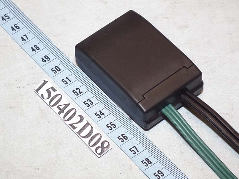
YLI-HSNHI2
May 17, 2015iTwinkle Wifi Module
Equipment Class
DTS - Digital Transmission System
YLIGT-FTXL1
Apr 28, 2015433MHz RF Controller
Equipment Class
DSC - Part 15 Security/Remote Control Transmitter
YLI720002011B
Jun 21, 2011Color Effects Remote Control
Equipment Class
DSC - Part 15 Security/Remote Control Transmitter