YLI720002010AColor Effects Remote Control
H.S. CRAFT MANUFACTURING CO.
Click to zoom
Application Details
- Equipment Class
- DSC - Part 15 Security/Remote Control Transmitter
- Date of Grant
- Aug 18, 2010
- Application Purpose
- Original Equipment
- Date of Application
- Aug 18, 2010
- Equipment Note
- Color Effects Remote Control
- Frequency Range
- 433.92000000 - 433.92000000
- Company
- H.S. CRAFT MANUFACTURING CO.
- Country
- Taiwan
Documents & Files
Document Text
Text extracted from the exhibit documents filed with the FCC. Open a document above to read the original.
Users Manual
USE AND CARE INSTRUCTIONS • When the product is placed on a live tree, the tr ee should be well maintained and fresh. Do not place on live trees in which the needles are brown or break off easily. Keep the tree holder filled with water. • If the product is placed on a tree, the tree shou ld be well secured and stable. • Before using, or reusing, inspect product careful ly. Discard any products that have cut, damaged or frayed wire insulation o r cords, cracks in the lampholders or enclosures, loose connections, or e xposed copper wire. • When storing the product, carefully remove the prod uct from wherever it is placed, including trees, branches, or bushes, to avoid any undue strain or stress on the product conductors, connect ions and wires. • When not in use, store neatly in a cool, dry loca tion protected from sunlight. Install Class 2 Power Supply To String: NOTE: Use only this GE branded, Class 2 Power Supply, Model SA3A-050-3000, manufactured by TDC that was provide d with this product. DO NOT use this adapter with any other product. 1. Remove the Power Supply from its packing box. 2. The LED string is fitted with a 2-pronged fittin g. 3. Align the notch in fitting with the inner tab on end of Power Supply {Fig. 1} 4. Fully insert the fitting into the Power Supply {Fig. 2} 5. Screw the collar completely onto the Power Suppl y turning clockwise {Fig. 3 } Operate the Remote : 1. Remove the remote from its packing box. Note: The batteries were pre-installed at the factory. 2. Pull out the plastic film from the battery cover to energize the remote. {Fig. 1} 3. The remote has two buttons {Fig. 2}: a. O N / O F F – Press to turn the set OFF; press again to turn th e set ON. b. F u n c t i o n – Press to change the light pattern to the next mo de. NOTES: 1. Fully inserting the plug on the Class 2 Power Su pply into a working outlet energizes the string. 2. When using the remote to turn ON your set there may be up to a 2 second delay before the light pattern starts working. 3. To change light patterns it is recommended to wa it 2 seconds each time after pressing the Function button until you reach the desired p attern. 4. If for any reason the signal from the remote (tr ansmitter) to the control box (receiver) hangs up, please turn off and then restart the po wer to the set. 5. If a power interruption, the system’s memory kee ps the last light pattern displayed. 6 . The maximum effective operating distance of the rem ote is 33 ′ (10m) Setting Same Light Pattern On Multiple Sets Before installing your sets you will need to preset each string to the same light pattern. 1. Plug one set into a working 120V outlet. 2. Using any remote press the Function button until you have selected the desired lighting effect and note that pattern from the re mote. 3. Unplug the set and then plug in the next set int o the same outlet for ease of controlling. 4. With the remote follow Steps 2 and 3 setting the same light pattern (same function ) as the previous set. 5. When the strings are all set to the same functio n, power up all sets using multiple outlets. They will all light displaying the same pattern as the control module contains a built-in memory function. Once plugged in each set will start through their pattern. 6.To have all sets start together, press OFF on you r remote and now press ON. 7. Install your sets. Follow step 6 to get all your sets operating on the same light pattern. Notes: 1. With all sets lighted, pressing the Function but ton will change all sets to the same (next) pattern. 2. These are Radio Frequency controlled devices. AL L sets within the effective range will be affected and controlled using any one remot e. 3. To have different lighting patterns, in Step 2 s et each string to a different function. 4. To group sets together to their own function fol low the above setting one group to its same function and then the second to their same y et different function. 5. If used with a mechanical/digital timer, only on e timer must control all sets. In this case, do not turn sets off using the remote or se ts will not turn on with timer. Fig. 2 Fig. 3 Fig.1 Fig. 1 Fig. 2 6. Setting the same light pattern works ONLY with ligh ts sets having the same number of LEDs. 7. Due to component tolerances there will be cycle time differences between sets. BATTERY CAUTION: • Always purchase the correct size and grade of batte ry most suitable for the intended use. • Replace all batteries of a set at the same time. • Clean the battery contacts and also those of the device prior to battery installation. • Ensure the batteries are installed correctly with regard to polarity (+ and -). • Remove batteries from equipment which is not to b e used for an extended period of time. •Remove used batteries promptly. NOTE: LEDs in this set are non-replaceable. Tampering wit h this set will void the warranty. This device complies with Part 15 of the FCC Rules. Operation is subject to the following two condition s: F this device may not cause harmful interference, a nd F this device must accept any interference received , including interference that may cause undesired operation. Modifications not approved by the party responsible for compliance could void user’s authority to operate the equipment. NOTE: This equipment has been tested and found to comply with the limits for Class B digital device, pursuant to Part 15 of the FCC Ru les. These limits are designed to provide reasonable protection against harmful inter ference in a residential installation. This equipment generates, uses and can radiate radi o frequency energy and, if not installed and used in accordance with the instructi ons, may cause harmful interference to radio or television reception, which can be dete rmined by turning the equipment off and on, the user is encouraged to try to correct th e interference by one or more of the following measures: * Reorient or relocate the receiving antenna. * Increase the separation between the equipment and t …
Text truncated - open the document above for the full version.
External Photos
Page: 1
Internal Photos
Page: 2 Page: 3 Page: 4 Page: 5 Page: 6
Operational Description
FCC ID: YLI720002010A Report No.: RF990419D13A Operational Description The transmitter of the EUT (Color Effects Remote Control) is powered by 3Vdc from batteries. The type of antenna is Printed Antenna. The output power of this device is very low. Under normal use condition, the transmitter and the receiver are quite close, so high EIRP power is neither necessary nor allowed because of interference.
Test Report
Report No.: RF990419D13A 1 Report Format Version 3.0.1 Reference No.: 990803D07 FCC TEST REPORT REPORT NO.: RF990419D13A MODEL NO.: 720002010A FCC ID: YLI720002010A RECEIVED: Aug. 3, 2010 TESTED: Aug. 5 ~ 9, 2010 ISSUED: Aug. 16, 2010 APPLICANT: H.S. CRAFT MANUFACTURING CO. ADDRESS: 10F, NO. 35, GUANG FU N. ROAD, TAIPEI, TAIWAN ISSUED BY: Bureau Veritas Consumer Products Services (H.K.) Ltd., Taoyuan Branch LAB LOCATION: No. 47, 14th Ling, Chia Pau Tsuen, Lin Kou Hsiang, Taipei Hsien 244, Taiwan This test report consists of 25 pages in total. It may be duplicated completely for legal use with the approval of the applicant. It should not be reproduced except in full, without the written approval of our laboratory. The client should not use it to claim product endorsement by TAF or any government agencies. The test results in the report only apply to the tested sample. Report No.: RF990419D13A 2 Report Format Version 3.0.1 Reference No.: 990803D07 Table of Contents 1. CERTIFICATION..........................................................................................3 2. SUMMARY OF TEST RESULTS..................................................................4 2.1 MEASUREMENT UNCERTAINTY...............................................................4 3. GENERAL INFORMATION..........................................................................5 3.1 GENERAL DESCRIPTION OF EUT............................................................5 3.2 DESCRIPTION OF TEST MODES..............................................................6 3.2.1 CONFIGURATION OF SYSTEM UNDER TEST.........................................6 3.2.2 TEST MODE APPLICABILITY AND TESTED CHANNEL DETAIL..............7 3.3 GENERAL DESCRIPTION OF APPLIED STANDARDS.............................9 3.4 DESCRIPTION OF SUPPORT UNITS........................................................9 4. TEST TYPES AND RESULTS....................................................................10 4.1 CONDUCTED EMISSION MEASUREMENT............................................10 4.2 RADIATED EMISSION MEASUREMENT.................................................10 4.2.1 LIMITS OF RADIATED EMISSION MEASUREMENT...............................10 4.2.2 TEST INSTRUMENTS..............................................................................12 4.2.3 TEST PROCEDURES...............................................................................13 4.2.4 DEVIATION FROM TEST STANDARD.....................................................13 4.2.5 TEST SETUP ...........................................................................................14 4.2.6 EUT OPERATING CONDITIONS..............................................................14 4.2.7 TEST RESULTS........................................................................................15 4.3 20dB OCCUPIED BANDWIDTH MEASUREMENT...................................18 4.3.1 LIMITS OF EMISSION BANDWIDTH MEASUREMENT...........................18 4.3.2 TEST INSTRUMENTS..............................................................................18 4.3.3 TEST PROCEDURE.................................................................................18 4.3.4 DEVIATION FROM TEST STANDARD.....................................................19 4.3.5 TEST SETUP ...........................................................................................19 4.3.6 TEST RESULTS........................................................................................20 4.4 DEACTIVATION TIME...............................................................................21 4.4.1 LIMITS OF DEACTIVATION TIME MEASUREMENT................................21 4.4.2 TEST INSTRUMENTS..............................................................................21 4.4.3 TEST PROCEDURES...............................................................................21 4.4.4 DEVIATION FROM TEST STANDARD.....................................................21 4.4.5 TEST SETUP ...........................................................................................21 4.4.6 TESE RESULTS........................................................................................22 5. PHOTOGRAPHS OF THE TEST CONFIGURATION.................................23 6. INFORMATION ON THE TESTING LABORATORIES...............................24 7. APPENDIX A – MODIFICATIONS RECORDERS FOR ENGINEERING CHANGES TO THE EUT BY THE LAB......................................................25 Report No.: RF990419D13A 3 Report Format Version 3.0.1 Reference No.: 990803D07 1. CERTIFICATION PRODUCT: Color Effects Remote Control BRAND NAME: GE MODEL NO.: 720002010A APPLICANT: H.S. CRAFT MANUFACTURING CO. TESTED: Aug. 5 ~ 9, 2010 TEST SAMPLE: ENGINEERING SAMPLE STANDARDS: FCC Part 15, Subpart C (Section 15.231) ANSI C63.4-2003 The above equipment has been tested by Bureau Veritas Consumer Products Services (H.K.) Ltd., Taoyuan Branch, and found compliance with the requirement of the above standards. The test record, data evaluation & Equipment Under Test (EUT) configurations represented herein are true and accurate accounts of the measurements of the sample’s EMC characteristics under the conditions specified in this report. PREPARED BY : , DATE: Aug. 16, 2010 ( Jessica Cheng / Specialist ) TECHNICAL ACCEPTANCE : , DATE: Aug. 16, 2010 Responsible for RF ( Jamison Chan / Supervisor ) APPROVED BY : , DATE: Aug. 16, 2010 ( Ken Liu / Manager) Report No.: RF990419D13A 4 Report Format Version 3.0.1 Reference No.: 990803D07 2. SUMMARY OF TEST RESULTS The EUT has been tested according to the following specifications: APPLIED STANDARD: FCC Part 15, Subpart C (Section 15.231) STANDARD SECTION TEST TYPE AND LIMIT RESULT REMARK 15.207 Conducted Emission Test N/A Power supply is 3Vdc from batteries 15.209 15.231(b) Radiated Emission Test PASS Minimum passing margin is –1.3dB at 2603.52MHz 15.231(c) Emission Bandwidth Measurement PASS Meet the requirement of limit 15.231(a) De-activation PASS …
Text truncated - open the document above for the full version.
Test Setup Photos
1 PHOTOGRAPHS OF THE TEST CONFIGURATION RADIATED EMISSION TEST
Contact Information
Applicant
SARAH LU(SALES COORDINATOR)
Technical Contact
Bureau Veritas CPS (H.K.) Ltd. Taoyuan BranchKen Liu
[email protected]886-2-2605-2180
No. 47, 14 Ling, Chia Pau Tsuen, Lin Kou Hsiang, · Linkou, Taipei · Taiwan
Non-Technical Contact
Bureau Veritas CPS (H.K.) Ltd. Taoyuan BranchWendy Liao
[email protected]886-3-3183232
Test Firm
Bureau Veritas CPS (H.K.) Ltd. Taoyuan BranchRichard Chen
Technical Specifications
| # | Rule Parts | Frequency Range | Power Output |
|---|---|---|---|
| 1 | 15.231 | 433.92 MHz - 433.92 MHz | - |
Other Applications from H.S. CRAFT MANUFACTURING CO.

YLIHC-TX40
Jan 02, 2023Remote control
Equipment Class
DXX - Part 15 Low Power Communication Device Transmitter
YLIHC-TX20
Apr 08, 2020HC-TX20 remote control
Equipment Class
DSC - Part 15 Security/Remote Control Transmitter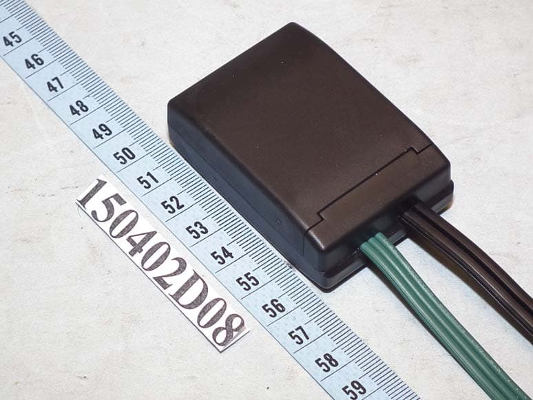
YLI-HSNHI2
May 17, 2015iTwinkle Wifi Module
Equipment Class
DTS - Digital Transmission System
YLIGT-FTXL1
Apr 28, 2015433MHz RF Controller
Equipment Class
DSC - Part 15 Security/Remote Control Transmitter
YLINHI-610
Mar 24, 2013iTwinkle Bluetooth Module
Equipment Class
DSS - Part 15 Spread Spectrum Transmitter