YVAPH100WRWireless Repeater
Green Badge LLC d/b/a UgMO Technologies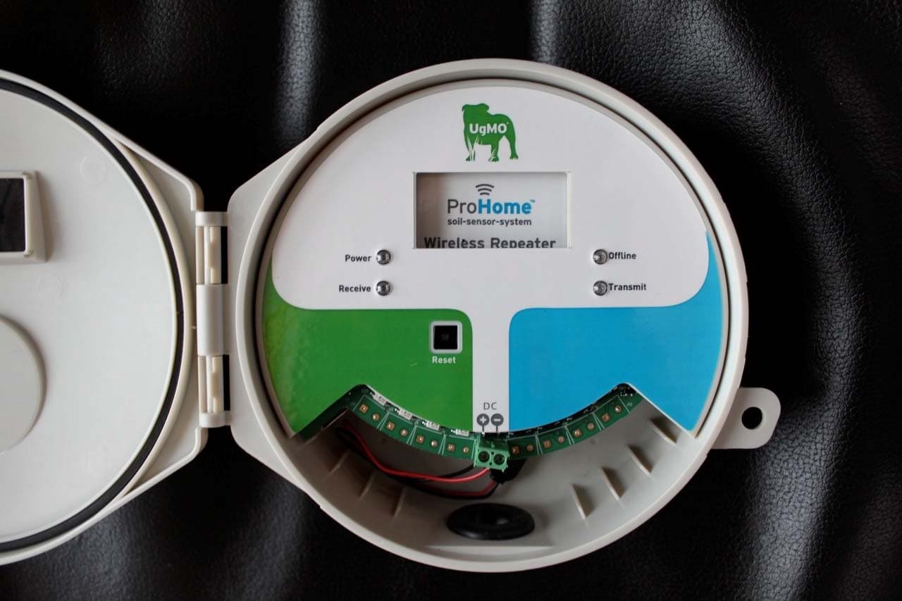
Click to zoom
Application Details
- Equipment Class
- DSR - Part 15 Remote Control/Security Device Transceiver
- Date of Grant
- Mar 06, 2011
- Application Purpose
- Original Equipment
- Date of Application
- Mar 06, 2011
- Equipment Note
- Wireless Repeater
- Frequency Range
- 434.00000000 - 434.00000000
- Country
- United States
Documents & Files
Document Text
Text extracted from the exhibit documents filed with the FCC. Open a document above to read the original.
Users Manual
Installation Manual WIRELESS REPEATER PH100WR UgMO Technoogies • 840 First, Suite 300 • King of Prussia, PA 19406 • www.UgMO.com The UgMo ProHome Wireless Soil-Sensor-System has been designed to deliver wireless range up to 600 feet from the base station to its sensors. However, there will be situations when a base station cannot establish a connection with a sensor within that distance. This can be caused by many factors that may not be within the control of the installer. There may be other times when additional range is required due to the size of a property. The UgMO ProHome PH100WR Repeater has been developed to provide both improved and extended range between UgMO PH100WS Soil Sensors and UgMO PH100BS Base Stations. . The PH100WR Repeater is compatible with all generations of UgMO Sensors and Base Stations. No pairing, programing or other set-up is required. Just posi- tion the Repeater and simply plug in the provided 12V AC/DC transformer. The Repeater will automatically forward any sensor packets it is able to receive. Install a Repeater mid-way between Sensors and Base Stations to enhance range. Repeaters are suitable for mounted both inside or outside provided the AC outlet provides proper protection for the AC/DC transformer from the elements. The AC adaptor can be placed up to 300’ away from the Repeater by splicing suitable wire. For long distances, multiple repeaters may be used to “hop” the signal from the sensors to the base station. Wireless Repeater Installation Manual INTRODUCTION EASY INSTALLATION 1 Power indicator 2 Receive (Blinks when a sensor packet is received) 3 Offline (Repeater will not transmit when lit) 4 Transmit (Blinks when a sensor packet is transmitted) 5 Select Button (Pressing the Select button for 3 seconds stops the repeater from transmitting) 6 DC Terminals (Terminals for attaching wires from AC/DC Transformer Components FROM CLOCK ZONESZONES TO VALVES UgMO Con fidential The Network Controller User Interface. On po wer-up , you ’ll see the f ollowing sc ree n. Th is t imes out aft er 10 second s, or press t he Select Butt on t o move on. 1 2 3 4 5 6 Th e major section s: Th is catch-all view of the top sc ree n sho ws the va riety of information you may see . Th ere are 6 columns rep resen ting the 6 Zone s controlled by the Network Controller. At the top of ea ch column is a de sc ription of the zo ne contr ol: . At the ve ry top, left corne r, the Network controller ind icates whe the r it is in ‘Automatic’ mode – whe re Sen sors control watering , or ‘Byp ass ’ mode , whe re watering is alway s allowed. At the top righ t i s a calculation of ave rage water sav ing s: 4 3 6 5 2 1 SELECT POWER RECEIVE OFFLINE TRANSMIT Wireless Repeater DC Placement of a Repeater The optimal location of a repeater is half-way between the base station and the hard-to-see sensor (Sensor 2) at least 5 feet above the ground. The repeater may be placed inside the building if a suitable location can be found. It is OK to locate it within a closet provided AC power is available. (Option 1) Alternatively, the repeater may be positioned outside in a location with few obstructions between it and the sensor and base station. (Option 2) Up to 300 ft of low voltage buriable wire may be spliced onto the transformer wire to extend placement if the AC outlet is not conveniently located at this position. Should Option 1 or 2 not be available, a location on the outside of the building near an AC outlet may be used. (Option 3) Placement may require some trial and error until a reliable signal is established between the sensor and the base station. Sensor 1 Base Station Wall Option 1 Option 2 Option 3 Placement of a Repeater The optimal location of a repeater is half-way between the base station and the hard-to-see sensor (Sensor 2) at least 5 feet above the ground. The repeater may be placed inside the building if a suitable location can be found. It is OK to locate it within a closet provided AC power is available. (Option 1) Alternatively, the repeater may be positioned outside in a location with few obstructions between it and the sensor and base station. (Option 2) Up to 300 ft of low voltage buriable wire may be spliced onto the transformer wire to extend placement if an AC outlet is not conveniently located at this position. Should Option 1 or 2 not be available, a location on the outside of the building near an AC outlet may be used. (Option 3) Placement may require some trial and error until a reliable signal is established between the sensor and the base station. Hard-to-see sensor Sensor 2 Sensor 3 Checking signal strength The top screen to the right is accessible on the ProHome Base Station. (See page 27 -28 of the user manual) Q-Value: This number represents the percent of the expected transmissions received from a sensor over the past four days or since the Base Station was last restarted - whichever is shorter. This value is “0” until the first 90 minute interval has passed. If the Q-Value, is below 40%, a Repeater may be advisable. In this example, the Q-Value is 23%. Short-Term Signal Quality Indicator: At the bottom of the screen, a series of dashes and/or boxes will appear when a sensor has been paired to the Base Station. This indicator displays the number of transmissions it has received from the sensor over the past 60 minutes. The indicator draws a box on the right while waiting for a transmission. Each time an expected transmission is received a solid box is drawn to the left. If a transmission is not received with the expected time period, an empty box is drawn. Repeater Properly Installed: The same view sensor screen for the hard-to-see sensor should look similar to the bottom screen to the right when the repeater is properly installed. The short-term indicator shows solid boxes and the Q-Value should be above 60%. (Remember that the Q-Value takes 90 minutes to populate) Menu 5 / 6 View Sensors R 10000042 X Z:_______C 2 A01 Q089 T:+076.2F; W:+27.0% R099 Menu …
Text truncated - open the document above for the full version.
ID Label/Location Info
1.6 inch w X 1.4 inch h FCC ID: YVAPH100WR
Test Report
Nemko USA, Inc. 11696 Sorrento Valley Rd., Suite F San Diego, CA 92121-1024 Phone (858) 755-5525 Fax (858) 452-1810 FCC Part 15 Subpart C, 15.231: 07/03/2011 Certification Test Report In Accordance With: FCC Part 15 Subpart C, 15.231 Applicant: Green Badge LLC dba UgMO Technologies 840 1st Ave., Ste. 300 King of Prussia, PA 19406 Equipment Under Test (EUT): Wireless Repeater Model: PH100WR FCC ID: YVAPH100WR. Tested By: Nemko USA Inc. 11696 Sorrento Valley Road, Suite F San Diego, CA 92121 Test Report Number: 2011 10165832 FCC Date: January 13, 2011 Project Number 43834 NEX Number 149167 Total Number of Pages: 27 Nemko USA, Inc. 11696 Sorrento Valley Road, Suite F, San Diego, CA 92121 Phone (858) 755-5525 Fax (858) 452-1810 Report Number: 2011 10165832 FCC FCC ID: YVAPH100WR. Specification: FCC Part 15 Subpart C, 15.231 Page 2 of 27 Section 1. Summary of Test Results 1.1 General All measurements are traceable to national standards These tests were conducted on a sample of the equipment for the purpose of demonstrating compliance with Part 15; Subpart C. Radiated tests were conducted is accordance with ANSI C63.4-2003. Radiated emissions are made on an open area test site. A description of the test facility is on file with the FCC. The assessment summary is as follows: Apparatus Assessed: Wireless Repeater Model: PH100WR Specification: FCC Part 15 Subpart C, 15.231 Date Received in Laboratory: January 12, 2011 Compliance Status: Complies Exclusions: None Non-compliances: None Nemko USA, Inc. 11696 Sorrento Valley Road, Suite F, San Diego, CA 92121 Phone (858) 755-5525 Fax (858) 452-1810 Report Number: 2011 10165832 FCC FCC ID: YVAPH100WR. Specification: FCC Part 15 Subpart C, 15.231 Page 3 of 27 1.2 Report Release History REVISION DATE COMMENTS - January 13, 2010 Prepared By: Alan Laudani - January 13, 2010 Initial Release: Alan Laudani Note that the results contained in this report relate only to the items tested and were obtained in the period between the date of initial receipt of samples and the date of issue of the report. This test report has been completed in accordance with the requirements of ISO/IEC 17025. Nemko USA Inc. authorizes the applicant to reproduce this report provided it is reproduced in its entirety and for use by the company’s employees only. Any use which a third party makes of this report, or any reliance on or decisions to be made based on it, are the responsibility of such third parties. Nemko USA Inc. accepts no responsibility for damages, if any, suffered by any third party as a result of decisions made or actions based on this report. Alan Laudani, RF/EMC Test Engineer Nemko USA, Inc. 11696 Sorrento Valley Road, Suite F, San Diego, CA 92121 Phone (858) 755-5525 Fax (858) 452-1810 Report Number: 2011 10165832 FCC FCC ID: YVAPH100WR. Specification: FCC Part 15 Subpart C, 15.231 Page 4 of 27 TABLE OF CONTENTS Section 1. Summary of Test Results....................................................................... 2 1.1 General................................................................................................................. 2 1.2 Report Release History ........................................................................................ 3 Section 2: Equipment Under Test ................................................................................ 5 2.1 Theory of Operation.............................................................................................. 5 2.2 Technical Specifications of the EUT ..................................................................... 5 Section 3: Test Conditions ........................................................................................... 6 3.1 Specifications ....................................................................................................... 6 3.2 Deviations From Laboratory Test Procedures...................................................... 6 3.3 Test Environment ................................................................................................. 6 3.4 Test Equipment .................................................................................................... 6 Section 4: Observations ............................................................................................... 7 4.1 Modifications Performed During Assessment....................................................... 7 4.2 Record Of Technical Judgements ........................................................................ 7 4.3 EUT Parameters Affecting Compliance ................................................................ 7 4.4 Tests Deleted ....................................................................................................... 7 4.5 Additional Observations........................................................................................ 7 Section 5: Results Summary ........................................................................................ 8 5.1 Test Results.......................................................................................................... 8 Appendix A: Test Results...........................................................................................A1 Conducted Emissions....................................................................................................A1 Occupied Bandwidth.....................................................................................................A2 Frequency Stability........................................................................................................A4 Types of Momentary Signals .........................................................................................A5 Field strength of fundamental ........................................................................................A9 Spurious Emissions.......................................................................................................A9 Conducted Emissions Test Data—Receive Mode…
Text truncated - open the document above for the full version.
Contact Information
Applicant
Kathy Sohrabi(Vice President of Engineering)
Technical Contact
Green Badge LLC d/b/a/ UgMO TechnologiesKathy Sohrabi
[email protected](484) 524-3468
840 First Avenue, suite 300 · King of Prussia, Pennsylvania · United States
Non-Technical Contact
Green Badge LLC d/b/a/ UgMO TechnologiesKathy Sohrabi
[email protected](484) 524-3468
Test Firm
Nemko USA, Inc. - San Diego EMC DivisionJan Blomgren
[email protected]760-444-3500
Technical Specifications
| # | Rule Parts | Frequency Range | Power Output |
|---|---|---|---|
| 1 | 15.231,15.231(e) | 434 MHz - 434 MHz | - |
Other Applications from Green Badge LLC d/b/a UgMO Technologies
YVAUG400S
Dec 19, 2013Wireless Ground Sensor
Equipment Class
DSC - Part 15 Security/Remote Control Transmitter
YVAUG1000BA
Jul 18, 2013902-928 MHz ISM BAND BRIDGE
Equipment Class
DSS - Part 15 Spread Spectrum Transmitter
YVAUG1000RA
Jul 18, 2013902-928 MHz ISM BAND REPEATER
Equipment Class
DSS - Part 15 Spread Spectrum Transmitter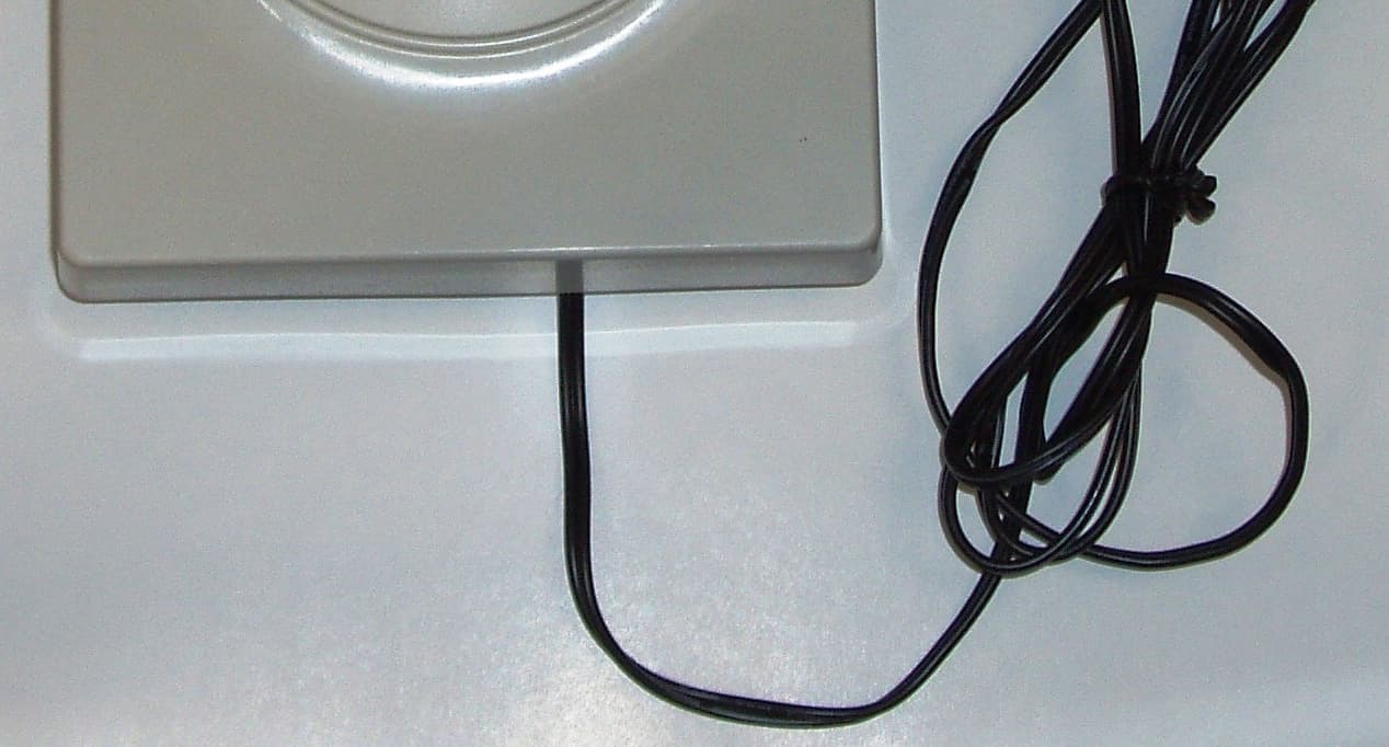
YVAUG1000R
Sep 16, 2012902 - 928 MHz ISM BAND REPEATER
Equipment Class
DSS - Part 15 Spread Spectrum Transmitter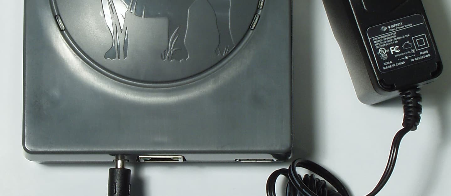
YVAUG1000B
Sep 10, 2012902 - 928 MHZ ISM BAND BRIDGE
Equipment Class
DSS - Part 15 Spread Spectrum Transmitter