YVAPH100WSWireless Ground Sensor
Green Badge LLC d/b/a UgMO Technologies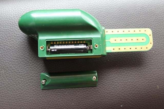
Click to zoom
Application Details
- Equipment Class
- DSC - Part 15 Security/Remote Control Transmitter
- Date of Grant
- Jan 16, 2011
- Application Purpose
- Original Equipment
- Date of Application
- Jan 13, 2011
- Equipment Note
- Wireless Ground Sensor
- Frequency Range
- 434.00000000 - 434.00000000
- Country
- United States
Documents & Files
Document Text
Text extracted from the exhibit documents filed with the FCC. Open a document above to read the original.
Users Manual
Installation and User Manual UgMO Technologies• 840 First, Suite 300 • King of Prussia, PA 19406 • www.UgMO.com Please leave with property owner Installation and User Manual UgMO™ monitors soil moisture in the root zones of your plants, limiting watering by your irrigation controller to avoid over-watering. UgMO consists of two components, the UgMO Wireless Sensor and the UgMO Base Station. Up to 24 wireless sensors can be paired, assigned and buried to control up to 6 watering zones (valves). The Base Station is wired between any common elec- tronic irrigation controller (sometimes called a ‘clock’), and the valves controlling watering in up to six zones. UgMO supports the control of a Master Valve or Pump via a special output. UgMO saves water and improves plant health by limiting overwatering for lawns and ornamental plantings. Irrigation controllers can be set according to the hottest or driest conditions expected. UgMO limits watering to be ‘just enough’. UgMO wireless sensors have a patented electronic moisture sensing circuit and low power radio signal. Two uniquely configured batteries (supplied and installed) provide an operating life of up to 5 years. The UgMO Base Station is powered by your Irrigation controller. Installation requires only basic electrical tools (a wire stripper, crimper, connectors) a thin flat screwdriver, drywall screws, a Philip head screwdriver for mounting and an AC voltmeter (Digital MultiMeter). UgMO devices are weather resistant for outdoor use. Wireless Sensors are buried at depths from 1” to 4” according to plant and soil types and operate at distances up to 600 feet, depending on soil type, depth, and line of site to the Base Station. UgMO is easy to in- stall, effective and long lasting. It is not uncommon for a typical home to reduce water use by as much as 45%. Table of Contents Components .....................................................................................................................................................2 Preparing to Install ..........................................................................................................................................4 Site Assessment ...............................................................................................................................................5 Installing the Base Station ..............................................................................................................................6 Mounting the Base Station ....................................................................................................................6 Wiring a Single Base Station .................................................................................................................7 Determining AC Polarity of Existing Irrigation Clock ........................................................................10 Wiring 2 Base Stations with a Pump/Master Valve to Control Up to 12 Stations .............................11 Base Station User Interface...........................................................................................................................14 Main Screen .........................................................................................................................................14 Auto/Bypass Indicator .................................................................................................................15 Pump/Master Valve Indicator .....................................................................................................15 Water Savings Indicator ..............................................................................................................15 Zone Control Indicator ................................................................................................................15 Zone Moisture Level Indicator ....................................................................................................16 Battery and Wireless Strength Indicator ....................................................................................17 Set Contrast .........................................................................................................................................17 Manage Sensors ..................................................................................................................................18 Pairing sensors to Base Station: Choosing Sensors ..................................................................18 Assigning a Common Sensor .....................................................................................................20 INSTALLATION AND USER MANUAL Assigning More than one Sensor to a Zone ................................................................................21 Assigning a Sensor to More Than One Zone ..............................................................................21 Pairing Sensors to Base Station: Manual Entry .........................................................................22 Setting Moisture Levels .......................................................................................................................23 Manage System Settings .....................................................................................................................23 Setting Auto and Bypass .............................................................................................................23 Setting Global Cold Temperature Override ................................................................................24 Manage Zone Settings .........................................................................................................................25 Zone Bypass Setting ...................................................................................................................25 Multiple Sensors Per Zone Settings ..........................................................…
Text truncated - open the document above for the full version.
ID Label/Location Info
FCC ID: YVAPH100WS PH100WSThis device complies with Part 15 of the FCC Rules. Operation is subject to the following two conditions: (1) This device may not cause harmful interference, and (2) This device must accept any interference received, including interference that may cause undesired operation. 1 inch width x 0.5 inch height
Test Report
Nemko USA, Inc. 11696 Sorrento Valley Rd., Suite F San Diego, CA 92121-1024 Phone (858) 755-5525 Fax (858) 452-1810 FCC Part 15 Subpart C, 15.231: 13/01/2011 Certification Test Report In Accordance With: FCC Part 15 Subpart C, 15.231& 15.231(e) Applicant: Green Badge LLC dba UgMO Technologies 840 1st Ave., Ste. 300 King of Prussia, PA 19406 Equipment Under Test (EUT): Wireless Soil Sensor Model: PH100WS FCC ID: YVAPH100WS Tested By: Nemko USA Inc. 11696 Sorrento Valley Road, Suite F San Diego, CA 92121 Test Report Number: 2010 09149167 FCC Date: January 13, 2011 Project Number 43834 NEX Number 149167 Total Number of Pages: 30 Nemko USA, Inc. 11696 Sorrento Valley Road, Suite F, San Diego, CA 92121 Phone (858) 755-5525 Fax (858) 452-1810 Report Number: 2010 09149167 FCC FCC ID: YVAPH100WS Specification: FCC Part 15 Subpart C, 15.231 Page 2 of 30 Section 1. Summary of Test Results 1.1 General All measurements are traceable to national standards These tests were conducted on a sample of the equipment for the purpose of demonstrating compliance with Part 15; Subpart C. Radiated tests were conducted is accordance with ANSI C63.4-2003. Radiated emissions are made on an open area test site. A description of the test facility is on file with the FCC. The assessment summary is as follows: Apparatus Assessed: Wireless Soil Sensor Model: PH100WS Specification: FCC Part 15 Subpart C, 15.231 Date Received in Laboratory: May 13, 2010 Compliance Status: Complies Exclusions: None Non-compliances: None Nemko USA, Inc. 11696 Sorrento Valley Road, Suite F, San Diego, CA 92121 Phone (858) 755-5525 Fax (858) 452-1810 Report Number: 2010 09149167 FCC FCC ID: YVAPH100WS Specification: FCC Part 15 Subpart C, 15.231 Page 3 of 30 1.2 Report Release History REVISION DATE COMMENTS - January 13, 2010 Prepared By: Alan Laudani - January 13, 2010 Initial Release: Alan Laudani Note that the results contained in this report relate only to the items tested and were obtained in the period between the date of initial receipt of samples and the date of issue of the report. This test report has been completed in accordance with the requirements of ISO/IEC 17025. Nemko USA Inc. authorizes the applicant to reproduce this report provided it is reproduced in its entirety and for use by the company’s employees only. Any use which a third party makes of this report, or any reliance on or decisions to be made based on it, are the responsibility of such third parties. Nemko USA Inc. accepts no responsibility for damages, if any, suffered by any third party as a result of decisions made or actions based on this report. Alan Laudani, RF/EMC Test Engineer Nemko USA, Inc. 11696 Sorrento Valley Road, Suite F, San Diego, CA 92121 Phone (858) 755-5525 Fax (858) 452-1810 Report Number: 2010 09149167 FCC FCC ID: YVAPH100WS Specification: FCC Part 15 Subpart C, 15.231 Page 4 of 30 TABLE OF CONTENTS Section 1. Summary of Test Results....................................................................... 2 1.1 General................................................................................................................. 2 1.2 Report Release History ........................................................................................ 3 Section 2: Equipment Under Test ................................................................................ 5 2.1 Theory of Operation.............................................................................................. 5 2.2 Technical Specifications of the EUT ..................................................................... 5 Section 3: Test Conditions ........................................................................................... 6 3.1 Specifications ....................................................................................................... 6 3.2 Deviations From Laboratory Test Procedures...................................................... 6 3.3 Test Environment ................................................................................................. 6 3.4 Test Equipment .................................................................................................... 6 Section 4: Observations ............................................................................................... 7 4.1 Modifications Performed During Assessment....................................................... 7 4.2 Record Of Technical Judgements ........................................................................ 7 4.3 EUT Parameters Affecting Compliance ................................................................ 7 4.4 Tests Deleted ....................................................................................................... 7 4.5 Additional Observations........................................................................................ 7 Section 5: Results Summary ........................................................................................ 8 5.1 Test Results.......................................................................................................... 8 Appendix A: Test Results...........................................................................................A1 Conducted Emissions....................................................................................................A1 Occupied Bandwidth.....................................................................................................A2 Frequency Stability........................................................................................................A4 Types of Momentary Signals .........................................................................................A5 Radiated Emissions.......................................................................................................A9 Spurious Emissions.....................................................................................................A12 Conducted Emissions Test Data—R…
Text truncated - open the document above for the full version.
Contact Information
Applicant
Kathy Sohrabi(Vice President of Engineering)
Technical Contact
Green Badge LLC d/b/a/ UgMO TechnologiesKathy Sohrabi
[email protected](484) 524-3468
840 First Avenue, suite 300 · King of Prussia, Pennsylvania · United States
Non-Technical Contact
Green Badge LLC d/b/a/ UgMO TechnologiesKathy Sohrabi
[email protected](484) 524-3468
Test Firm
Nemko USA, Inc. - San Diego EMC DivisionJan Blomgren
[email protected]760-444-3500
Technical Specifications
| # | Rule Parts | Frequency Range | Power Output |
|---|---|---|---|
| 1 | 15.231,15.231(e) | 434 MHz - 434 MHz | - |
Other Applications from Green Badge LLC d/b/a UgMO Technologies
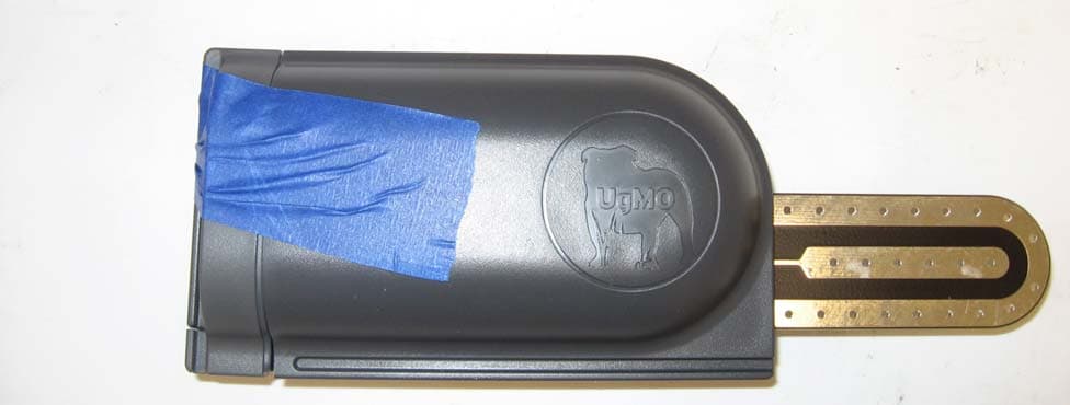
YVAUG400S
Dec 19, 2013Wireless Ground Sensor
Equipment Class
DSC - Part 15 Security/Remote Control Transmitter
YVAUG1000BA
Jul 18, 2013902-928 MHz ISM BAND BRIDGE
Equipment Class
DSS - Part 15 Spread Spectrum Transmitter
YVAUG1000RA
Jul 18, 2013902-928 MHz ISM BAND REPEATER
Equipment Class
DSS - Part 15 Spread Spectrum Transmitter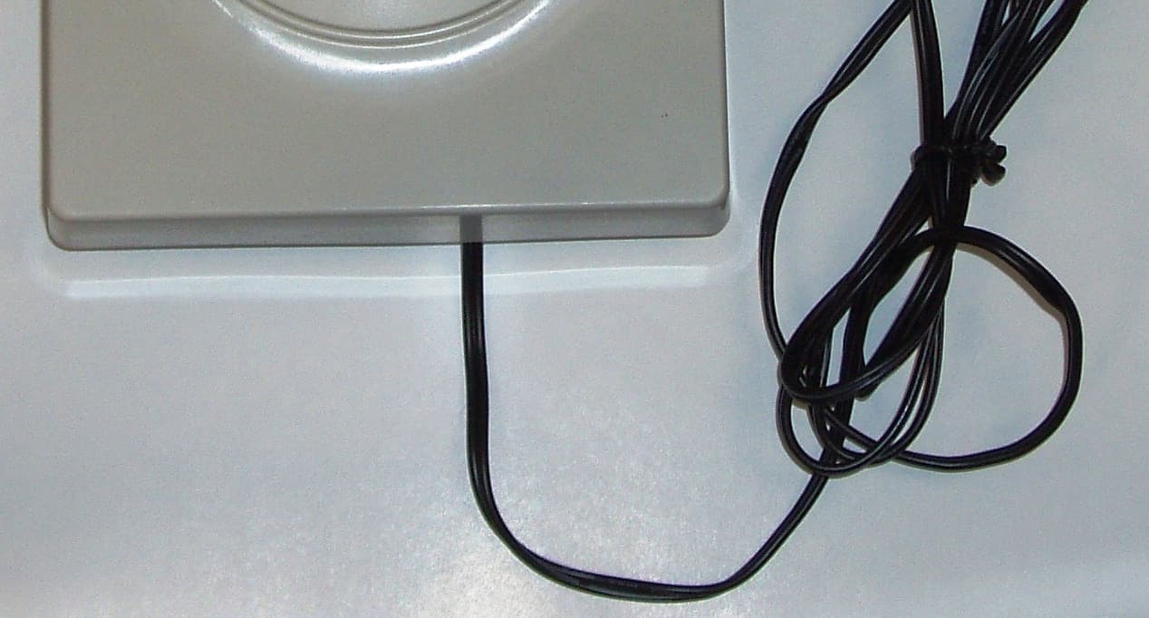
YVAUG1000R
Sep 16, 2012902 - 928 MHz ISM BAND REPEATER
Equipment Class
DSS - Part 15 Spread Spectrum Transmitter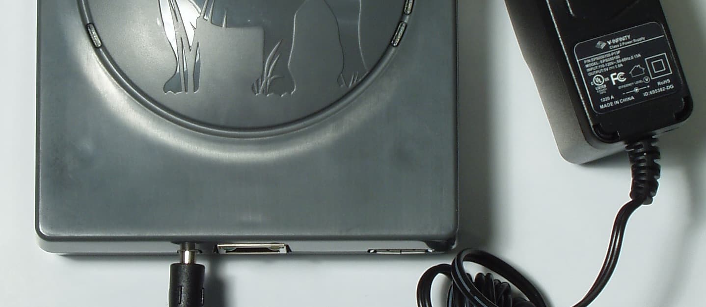
YVAUG1000B
Sep 10, 2012902 - 928 MHZ ISM BAND BRIDGE
Equipment Class
DSS - Part 15 Spread Spectrum Transmitter