YXG-ES800UTUniversal transmitter
Essence Security International ltd.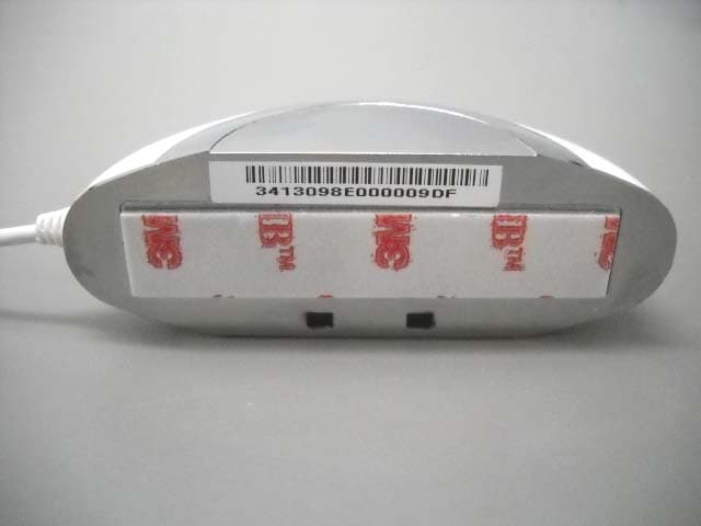
Click to zoom
Application Details
- Equipment Class
- DTS - Digital Transmission System
- Date of Grant
- Mar 09, 2014
- Application Purpose
- Original Equipment
- Date of Application
- Mar 05, 2014
- Equipment Note
- Universal transmitter
- Frequency Range
- 2425.00000000 - 2425.00000000
- Country
- Israel
Documents & Files
Document Text
Text extracted from the exhibit documents filed with the FCC. Open a document above to read the original.
Users Manual
We.R ™ System User Guide ESUG05022 Version 3.3 December 2013 Legal Notice Usage of this document, and all information (including product information) provided within, are subject to the following terms and conditions, and all applicable laws. If you do not agree with these terms, please do not access or use the remainder of this document. This document contains highly confidential information, which is proprietary to Essence Security International (E.S.I.) Ltd. and/or its affiliates (hereafter, "Essence"). No part of this document's contents may be used, copied, disclosed or conveyed to any third party in any manner whatsoever without prior written permission from Essence. The information included in this document is intended for your knowledge and for negotiation purposes only. Essence makes no implicit representations or warranties with respect to such information. The information included in this document is subject to change without notice. Any decision to rely on the information contained herein shall be at your sole responsibility, and Essence will not accept any liability for your decision to use any information or for any damages resulting therefrom. Certain laws do not allow limitations on implied warranties or the exclusion or limitation of certain damages. If these laws apply to you, some or all of the above disclaimers, exclusions, or limitations may not apply to you. By using the information contained herein, you agree that the laws of the state of Israel, without regard to principles of conflict of laws, will govern any dispute of any sort that might arise between you and Essence regarding the information contained herein, and any such dispute shall be settled exclusively in the competent courts of Tel Aviv-Jaffa, Israel. All registered or unregistered trademarks, product names, logos and other service marks mentioned within this document are the property of Essence, or their respective owners. Nothing contained herein shall be construed as conferring by implication, estoppels, or otherwise any license or right, either express or implied, under any patent or trademark of Essence or any third party. No use of any trademark may be made without the prior written authorization of Essence. This document and all of its contents are protected intellectual property of Essence. Any copying, reprinting, reuse, reproduction, adaptation, distribution or translation without the prior written permission of Essence is prohibited. Please check your End User License Agreement (EULA) for terms and Conditions. © 2012 All rights reserved to Essence Security International (E.S.I.) Ltd. Certification Notice NOTE: This equipment has been tested and found to comply with the limits for a Class B digital device, pursuant to part 15 of the FCC Rules. These limits are designed to provide reasonable protection against harmful interference in a residential installation. This equipment generates uses and can radiate radio frequency energy and, if not installed and used in accordance with the instructions, may cause harmful interference to radio communications. However, there is no guarantee that interference will not occur in a particular installation. If this equipment does cause harmful interference to radio or television reception, which can be determined by turning the equipment off and on, the user is encouraged to try to correct the interference by one or more of the following measures: - Reorient or relocate the receiving antenna. - Increase the separation between the equipment and receiver. - Connect the equipment into an outlet on a circuit different from that to which the receiver is connected. - Consult the dealer or an experienced radio/TV technician for help. Changes or modifications to this equipment not expressly approved by the party responsible for compliance (Essence Security International (E.S.I.) Ltd.) could void the user’s authority to operate the equipment. WARNING! To comply with FCC and IC RF exposure compliance requirements, the device should be located at a distance of at least 20 cm from all persons during normal operation. The antennas used for this product must not be co-located or operated in conjunction with any other antenna or transmitter. Le dispositif doit être placé à une distance d'au moins 20 cm à partir de toutes les personnes au cours de son fonctionnement normal. Les antennes utilisées pour ce produit ne doivent pas être situés ou exploités conjointement avec une autre antenne ou transmetteur. For more information, please contact: Essence Security International (E.S.I.) Ltd. 12 Abba Eban Avenue, Ackerstein Towers Bldg. D Herzliya Pituach, 4612001 Israel www.essence-grp.com Tel: +972-73-2447777 Fax: +972-9-7729962 This device complies with FCC Rules Part 15 and with Industry Canada license-exempt RSS standard(s). Operation is subject to the following two conditions: (1) This device may not cause harmful interference, and (2) This device must accept any interference received, including interference that may cause undesired operation Le présent appareil est conforme aux CNR d'Industrie Canada applicables aux appareils radio exempts de licence. L'exploitation est autorisée aux deux conditions suivantes: (1) l'appareil ne doit pas produire de brouillage, et (2) l'utilisateur de l'appareil doit accepter tout brouillage radioélectrique subi, même si le brouillage est susceptible d'en compromettre le fonctionnement. How to Use this Guide We.R ™ System User Guide 3 How to Use this Guide The backbone of this guide is the We.R ™ installation procedure – following an introduction to the system concept, the guide takes you through the steps of identifying the system components and their functions, preparations, and installation of the system components (hardware and software) in the recommended sequence ensuring smooth buildup of your We.R ™ system. This is the largest section of this guide and includes basic understanding of the setup and operation of both the components and …
Text truncated - open the document above for the full version.
Users Manual
Installation of the We.R™ System 82 We.R ™ System User Guide 3.5. The Remote Control Unit (KF) – ES800KF The Remote Control Unit (KF) is a bi-directional ultra-compact We.R ™ system control device with advanced functions for security and automation. Figure 51: The Remote Control Unit (KF) 3.5.1. The Remote Control Unit (KF) Function The Remote Control Unit (KF) incorporates the following functions: End-to-End bi-directional Essence proprietary communication protocol. LED visual indication of system status (Armed/Alarm triggered). Serves as personal SOS alarm device (panic button). 5 command keys to perform: Figure 52: The Remote Control Unit’s Command Keys ARM DISARM Day ARM Night ARM SOS (panic) Status Installation of the We.R™ System We.R ™ System User Guide 83 Remote deactivation in case of loss or theft. Powered by a single 3V CR2450 lithium battery. Long operation period (over 24 months). Protection mechanisms against inadvertent activation. Supports automatic over-the-air software upgrade programming and configuration. 3.5.2. Installing and Activating the Remote Control Unit (KF) Prepare the 3V CR2450 lithium (coin) battery for the KF device before adding it to the system. Note: You may also want to refer to paragraph 5.1 below to get acquainted with the process of installing/replacing a battery in the KF. 1. Press any of the KF’s keys for a while to discharge its circuit. 2. Release the cover of the KF battery compartment by inserting a coin into the slot and turning the cover a quarter of a circle (90 o ) counter-clockwise until the two small bumps align (facing each other) as presented in Figure 53 below: Figure 53: Releasing the Remote Control Unit’s Battery Cover Installation of the We.R™ System 84 We.R ™ System User Guide 3. Remove the cover. 4. Activate the Web Application. 5. Click over the Devices tab and then – over the button. 6. A roll-down menu will open where you need to select Add Key Fob. Figure 54: Add Device Roll-down Menu Figure 55: First Steps of Adding a New Device Installation of the We.R™ System We.R ™ System User Guide 85 7. Add Device window will pop-up (see Figure 56 below). 8. Verify that Device Type is Key Fob. Figure 56: Add Device Window – Key Fob 9. Click over the button to open the list of all pre-defined system Users (see paragraph 3.3.6.4 above). Note: The Remote Control Unit is a specific User device therefore; its User need to be defined/added prior to the following described User assignment. 10. Select the specific User this Remote Control Unit (KF) should be assigned by clicking over its name. 11. Click over the button to assign the Remote Control Unit (KF) to its specified User. 12. The assigned User name will be displayed on the Add Device window (above Figure 56). 13. The timer will start its count-down. It provides a time-frame of three (3) minutes within which the battery should be installed. Installation of the We.R™ System 86 We.R ™ System User Guide Note: In case the installation of the battery could not be completed within the three (3) minutes period, it is possible to restart the process by applying steps 3 (page 84) and onwards again. 14. Insert the battery into the Key Fob’s cavity with its pole facing out/up as demonstrated in Figure 57 below. Figure 57: Inserting the Remote Control Unit’s Battery 18. Seal the cover by turning it a quarter of a circle (90 o ) clockwise. 19. A built-in software will: i. Trigger a self-test program which will cause the Remote Control Unit’s entire front panel LEDs to blink twice to indicate that the battery was properly installed. ii. Triggers an automatic software handshake procedure in which the KF communicates with the Central Control Unit to flag its presence. 20. Other ways to verify that the Remote Control Unit (KF) was properly added to the system are: i. By pressing the Status key to see the right status LED turning ON (see sub- paragraph 3.5.3 below), or, Installation of the We.R™ System We.R ™ System User Guide 87 ii. By checking the details of the We.R ™ Web Application’s Devices page to see that the Key Fob icon is on display. 3.5.3. The Remote Control Unit (KF) Status Reporting Table 4 below summarizes all possible states of the Key Fob LED display, presented following press over the Status Key. LED (under key) Status Duration Description Status ON red Short A quick press on the Status key will turn ON the status LED correlating with the current system status. Blinking LED following an additional press over another key means the KF’s battery is low. Disarm ON red Short System fully dis-armed. Night Arm ON red Short System partially armed in accordance with night scenario defined from within the Web Application. Day Arm ON red Short System partially armed in accordance with day scenario defined from within the Web Application. (full) Arm ON red Short System is fully armed. All LEDs Blinks red Five (5) times An alarm was triggered (burglary in progress). Table 4: Remote Control Unit (KF) LED Indications Installation of the We.R™ System 88 We.R ™ System User Guide 3.6. The Motion Indoor Photo Detector (IPD) – ES800IPD The Motion Indoor Photo Detector (referred to as Camera or IPD) is a We.R ™ indoor sensor combining Passive Infrared (PIR) motion detector with a video-like, high-resolution, full-color, JPEG images capturing camera. Accessories available for the Camera: Double-sided adhesive tape. Pet immune lens (upon request). Figure 58: The Motion Indoor Photo Detector 3.6.1. The Motion Indoor Photo Detector Function The Motion Indoor Photo Detector (IPD) incorporates the following functions: Installation of the We.R™ System We.R ™ System User Guide 89 Both security and comfort look-in motion detected image sequences via a smartphone and the Web Applications. On-demand or PIR-triggered photo verification capabilities – captures high resolution, full-color JPEG images at rate of up to 5 frames per second, with automatic selection of quality/resolution – from…
Text truncated - open the document above for the full version.
Users Manual
Installation of the We.R™ System We.R ™ System User Guide 171 Note: Each Smoke Detector must be tested once a month or any time suspected as not working properly. Press the center Test/Mute button In order to test the device. 3.13. The Universal Transmitter (UT) – ES800UT The Universal Transmitter (UT) is the We.R ™ interface onto legacy wired devices. It connects with ON/OFF type devices, enabling incorporation of 3 rd party wired peripherals into the We.R ™ system. Figure 139: The Universal Transmitter Installation of the We.R™ System 172 We.R ™ System User Guide Accessories available for the Universal Transmitter: Double-sided adhesive tape. 3.13.1. The Universal Transmitter Function The Universal Transmitter incorporates the following functions: Bi-directional wireless device. Flexible application definition as Security Device, Flood/Fire/Gas Detector, Panic Button, etc. May be configured, via the We.R ™ Web Application, to Normally Open or Normally Close modes. Dual-LED (green/red) for open/close status indication. 30 cm (1 feet) cable. Data security is ensured with 128-bit AES encryption. Up to 500m (1640 feet) RF range (open air) communication. Unique electronic serial number. Supports automatic over-the-air software upgrade programming and configuration. Provides long operation period while powered by a single standard AA-size Alkaline battery. 3.13.2. Installing the Universal Transmitter The Universal Transmitter should be mounted near the device it is interfacing with. The Universal Transmitter mounting base is the unit’s back cover (where it also serves the purpose of battery cover). The base should be disassembled from the Universal Transmitter body, as demonstrated in Figure 140 below, and attached either by the double-sided tape (pre-attached to the base) or using screws as demonstrated in Figure 141 below. Installation of the We.R™ System We.R ™ System User Guide 173 Figure 140: Releasing the Universal Transmitter Base 3.13.2.1. Universal Transmitter Positioning Recommendations For optimal safety, the following factors must be taken into consideration when selecting the Universal Transmitter mounting position: A flat vertical surface. Attach the Universal Transmitter to a surface that is clean, dry, flat and smooth. The Universal Transmitter must be mounted within 700m (2300ft) (open air nominal) of the CCU. 3.13.2.2. Installing with Screws 1. Release the Universal Transmitter base by inserting a coin into one of the edge slots, as demonstrated in the Figure 140 above, and twist it to open the cover. 2. Use a flat screwdriver to remove the punch-outs 1 and 2 (see Figure 141 below). Installation of the We.R™ System 174 We.R ™ System User Guide Figure 141: Universal Transmitter Base with Screws 3. Place and hold the base on the desired mounting location and mark the drilling locations (the above-mentioned punch-outs 1 and 2). 4. Drill the holes; insert two (2) dowels if needed, place the base over them and screw in the two (2) screws. 3.13.2.3. Installing with Pre-attached Double-side Tape The pre-attached double-sided tape will be mostly used in installations of the Universal Transmitter. 1. Release the base (see Figure 140 above). 2. Peel the tapes’ protective covers. 3. Attach the base to its designated location while applying slight pressure. 4. Attach the Universal Transmitter body back into the base. 3.13.2.4. Dismounting the Universal Transmitter For dismounting the Universal Transmitter (i.e. in case of battery replacement): 2 1 Installation of the We.R™ System We.R ™ System User Guide 175 1. Insert a coin (or flat screw driver) into one of the edge slots as demonstrated in Figure 142 below. 2. Twist it to raise the cover (body) edge. 3. Pull the body strait out of the base’s shoulders. Figure 142: Dismounting the Universal Transmitter 3.13.3. Adding the Universal Transmitter to the We.R ™ System The Universal Transmitter need to be functionally added to the system following the above described physical installation procedure. The addition of the Universal Transmitter is a standard Add Device procedure performed as follows: Note: You may also want to refer to paragraph 5.1 below to get acquainted with the process of installing/ replacing a battery in the Flood Detector. 1. Prepare a single AA-size Alkaline battery required to power the Universal Transmitter. Installation of the We.R™ System 176 We.R ™ System User Guide 2. Activate the We.R ™ Web Application. Figure 143: Add Universal Transmitter Device Utilizing Web Application 3. Select the Devices page (tab) and click over the button. 4. A roll-down selection menu will open. 5. Click over the _Add Universal Transmitter_ option of the menu as illustrated in Figure 143 above. 6. A window defining the function performed by the legacy wired device opens (see Figure 144 below) where you need to: Select the device type. Define its mode of operation (normally closed or normally open). Optionally mark a request for notification regarding device reset. Installation of the We.R™ System We.R ™ System User Guide 177 Figure 144: Definition of Function of the Legacy Wired Device 7. Click over the button once all data is selected or marked. Click over the button if you need to terminate this process. 8. Once the button was clicked over, an Add New Device (Universal Transmitter) window will pop-up and its timer will start running. Figure 145: Add Universal Transmitter Window 9. Verify that the Device Type is Universal Transmitter. Installation of the We.R™ System 178 We.R ™ System User Guide 10. The down-counter provides a time-frame of three (3) minutes within which the battery should be installed to power-up the Universal Transmitter, as demonstrated in Figure 146 below: Figure 146: Inserting a Battery into the Universal Transmitter 11. Verify battery polarity to match marking within the unit body. Note: In case the installation of the batteries could not be accomplished within the three (3) mi…
Text truncated - open the document above for the full version.
Users Manual
Administration of the We.R™ System We.R ™ System User Guide 197 4. Administration of the We.R ™ System Daily usage of the We.R ™ system involves: Basic terms of operation: Arming modes of operation Handling alarms Receiving notifications Panic situations Monitoring the premises Managing Users Managing Devices Log of Events (System History) 4.1. Arming Modes of Operation The We.R ™ system supports four (4) security arming modes for the system. These arming modes are set individually for each system device participating in the security arena (see details in paragraph 4.5. Managing Devices below). Such a setup is done utilizing the We.R ™ Web Application’s Devices Page as detailed in paragraph 4.5. Managing Devices below. The We.R ™ Web Application’s Status/Activation Bar (see Figure 160 below) and the We.R ™ Mobile Application’s Home Status (Main) screen (see Figure 161 below) as well as the Remote Control Unit (Key Fob) and the Wireless Access Control Reader, provide the tool for triggering the system arming commands as well as provide the visual status feedback for the User. Figure 160: The We.R ™ Web Application’s Status/Activation Bar Administration of the We.R™ System 198 We.R ™ System User Guide Figure 161: The We.R ™ Mobile Application’s Home Status Screen 4.1.1. Types of Security Arming Modes The We.R ™ system provides four (4) possible security arming modes of operation: 4.1.1.1. Full Arm Simply referred to as – Arm. Full arm is triggered by clicking over the _Full Arm_ button in the We.R ™ Web Application’s Status/Activation Bar, or by tapping over the button in the We.R ™ Mobile Application’s Home Status screen. Administration of the We.R™ System We.R ™ System User Guide 199 Change of arming status is acknowledged by the status icon. In this mode of operation, the We.R ™ system protects ALL zones. This mode arms all of the sensor devices on the premises and an alarm will be triggered by any of them upon detecting an intrusion. 4.1.1.2. Day Arm Day arm is triggered by clicking over the _Day Arm_ button in the We.R ™ Web Application’s Status/Activation Bar, or, tapping over the button in the We.R ™ Mobile Application’s Home Status screen. Change of arming status is acknowledged by the status icon. In this mode of operation, the We.R ™ system protects and monitors designated hazardous zones. This scenario is used mostly for childcare and safety applications, allowing the user to monitor and protect zones like medicine cabinet, swimming pools, basements, etc. 4.1.1.3. Night Arm Night arm is triggered by clicking over the _Night Arm_ button in the We.R ™ Web Application’s Status/Activation Bar, or, tapping over the button in the We.R ™ Mobile Application’s Home Status screen. Change of arming status is acknowledged by the status icon. In this mode of operation, the We.R ™ system protects and monitors designated area on the premises from intruders. This scenario can arm, for example, only the front door, back door and balcony. Administration of the We.R™ System 200 We.R ™ System User Guide 4.1.1.4. Disarm In addition to the above described status icon changing its face and color to acknowledge the trigger of specific arming mode, the buttons used for the triggering also changes: The left-most arming button in the We.R ™ Web Application’s Status/Activation Bar will change its color to green and its title text will change into _Disarm_. Once changed, clicking over this button again will disarm the system from the specific arming mode it was triggered for. Change to disarm mode of operation is acknowledged by the status icon as well as the triggering buttons returning to the disarm indication (color and text). When triggering the system into any of the three security arm modes via the We.R ™ Mobile Application, the three arming buttons at the bottom of the We.R ™ Mobile Application’s Home Status screen () will turn into the button. Disarming the system via the We.R ™ Mobile Application is done by tapping over this button. 4.1.1.5. Arming/Disarming with We.R ™ System Devices The above detailed security arming modes of operation can also be triggered by the Remote Control Unit (Key Fob) or the Wireless Access Control Tag Reader devices simply by attaching the Tag to the Tag Reader (in case a TR5 is used in the system) and or pressing the relevant keys as demonstrated in Figure 162 below: Administration of the We.R™ System We.R ™ System User Guide 201 Figure 162: Triggering Arm Modes with Devices Disarming with the Wireless Access Control Tag Reader device is done by putting the Tag in close proximity with the Tag Reader. 4.1.1.6. Force Arming If attempt is made to arm the system (full arm, night arm and day arm), where one or more of the sensor devices is opened (i.e. a window/door with a Magnetic Sensor is opened), a notification about these devices will be given and the system will allow performing a forced arm. In case of forced alarm, such an opened device will be bypassed by the system. 4.2. Handling Alarms The We.R ™ system may alarm the User with three (3) different types of alarms: Security Alarms Safety Alarms Day Arm Full Arm Night Arm Disarm Administration of the We.R™ System 202 We.R ™ System User Guide Panic Alarms 4.2.1. Security Alarms Once the system is armed (full arm or night arm or day arm), an alarm will be triggered in the following security events: A Magnetic Sensor (MGL) monitored window/door was opened. A Motion Detector (PIR) or a Motion Indoor Photo Detector (IPD) detected some motion within its detection range, or, if any device is tampered while the system is armed. If a Security Alarm was triggered, the User will receive an Alarm Notification on his We.R ™ Web Application (assuming the User is logged in) and on his smartphone (where the We.R ™ Mobile Application software was installed). On the We.R ™ Web Application’s Status/Activation Bar: Figure 163: Security Alarm Notification on the We.R ™ Web Application The status icon …
Text truncated - open the document above for the full version.
Cover Letter(s)
RF_160, Issue 03 Declaration of Authorization We Name: Essence Security International Ltd. Address: 12 Abba Eban avenue, Ackerstein Tower Bldg. D, P.O.Box 2073 City: Herzliya 4612001 Country: Israel Declare that: Name Representative of agent: ............. (1) Agent Company name: Hermon Laboratories Ltd. Address: Harakevet Industrial Zone City: Binyamina 30500 Country Israel is authorized to apply for Certification of the following product(s): Product description: Flood detector Type designation: ES800UT Trademark: UT on our behalf. Date: February 05, 2014 City: Herzliya Name: Igal Zertser (2) Function: RF Team Leader Signature: Notes: (1): Required for FCC application (2): For FCC it must be the Grantee Code “owner” or the authorized agent.
External Photos
Essence Security International Ltd. FCC ID:YXG-ES800UT IC:11061A-ES800UT Page 1 of 5 EXTERNAL PHOTOGRAPHS This document contains 4 photographs Essence Security International Ltd. FCC ID:YXG-ES800UT IC:11061A-ES800UT Page 2 of 5 Photograph No.1 ES800UT universal transmitter general view Essence Security International Ltd. FCC ID:YXG-ES800UT IC:11061A-ES800UT Page 3 of 5 Photograph No.2 ES800UT universal transmitter front view Essence Security International Ltd. FCC ID:YXG-ES800UT IC:11061A-ES800UT Page 4 of 5 Photograph No.3 ES800UT universal transmitter front view Essence Security International Ltd. FCC ID:YXG-ES800UT IC:11061A-ES800UT Page 5 of 5 Photograph No.4 ES800UT universal transmitter bottom view
ID Label/Location Info
Essence Security International Ltd. FCC ID:YXG-ES800UT IC:11061A-ES800UT Page 1 of 1 Label and its location Label with FCC ID:YXG-ES800UT and IC:11061A-ES800UT is located at bottom panel. The statement according to FCC part 15 §15.19(a)(3) is placed in User Guide page 2 (Application exhibit User_manual_24733).
Internal Photos
Essence Security International Ltd. FCC ID:YXG-ES800UT IC:11061A-ES800UT Page 1 of 7 INTERNAL PHOTOGRAPHS This document contains 6 photographs Essence Security International Ltd. FCC ID:YXG-ES800UT IC:11061A-ES800UT Page 2 of 7 Photograph No.1 ES800UT universal transmitter internal view Essence Security International Ltd. FCC ID:YXG-ES800UT IC:11061A-ES800UT Page 3 of 7 Photograph No.2 ES800UT universal transmitter internal view Essence Security International Ltd. FCC ID:YXG-ES800UT IC:11061A-ES800UT Page 4 of 7 Photograph No.3 ES800UT universal transmitter with case removed Essence Security International Ltd. FCC ID:YXG-ES800UT IC:11061A-ES800UT Page 5 of 7 Photograph No.4 ES800UT universal transmitter PCB front view Antenna Essence Security International Ltd. FCC ID:YXG-ES800UT IC:11061A-ES800UT Page 6 of 7 Photograph No.5 ES800UT universal transmitter PCB second side view Essence Security International Ltd. FCC ID:YXG-ES800UT IC:11061A-ES800UT Page 7 of 7 Photograph No.6 ES800UT universal transmitter PCB second side close view
Operational Description
For more information, go to: www.essence-grp.com/pages/WeR/Home The Universal Transmitter (UT) ES800UT is an interface onto legacy wired devices. It connects with ON/OFF type devices, enabling incorporation of 3 rd party wired peripherals. The Universal Transmitter features: •Flexible application definition as Security Device, Flood/Fire/Gas detector, Panic, etc. •Based on advanced proprietary technology •Requires one (1) AA-size alkaline batteries •Dual-LED (green/red) for open/close status indication •Provide long operation period while powered by a single standard AA-size Alkaline •Support automatic over-the-air software upgrade programming and configuration •Fastened to the wall/frame by double-sided tape or optional screws •With regards to communications: −Up to 500m RF range (open air) −ECOP bi-directional radio protocol (onboard) −Modulation and Frequency: DSSS, 2.4GHz •With regards to security: −Data security is ensured with 128-bit AES encryption −Tamper alarm –when the Transmitter unit is ripped off its base −Unique electronic serial number Operational Description Certifications and approvals: Universal Transmitter ES800UT © 2013 Essence Security International (E.S.I.) Ltd. Information contained within this document may change without notice For more information, go to: www.essence-grp.com/pages/WeR/Home The single AA battery provide power to the step-up + LDO pair. This produce the right regulated voltage needed by the entire circuit. The main micro-controller gets data from the 3 rd party sensor and tamper switch. It interacts with the RF-transceiver chip. The product have dual-LED indication for open status (green) and close status (red) Block Diagram Description © 2013 Essence Security International (E.S.I.) Ltd. Information contained within this document may change without notice
RF Exposure Info
Essence Security International Ltd. FCC ID:YXG-ES800UT IC:11061A-ES800UT Exposure limit according to §15.247(i) and RSS-102 The universal transmitter is classified as mobile device. Limit for power density for general population/uncontrolled exposure is 1 mW/cm 2 for 1500 - 100000 MHz frequency range. The power density P (mW/cm 2 ) = P T / 4 r 2 P T is the transmitted power, which is equal to the peak transmitter output power 10.62 dBm plus maximum antenna gain -2 dBi, the maximum equivalent isotropically radiated power EIRP is P T = 10.62 dBm - 2 dBi = 8.62 dBm = 7.3 mW. The power density at 20 cm (minimum safe distance, required for mobile devices), calculated as follows: 7.3 mW / 4 (20 cm) 2 = 0.0014 mW/cm 2 General public cannot be exposed to dangerous RF level.
Test Report
Hermon Laboratories Ltd. Harakevet Industrial Zone, Binyamina 30500, Israel Tel. +972-4-6288001 Fax. +972-4-6288277 E-mail: [email protected] Page 1 of 54 Report ID: ESSRAD_FCC.24733UT.docx Date of Issue: 27-Nov-13 ELECTRICAL TESTING 0839.01 TEST REPORT ACCORDING TO: FCC 47CFR part 15 subpart C § 15.247(DTS) and subpart B; RSS-210 issue 8 Annex 8, RSS-Gen issue 3 section 6 FOR: Essence Security International Ltd. Universal Transmitter Model:ES800UT FCC ID:YXG-ES800UT IC:11061A-ES800UT This report is in conformity with ISO/ IEC 17025. The "A2LA Accredited" symbol …
Text truncated - open the document above for the full version.
Contact Information
Applicant
Tal Cohen(Certification Manager)
Technical Contact
Hermon Laboratories Ltd.Michael Nikishin
972 4626 8440
Israel
Non-Technical Contact
Essence Security International Ltd.Lgal Zertser
972-7324-4774
Test Firm
Hermon LaboratoriesGeorge Shleimovich
Technical Specifications
| # | Rule Parts | Frequency Range | Power Output |
|---|---|---|---|
| 1 | 15C | 2.42 GHz - 2.42 GHz | 12.00 mW |
Other Applications from Essence Security International ltd.
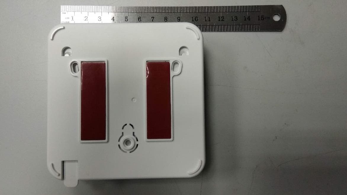
YXG-ES700TRKPD
Oct 08, 2020Tag Reader with Keypad
Equipment Class
DXX - Part 15 Low Power Communication Device Transmitter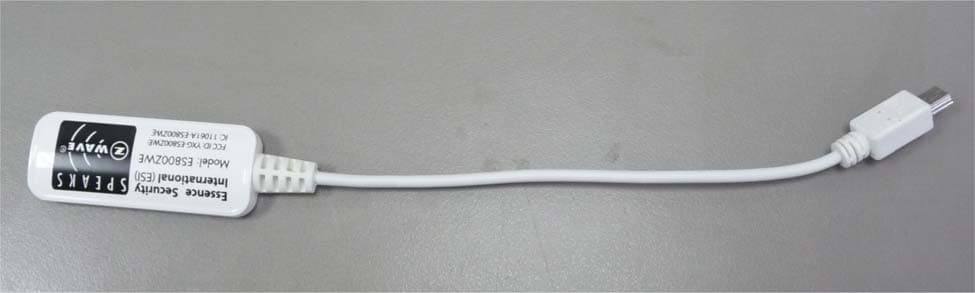
YXG-ES800ZWE
Sep 01, 2015Z-Wave extender
Equipment Class
DSR - Part 15 Remote Control/Security Device Transceiver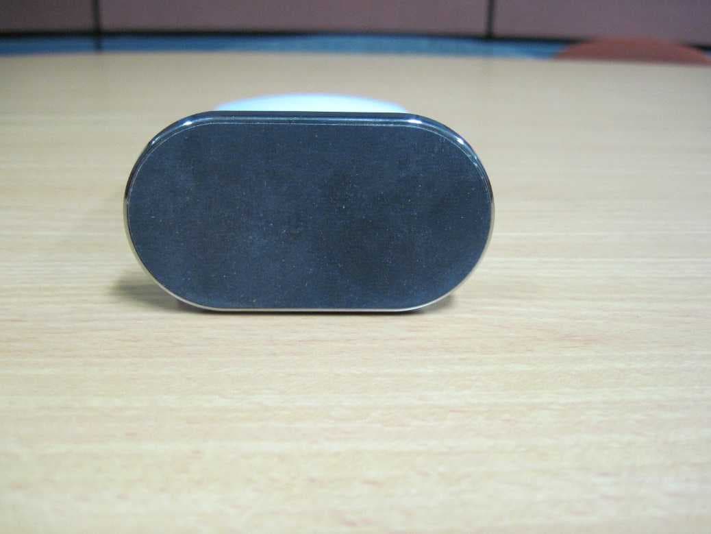
YXG-ES8000WG
Jul 08, 2015WeRATHome Hub ES8000WG
Equipment Class
DTS - Digital Transmission System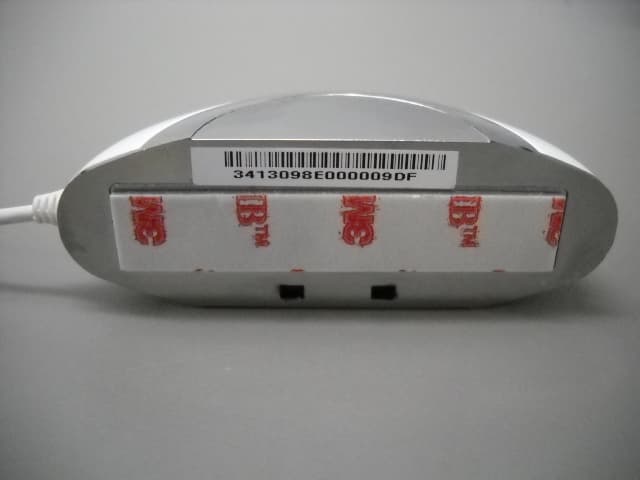
YXG-ES800FL
Mar 10, 2014Flood detector
Equipment Class
DTS - Digital Transmission System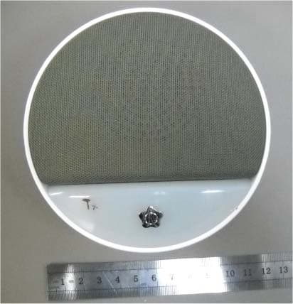
YXG-ES700ISN
Jan 26, 2014Indoor siren
Equipment Class
DSR - Part 15 Remote Control/Security Device Transceiver