YXG-ES800ZWDZ-wave controller
Essence Security International ltd.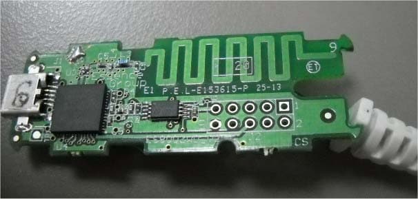
Click to zoom
Application Details
- Equipment Class
- DXT - Part 15 Low Power Transceiver, Rx Verified
- Date of Grant
- Aug 28, 2013
- Application Purpose
- Original Equipment
- Date of Application
- Aug 26, 2013
- Equipment Note
- Z-wave controller
- Frequency Range
- 908.42000000 - 908.42000000
- Country
- Israel
Documents & Files
Document Text
Text extracted from the exhibit documents filed with the FCC. Open a document above to read the original.
Users Manual
Z-Wave ® Controller ES800ZWD (V3) Incorporating Z-Wave ® Devices into the We.R ™ System With millions of systems and security peripherals installed internationally, Essence Security is a technological and market leader in the field of advanced security solutions for homes, offices and full-service central monitoring stations The ES800ZWD Z-Wave controller integrates with the EverGuard and EverGuard Express control panels and with 3 rd party Z-Wave compatible devices part of the Essence Group Single element – A lightweight Z-Wave® controller Powered by the We.R ™ Central Control Unit Simple and fast pairing process Supported Z-wave® devices – binary switch (on/off) and dimmer, thermostat and door lock ES800ZWD Z-Wave Controller DESCRIPTION: •The Z-Wave® controller allows incorporation of 3rd party Z-Wave® compatible devices into the We.R™ system thus integrating Smart Home applications with Essence security system •To incorporate a 3 rd party device in the Essence system, the Z-Wave® controller connects on one side to the Essence Control Panel and on the other to the 3 rd party device. COMMUNICATION: •Maximum RF range 500m (1640 ft) open air •Z-Wave® bi-directional radio protocol (onboard) Essence Security International (E.S.I.) Ltd. www.essence-grp.com +972-73-244-7777 [email protected] © 2013 Essence Security International (E.S.I.) Ltd. Information contained within this document may change without notice. Certifications and approvals: This device complies with FCC Rules Part 15 and with Industry Canada license-exempt RSS standard(s). Operation is subject to the following two conditions: (1) This device may not cause harmful interference, and (2) This device must accept any interference received, including interference that may cause undesired operation Le présent appareil est conforme aux CNR d'Industrie Canada applicables aux appareils radio exempts de licence. L'exploitation est autorisée aux deux conditions suivantes: (1) l'appareil ne doit pas produire de brouillage, et (2) l'utilisateur de l'appareil doit accepter tout brouillage radioélectrique subi, même si le brouillage est susceptible d'en compromettre le fonctionnement. NOTE: This equipment has been tested and found to comply with the limits for a Class B digital device, pursuant to part 15 of the FCC Rules. These limits are designed to provide reasonable protection against harmful interference in a residential installation. This equipment generates, uses and can radiate radio frequency energy and, if not installed and used in accordance with the instructions, may cause harmful interference to radio communications. However, there is no guarantee that interference will not occur in a particular installation. If this equipment does cause harmful interference to radio or television reception, which can be determined by turning the equipment off and on, the user is encouraged to try to correct the interference by one or more of the following measures: - Reorient or relocate the receiving antenna. - Increase the separation between the equipment and receiver. - Connect the equipment into an outlet on a circuit different from that to which the receiver is connected. - Consult the dealer or an experienced radio/TV technician for help. Changes or modifications to this equipment not expressly approved by the party responsible for compliance (Essence Ltd.) could void the user’s authority to operate the equipment. •Frequency: 868.4/908.4/921.4 MHz •Bit Rate: 9.6/40 kbps SECURITY: •Data Security – 128bit AES encryption •Unique electronic serial number POWER CONSUMPTION: •Efficient power consumption to extend the operation period SIZE and WEIGHT: •Z-Wave® controller = H: 5mm (0.2 in.), L: 58mm (2.28 in.), W: 24mm 0. 94 in.) •Cable length = 15cm (5.9 in.) •Z-Wave® controller = 10 grams (0.03 lb) ENVIRONMENT: •Storage Temperature: -20 o C – +50 o C (-4 o F–+122 o F) •Operating Ambient Temperature range: 0 o C – +50 o C (+32 o F – +122 o F) •Humidity: Up to 95% non-condensing
External Photos
Essence Security International Ltd. FCC ID:YXG-ES800ZWD IC:11061A-ES800ZWD Page 1 of 5 EXTERNAL PHOTOGRAPHS This document contains 4 photographs Essence Security International Ltd. FCC ID:YXG-ES800ZWD IC:11061A-ES800ZWD Page 2 of 5 Photograph No.1 ES800ZWD Z-wave controller general view Essence Security International Ltd. FCC ID:YXG-ES800ZWD IC:11061A-ES800ZWD Page 3 of 5 Photograph No.2 ES800ZWD Z-wave controller front view Essence Security International Ltd. FCC ID:YXG-ES800ZWD IC:11061A-ES800ZWD Page 4 of 5 Photograph No.3 ES800ZWD Z-wave controller rear side view Essence Security International Ltd. FCC ID:YXG-ES800ZWD IC:11061A-ES800ZWD Page 5 of 5 Photograph No.4 ES800ZWD Z-wave controller side view
ID Label/Location Info
Essence Security International Ltd. FCC ID:YXG-ES800ZWD IC:11061A-ES800ZWD Page 1 of 1 Label The label is affixed on the rear side of the Z-wave controller as shown below. The label material is PVC with a permanent adhesive. Label location Label with FCC ID:YXG-ES800ZWD and IC:11061A-ES800ZWD will be located here. The statement according to FCC part 15 §15.19(a)(3) is placed in User’s Manual, page 2 (Application exhibit User_manual_24589). FCC ID:YXG-ES800ZWD IC:11061A-ES800ZWD
Internal Photos
Essence Security International Ltd. FCC ID:YXG-ES800ZWD IC:11061A-ES800ZWD Page 1 of 3 INTERNAL PHOTOGRAPHS This document contains 2 photographs Essence Security International Ltd. FCC ID:YXG-ES800ZWD IC:11061A-ES800ZWD Page 2 of 3 Photograph No.1 ES800ZWD Z-wave controller PCB front view Essence Security International Ltd. FCC ID:YXG-ES800ZWD IC:11061A-ES800ZWD Page 3 of 3 Photograph No.2 Z-wave controller PCB second side view
Operational Description
For more information, go to: www.essence-grp.com/pages/WeR/Home The ES800ZWD is a Z-Wave® controller dongle integrating into the We.R™ Control Panel (ES8000GP) to allow incorporation of 3 rd party Z-Wave® devices into the We.R ™ system and thus integrating Smart Home applications with Essence security system. It features: •Single element – A lightweight Z-Wave® controller •Fully compatible with the We.R™ system •Powered by the We.R™ Control Panel’s power adaptor •Low Power consuming •Simple and fast pairing process •Supported Z-wave® devices – binary switch (on/off/dimmer), thermostat and door lock •Easy to install •Utilizes cutting-edge technology •Radio Modulation, Frequency, Data Rate and Nominal Radio Coverage: 2FSK for 9.6/40 Kbps, 2GFSK for 100 Kbps Main frequency – US 908.40/908.42MHz, EU 868.40/868.42MHz SAW filter – US Center frequency = 908MHz with BW≤20MHz, EU 868MHz with BW≤20MHz Data Rate – 9.6/40 Kbps (NRZ) Nominal Radio Coverage – 400 meters Operational Description Certifications and approvals: © 2013 Essence Security International (E.S.I.) Ltd. Information contained within this document may change without notice Z-Wave ® Controller ES800ZWD (V3) Incorporating Z-Wave ® Devices into the We.R ™ System For more information, go to: www.essence-grp.com/pages/WeR/Home The Control Panel’s mains power adapter provides the power directly to the Z-Wave ® Controller board and through the board – to the Control Panel. The board’s Z-Wave ® -specific micro-controller communicates data with the We.R™ Control Panel through a UART serial port and interacts via the RF notch filter with the Z-Wave ® end devices. © 2013 Essence Security International (E.S.I.) Ltd. Information contained within this document may change without notice Block Diagram Description
Test Report
Hermon Laboratories Ltd. Harakevet Industrial Zone, Binyamina 30500, Israel Tel. +972-4-6288001 Fax. +972-4-6288277 E-mail: [email protected] Page 1 of 52 Report ID: ESSRAD_FCC.24589.docx Date of Issue: 8-Aug-13 ELECTRICAL TESTING 0839.01 TEST REPORT ACCORDING TO: FCC 47 CFR PART 15 subpart C, section 15.249; subpart B and RSS-210 issue 8 Annex 2; CES-003 Issue 5:2012 FOR: Essence Security International Ltd. Z-Wave Controller Model: ES800ZWD FCC ID:YXG-ES800ZWD IC:11061A-ES800ZWD This report is in conformity with ISO/ IEC 17025. The "A2LA Accredited" symbol endorsement applies only to the tests and calibrations that are listed in the scope of Hermon Laboratories accreditation. The test results relate only to the items tested. This test report shall not be reproduced in any form except in full with the written approval of Hermon Laboratories Ltd. Report ID: ESSRAD_FCC.24589.docx Date of Issue: 8-Aug-13 Page 2 of 52 Table of contents 1 Applicant information ..................................................................................................................................................... 3 2 Equipment under test attributes .................................................................................................................................... 3 3 Manufacturer information .............................................................................................................................................. 3 4 Test details .................................................................................................................................................................... 3 5 Tests summary .............................................................................................................................................................. 4 6 EUT description ............................................................................................................................................................. 5 6.1 General information ....................................................................................................................................................... 5 6.2 Ports and lines .............................................................................................................................................................. 5 6.3 Support and test equipment .......................................................................................................................................... 5 6.4 Changes made in EUT .................................................................................................................................................. 5 6.5 Test configuration .......................................................................................................................................................... 5 6.6 EUT test positions ......................................................................................................................................................... 6 6.7 Transmitter characteristics ............................................................................................................................................ 7 7 Transmitter tests according to 47CFR part 15 subpart C and RSS-210 requirements ................................................. 8 7.1 Field strength of emissions ............................................................................................................................................ 8 7.2 Band edge emission .................................................................................................................................................... 20 7.3 Conducted emissions .................................................................................................................................................. 24 7.4 Antenna requirements ................................................................................................................................................. 27 7.5 Occupied bandwidth test ............................................................................................................................................. 28 8 Unintentional emissions .............................................................................................................................................. 31 8.1 Conducted emissions .................................................................................................................................................. 31 8.2 Radiated emission measurements .............................................................................................................................. 35 9 APPENDIX A Test equipment and ancillaries used for tests ....................................................................................... 41 10 APPENDIX B Measurement uncertainties ................................................................................................................... 42 11 APPENDIX C Test laboratory description ................................................................................................................... 43 12 APPENDIX D Specification references ....................................................................................................................... 43 13 APPENDIX E Test equipment correction factors ......................................................................................................... 44 14 APPENDIX F Abbreviations and acronyms ................................................................................................................. 52 Report ID: ESSRAD_FCC.24589.docx Date of Issue: 8-Aug-13 Page 3 of 52 1 Applicant information Client name: Essence Security International Ltd. Address: 12 Abba Eban avenue, Ackerstein Tower Bldg. D,P.O.Box 2073, Herzliya 4612001, Israel Telephone: +972 7324 47735 Fax: +972 9772 9962 E-mail: ilyaf…
Text truncated - open the document above for the full version.
Test Setup Photos
Essence Security International Ltd. FCC ID:YXG-ES800ZWD IC:11061A-ES800ZWD Page 1 of 7 SETUP PHOTOGRAPHS This document contains 6 photographs Essence Security International Ltd. FCC ID:YXG-ES800ZWD IC:11061A-ES800ZWD Page 2 of 7 Photograph No.1 Setup for carrier field strength measurements at the OATS Essence Security International Ltd. FCC ID:YXG-ES800ZWD IC:11061A-ES800ZWD Page 3 of 7 Photograph No.2 Setup for field strength emission measurements, EUT close view Essence Security International Ltd. FCC ID:YXG-ES800ZWD IC:11061A-ES800ZWD Page 4 of 7 Photograph No.3 Setup for spurious emission field strength measurements in the anechoic chamber below 30 MHz Essence Security International Ltd. FCC ID:YXG-ES800ZWD IC:11061A-ES800ZWD Page 5 of 7 Photograph No.4 Setup for spurious emission field strength measurements in the anechoic chamber in 30 – 1000 MHz range Essence Security International Ltd. FCC ID:YXG-ES800ZWD IC:11061A-ES800ZWD Page 6 of 7 Photograph No.5 Setup for spurious emission field strength measurements in the anechoic chamber above 1000 MHz range Essence Security International Ltd. FCC ID:YXG-ES800ZWD IC:11061A-ES800ZWD Page 7 of 7 Photograph No.6 Setup for conducted emission measurements at AC power lines
Contact Information
Applicant
Tal Cohen(Certification Manager)
Technical Contact
Hermon Laboratories Ltd.Michael Nikishin
[email protected]972 4626 8440
Harakevet Industrial zone, · Israel
Non-Technical Contact
Essence Security International Ltd.Amir Boim
[email protected]972 7324 47902
Test Firm
Hermon LaboratoriesGeorge Shleimovich
Technical Specifications
| # | Rule Parts | Frequency Range | Power Output |
|---|---|---|---|
| 1 | 15C | 908.42 MHz - 908.42 MHz | - |
Other Applications from Essence Security International ltd.
YXG-ES700TRKPD
Oct 08, 2020Tag Reader with Keypad
Equipment Class
DXX - Part 15 Low Power Communication Device Transmitter
YXG-ES800ZWE
Sep 01, 2015Z-Wave extender
Equipment Class
DSR - Part 15 Remote Control/Security Device Transceiver
YXG-ES8000WG
Jul 08, 2015WeRATHome Hub ES8000WG
Equipment Class
DTS - Digital Transmission System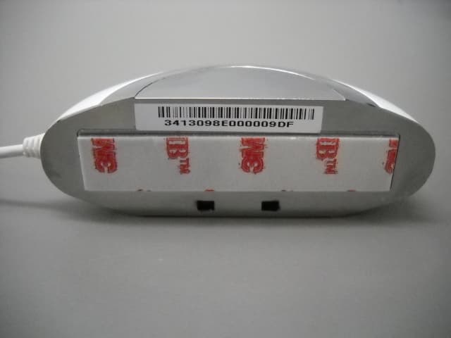
YXG-ES800FL
Mar 10, 2014Flood detector
Equipment Class
DTS - Digital Transmission System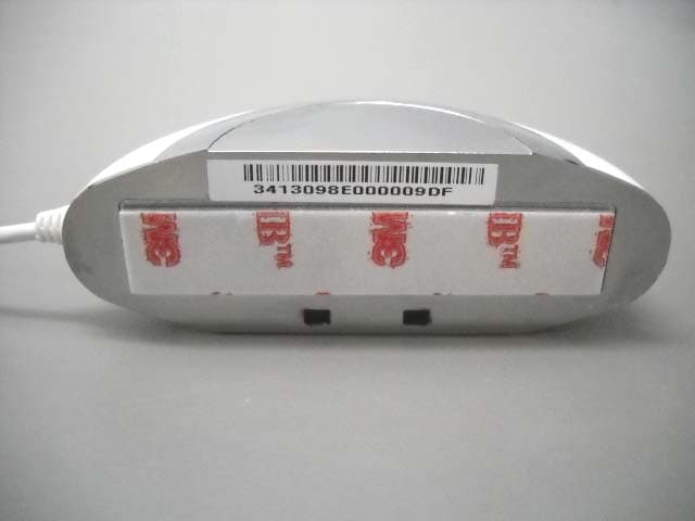
YXG-ES800UT
Mar 09, 2014Universal transmitter
Equipment Class
DTS - Digital Transmission System