Z3M-GCM10LIGHTING CONTROLLER,JN,BUTTON,4CH
Greenwave Reality Inc. d/b/a Greenwave Systems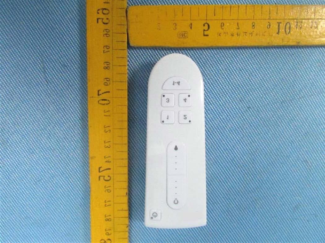
Click to zoom
Application Details
- Equipment Class
- DXX - Part 15 Low Power Communication Device Transmitter
- Date of Grant
- Feb 26, 2013
- Application Purpose
- Original Equipment
- Date of Application
- Feb 26, 2013
- Equipment Note
- LIGHTING CONTROLLER,JN,BUTTON,4CH
- Frequency Range
- 2405.00000000 - 2480.00000000
- Country
- United States
Documents & Files
Document Text
Text extracted from the exhibit documents filed with the FCC. Open a document above to read the original.
Users Manual
Connected Lighting Introduction 2 Installation and Setup 22 Smart Device Application 32 Web Application 51 Remote Control 65 Frequently Asked Questions 73 Troubleshooting 75 Safety Information 79 About GreenWave Reality 82 Product Specifications 83 Table of Contents Connected Lighting Introduction The GreenWave Reality energy management system helps create a smart, energy-efficient home by monitoring and controlling your appliances, electronics, and lighting. You can conserve energy with minimal impact to your lifestyle by using our products to easily manage your devices. Simply connect the Gateway to your home network, plug your devices into our PowerNodes, connect your network light bulbs, and then monitor and control the your power usage through a Web browser or smartphone application. 2 4 Connected Lighting • Any of the following Web browsers Microsoft Internet Explorer 8.0 and above Mozilla Firefox 3.6 and above Google Chrome 12.0 and above Apple Safari 5.1.1 and above Smart Devices (Smartphone, Tablet, and TV) • For Android devices: Android operating system 2.2 and above Screen resolution of 320x240 and above • For Apple devices: iOS operating system 4.2.1 and above Wireless Router For the smart device application to manage your lighting locally within your home, your home network must use a wireless router to which your smart device is connected. While you can also connect remotely to your lighting network over the Internet or mobile data connection, it is not practical to do so on a day-to-day basis at home. Connected Lighting Overview The Connected Lighting kit includes a wireless smart lighting system that helps make the lighting in your home more energy efficient and easier to manage. The kit includes LED or CFL light bulbs and a remote control that work together to help you manage your lighting wirelessly. Your lighting kit also includes a Gateway, which provides an enhanced network connection to your light bulbs. This Gateway connection allows you to use your Web browser, smartphone, or other smart devices to set up and manage your home lighting system as well as set up user-defined schedules and other controls for automatically turning your lighting on or off. Note: This guide uses the term “smart device” to refer to a smartphone, tablet (or iPod touch), or TV. System Requirements To use a Web browser or smart device to manage your Connected Lighting, your computer or smart device and home network must meet the following minimum requirements. If your system does not meet these requirements, you can still use your lighting kit with the remote control. Computer (for Web Access) • Active Internet connection (only if accessing your account remotely) 6 Connected Lighting There are no requirements for the type of wireless router, as long as your smart device and Gateway are able to connect to it. Refer to your smart device’s documentation for more information on connecting it to your home network. Note: Connected Lighting is designed for a wireless home network and not a corporate network. Gateway Components 1. Sync button and activity indicator: Button that you press to search and add new light bulbs and devices. If your equipment came with the Gateway as part of an energy management kit, then you typically do not have to use the sync button since the Gateway and other energy management devices were already synced at the factory. However, if you do have to sync your equipment, refer to the Installation and Setup chapter for more information. The button also has an indicator that shows the sync status with your energy management devices. Refer to the Gateway Activity Indicators section later in this chapter for descriptions of each of the indicators you might see during the sync process. 2. WAN (Internet connection) error indicator: Indicator that shows whether or not the Gateway is connected to the internet. Refer to the Gateway Activity Indicators section later in this chapter for more information. 3. LAN (home network) error indicator: Indicator that shows whether or not the Gateway is connected to your network. Refer to the Gateway Activity Indicators section later in this chapter for more information. 4. Power indicator: Indicator that shows whether or not the Gateway is powered. Refer to the Gateway Activity Indicators section later in this chapter for more information. 5. Network socket (RJ45): Ethernet port to connect the Gateway to your network router or modem. 6. Power adapter socket: Socket to plug in the Gateway power adapter. 1 2 3 4 5 6 8 Connected Lighting Power Indicator—off (no color): The Gateway is powered off. Power Indicator—Steady white: The Gateway is powered on. Sync button— two green bars rotating clockwise: The Gateway is in comissioning mode to connect with network light bulbs. The commissioning process will continue until all light bulbs and devices searching for network have been found. If no devices are found for 2 consecutive mintues the commissioning process will time out. Network indicator—off (no color): The Gateway is connected to your home network. Network indicator—red: The Gateway is not connected to your home network. Check that the Ethernet cable is plugged into the Gateway and your network router or modem. Refer to the Installation and Setup chapter for more more information. Internet indicator—off (no color): The Gateway is connected to the Internet. Internet indicator—red: The Gateway is not connected to the Internet. If your network indicator is also red, then the problem may be with the Gateway’s connection to your network router or modem (refer to the network indicator information above). Otherwise, check that your network router or modem has an active Internet connection. Gateway Activity Indicators Your Gateway has sync, network, and power indicators that display the following patterns and colors to show you the Gateway’s current status: Remote Control Components 1. 1-4 button: Button that you press to select all lighting groups to …
Text truncated - open the document above for the full version.
Block Diagram
RF Board Main Control Board
External Photos
ReferenceNo.:WTD13S0100362EPage38of44 WaltekServices(Shenzhen)Co.,Ltd. http://www.waltek.com.cn 12 12 12 12Photographs Photographs Photographs Photographs- - - -Constructional Constructional Constructional ConstructionalDetails Details Details Details 12.1 12.1 12.1 12.1EUT EUT EUT EUT– – – –External External External ExternalView View View View ReferenceNo.:WTD13S0100362EPage39of44 WaltekServices(Shenzhen)Co.,Ltd. http://www.waltek.com.cn ReferenceNo.:WTD13S0100362EPage40of44 WaltekServices(Shenzhen)Co.,Ltd. http://www.waltek.com.cn
ID Label/Location Info
FCC Label Location for model: CM100-1-GR The Label must not be a stick-on paper. The Label on these products must be permanently affixed to the product and readily visible at the time of purchase and must last the expected lifetime of the equipment not be readily detachable. The follow note is stated into user manual since there is no enough place. THIS DEVICE COMPLIES WITH PART 15 OF THE FCC RULES. OPERATION IS SUBJECT TO THE FOLLOWING TWO CONDITIONS: (1) THIS DEVICE MAY NOT CAUSE HARMFUL INTERFERENCE, AND (2) THIS DEVICE MUST ACCEPT ANY INTERFERENCE RECEIVED, INCLUDING INTERFERENCE THAT MAY CAUSE UNDESIRED OPERATION.
ID Label/Location Info
Reference No.: WTD13S0100362E Page 44 of 44 Waltek Services (Shenzhen) Co.,Ltd. http://www.waltek.com.cn 13 FCC ID Label 13.1 Label sample Label sample for model: CM100-1-GR The follow note is stated into user manual since there is no enough place. THIS DEVICE COMPLIES WITH PART 15 OF THE FCC RULES. OPERATION IS SUBJECT TO THE FOLLOWING TWO CONDITIONS: (1) THIS DEVICE MAY NOT CAUSE HARMFUL INTERFERENCE, AND (2) THIS DEVICE MUST ACCEPT ANY INTERFERENCE RECEIVED, INCLUDING INTERFERENCE THAT MAY CAUSE UNDESIRED OPERATION. ==End of report==
Internal Photos
EUT – Internal View EUT with 10 pins connector EUT without 10 pins connector RF Module
Operational Description
Operational description This is a remote control to control light ‐ bulbs wirelessly. The system included two parts of PCB circuitries, RF module board and main control board. The RF module board supported by an ultra low power high performance IEEE802 15 4 wireless The RF module board supported by an ultra low power high performance IEEE802 . 15 . 4 wireless microcontroller, JN5168, operated at 2.4GHz to 2.48GHz,Oscillator is 32MHz. It had a printed circuit Antenna for the wireless transmission. The RF module board is soldered directly on the main control board. The main control board included all the functional keys circuitry and LEDs eg o n/off button brightness control The main control board included all the functional keys circuitry and LEDs eg o n/off button , brightness control button and lighting group number buttons. These function keys are control by the wireless microcontroller through the GPIO data registers. The whole system is operated at 3V with two AAA batteries The whole system is operated at 3V with two AAA batteries .
Schematics
11 22 33 44 55 66 D D C C B B A A Title Number Revision Size B Date: 2013-1-10 Sheet of File: C:\Documents and Settings\..\Remote 20130103.Sch Drawn By: BT1 BATTERY LED1ROOM 1 R222M 1%R231M 1% R26680R SW5 SW-SKHR C12 100nF/16V C110nF C210nF C310nF C410nF 1 2 3 4 5 6 7 8 9 10 J1HEADER 5X2 VCC 15 GND 16 GND 1 GND 29 RESETN 12 SPIMISO 17 SPIMOSI 18 SPISEL0 19 DIO6 2 DIO7 3 DIO8 4 DIO9 5 DIO10 6 DIO11 7 DIO12 8 DIO13 9 DIO14 10 DIO15 11 DIO16 13 DIO17 14 ADC2 21 ADC1 22 DIO0 23 DIO1 24 DIO2 25 DIO3 26 DIO4 27 DIO5 28 SPICLK 20 M12.4G MODULE Q12N7002A Q22N7002A ADC1 DIO5 VCC DIO16 LED2ROOM 2 R27680R Q32N7002A DIO9 LED3R00M 3 R28680R Q42N7002A DIO17 LED4ROOM 4 R29680R Q52N7002A DIO2 LED5ACTIVITY R30 680R Q62N7002A DIO14 VCC SW6 DIMMER SW7BRIGHTEN SW8ON/OFF SW1ROOM 4 SW2ROOM 3 SW3 ROOM 2 SW4 ROOM 1 C610nF C710nF C810nF C510nF DIO13DIO8DIO12DIO3DIO15DIO0DIO10DIO1 DIO8DIO9DIO11 DIO13 DIO16 DIO17 DIO1DIO2 DIO0 DIO5 DIO10DIO12 DIO14 DIO15 ADC1 UART_TXD0 UART_RXD0 DIO3 JN_SPIMISO JN_SPIMISO RESET_N RESET_N DIO5 UART_RXD0 UART_TXD0 R19 0R SW9 ALL ROOMS R18 0R R20R R1010K VCC DIO4 DIO4 SPICLK SPICLK
Test Report
Reference No.: WTD13S0100362E Page 1 of 44 FCC TEST REPORT Waltek Services (Shenzhen) Co.,Ltd. http://www.waltek.com.cn FCC ID : Z3M-GCM10 Applicant : Greenwave Reality Pte Ltd Address : 41 Science Park Road, #03-01, The Gemini, Science Park II, Singapore Manufacturer : the same as above Address : the same as above Equipment Under Test (EUT) : Product Name : Lighting Controller,JN,Button,4ch Model No. : CM1UV-Y-XX(“U” stands for “0-9/A-Z”; “V” stands for “0-9; “Y” stands for “0- 9/A-Z”; “XX” stands for “00-99/AA-ZZ”) Rules : FCC CFR47 Part 15 Section 15.249: 2010, Date of Test : January 8~22,2013 Date of Issue : January 23,2013 Test Result : PASS* Remark: * The sample described above has been tested to be in compliance with the requirements of the rules listed above. The results shown in this test report refer only to the sample(s) tested, this test report cannot be reproduced, except in full, without prior written permission of the company. The report would be invalid without specific stamp of test institute and the signatures of compiler and approver. PERPARED BY: Waltek Services (Shenzhen) Co., Ltd. 1/F, Fukangtai Building, West of Baima Road., Songgang Street, Bao’an District, Shenzhen, China Tel: +86-755-83551033 Fax: +86-755-83552400 Compiled by: Approved by: Zero Zhou / Project Engineer Philo Zhong / Manager Reference No.: WTD13S0100362E Page 2 of 44 Waltek Services (Shenzhen) Co.,Ltd. http://www.waltek.com.cn 2 Test Summary Test Items Test Requirement Result Restricted Band 15.205 PASS Occupied Bandwidth 15.215c PASS Conducted Emissions 15.207 N/A Radiated Emission 15.205(a) 15.209 15.249(a) 15:249(d) PASS Antenna Requirement 15.203 PASS Reference No.: WTD13S0100362E Page 3 of 44 Waltek Services (Shenzhen) Co.,Ltd. http://www.waltek.com.cn 3 Contents Page 1 COVER PAGE ............................................................................................................................................ 1 2 TEST SUMMARY .................................................................................................................................................... 2 3 CONTENTS .............................................................................................................................................................. 3 4 GENERAL INFORMATION ................................................................................................................................... 4 4.1 GENERAL DESCRIPTION OF E.U.T. ............................................................................................................. 4 4.2 DETAILS OF E.U.T. ...................................................................................................................................... 4 4.3 TEST FACILITY .............................................................................................................................................. 4 4.4 TEST LOCATION ............................................................................................................................................ 4 4.5 GENERAL CONDITION ................................................................................................................................... 5 4.5.1 Environmental condition of test site ............................................................................................................. 5 4.5.2 Test Mode ..................................................................................................................................................... 5 5 EQUIPMENT USED DURING TEST .................................................................................................................... 6 5.1 EQUIPMENTS LIST ........................................................................................................................................ 6 5.2 MEASUREMENT UNCERTAINTY .................................................................................................................... 6 5.3 TEST EQUIPMENT CALIBRATION .................................................................................................................. 6 6 CONDUCTED EMISSION TEST ........................................................................................................................... 7 7 RADIATION EMISSION TEST .............................................................................................................................. 8 7.1 EUT OPERATION: ........................................................................................................................................ 8 7.2 TEST SETUP ................................................................................................................................................. 9 7.3 SPECTRUM ANALYZER SETUP ..................................................................................................................... 9 7.4 TEST PROCEDURE ..................................................................................................................................... 10 7.5 CORRECTED AMPLITUDE & MARGIN CALCULATION .................................................................................. 10 7.6 RADIATED EMISSIONS TEST RESULT ......................................................................................................... 10 7.7 RADIATED EMISSION DATA ........................................................................................................................ 11 8 OCCUPIED BANDWIDTH ................................................................................................................................... 23 8.1 TEST PROCEDURE ..................................................................................................................................... 23 8.2 TEST RESULT ............................................................................................................................................. 23 9 RESTRICTED BA…
Text truncated - open the document above for the full version.
Test Setup Photos
Reference No.: WTD13S0100362E Page 37 of 43 Waltek Services (Shenzhen) Co.,Ltd. http://www.waltek.com.cn 11 Photographs of Testing 11.1 Radiation Emission From 30MHz-1GHz 11.2 Radiation Emission From Above 1GHz
Contact Information
Applicant
Troy Pliska(Executive VP of Operations)
Test Firm
Waltek Services(Shenzhen) Co., Ltd.Philo zhong
Technical Specifications
| # | Rule Parts | Frequency Range | Power Output |
|---|---|---|---|
| 1 | 15C | 2.40 GHz - 2.48 GHz | - |
Other Applications from Greenwave Reality Inc. d/b/a Greenwave Systems
Z3M-GSYP1J11
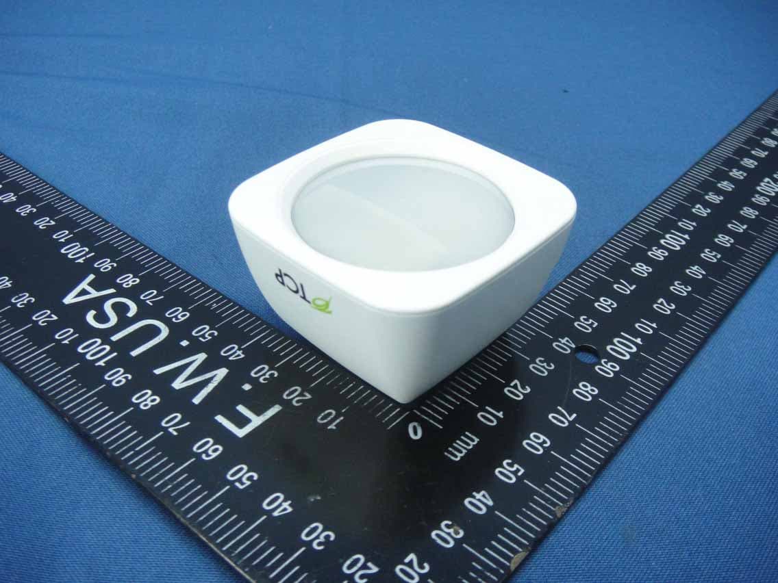
Jul 14, 2014Wireless Motion Sensor
Equipment Class
DTS - Digital Transmission System
Z3M-GUBW1J1
Apr 28, 2014Lighting Gateway
Equipment Class
DTS - Digital Transmission System
Z3M-ZBMOD1
Jan 16, 2014Zigbee Wireless Module
Equipment Class
DTS - Digital Transmission System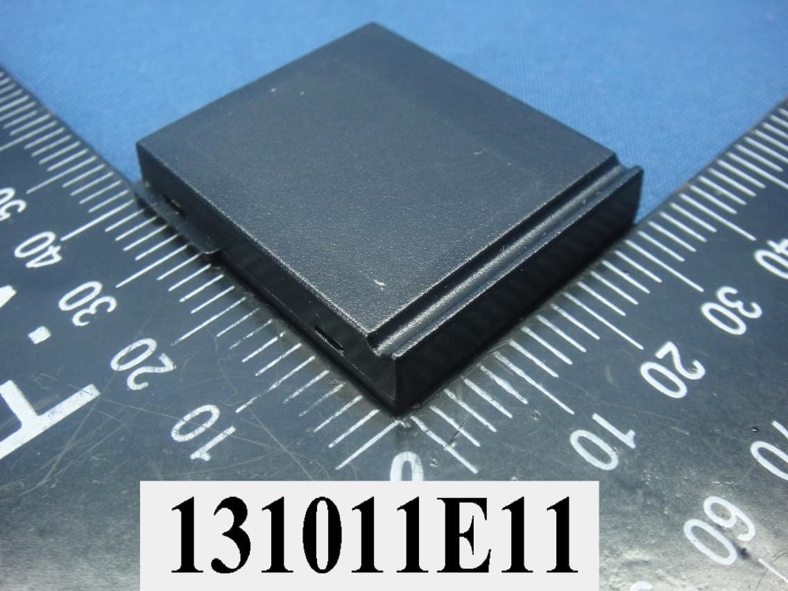
Z3M-JENMOD1
Jan 16, 2014Zigbee Wireless Module
Equipment Class
DTS - Digital Transmission System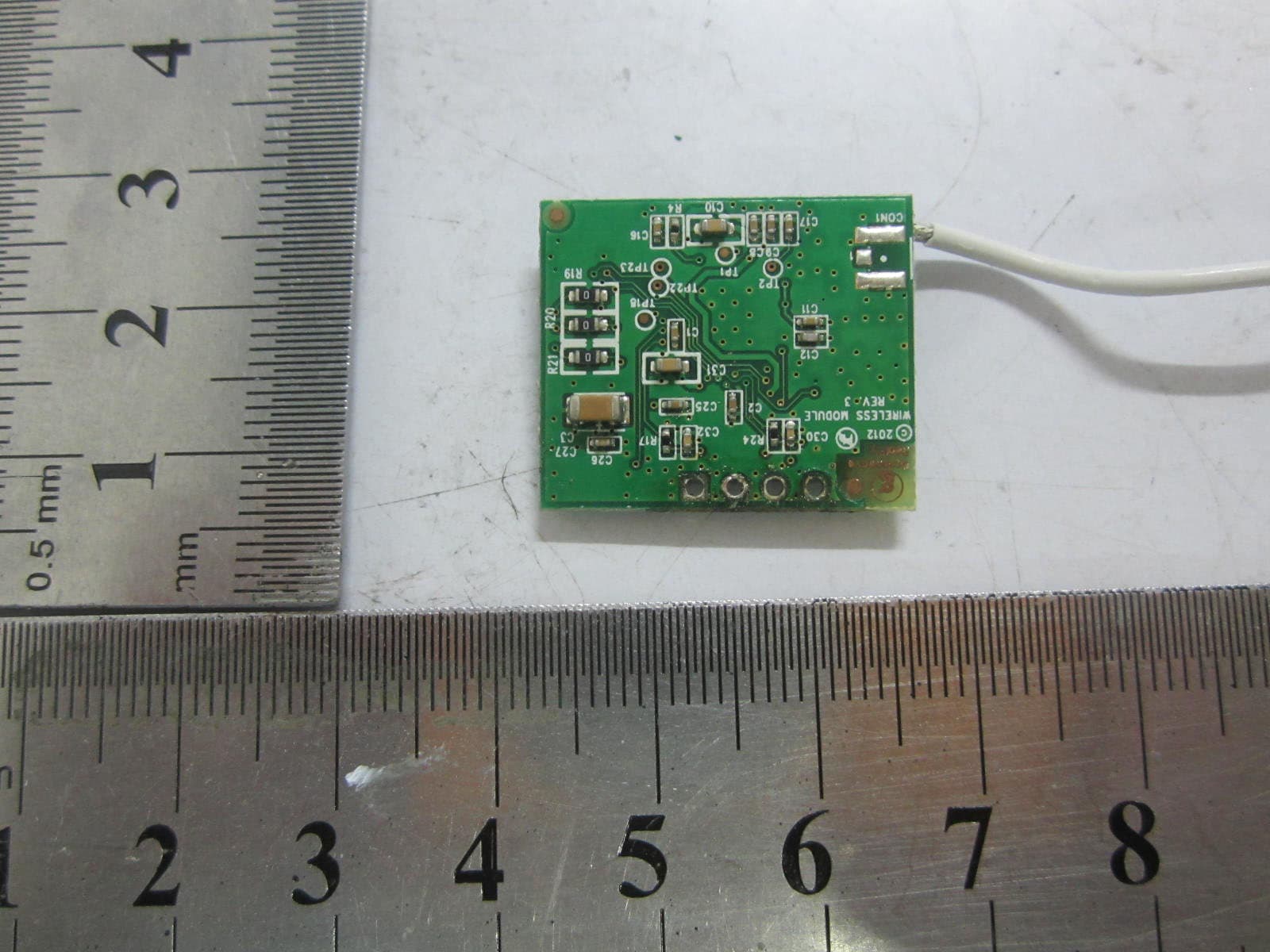
Z3M-GLA19147IAJNW
Nov 18, 2012Self-Ballasted LED-lamps
Equipment Class
DXX - Part 15 Low Power Communication Device Transmitter