Z3M-GUBW1J1Lighting Gateway
Greenwave Reality Inc. d/b/a Greenwave Systems
Click to zoom
Application Details
- Equipment Class
- DTS - Digital Transmission System
- Date of Grant
- Apr 28, 2014
- Application Purpose
- Original Equipment
- Date of Application
- Apr 28, 2014
- Equipment Note
- Lighting Gateway
- Frequency Range
- 2405.00000000 - 2480.00000000
- Country
- United States
Documents & Files
Document Text
Text extracted from the exhibit documents filed with the FCC. Open a document above to read the original.
Users Manual
Connected Lighting User Guide With Lighting Gateway and Remote Control Introduction The GreenWave Reality Smart Home Platform helps create a smart, energy-efficient home by monitoring and controlling your appliances, electronics, and lighting. You can conserve energy with minimal impact to your lifestyle by using our products to easily manage your devices. Simply connect the Gateway or Lighting Gateway to your home network, plug your devices into our PowerNodes, connect your network light bulbs, and then monitor and control the your power usage through a smart device application. Connected Lighting Overview The Connected Lighting kit includes a wireless smart lighting system that helps make the lighting in your home more energy efficient and easier to manage wirelessly. The lighting solution consists of high- quality, connected LED bulbs from our partners, a hand-held remote controller, and an optional Lighting Gateway that allows for complete remote lighting control. • The Energy Star connected LED or CFL light bulbs typically consume about 80% less energy than an equivalent incandescent or halogen bulbs. • The Lighting Remote can control four groups of bulbs and can turn lights on and off or dim them with the touch of a finger. The remote can be used with or without the Lighting Gateway. • The Lighting Gateway is the hub that connects the smart bulbs to your home network and manages powerful Smart Controls and remote access to ensure your scheduled events get activated reliably. • For added convenience and safety, the solution is light switch friendly, meaning that existing wall switches will still turn the light on or off in all circumstances. Smart Device Requirements To use a smart device, smart phone, tablet or tv to manage your Connected Lighting, your smart device must meet the following minimum requirements. If not, you can still use your lighting kit with the remote control. • For Android devices: o Android operating system 2.2 and above Introduction Connected Lighting User Guide | 1 o Screen resolution of 320 x 240 and above • For Apple devices: o iOS operating system 4.2.1 and above Home Network Requirements For the smart device application to manage your lighting locally within your home, your home network must use a wireless router to which your smart device is connected. There are no requirements for the type of wireless router, as long as your smart device and Lighting Gateway are able to connect to it. For more information on connecting your smart device to your home network, refer to your smart device’s documentation. Product Specifications Connected Lighting User Guide | 2 Components Lighting Gateway 1. WPS Button: Connect to home Wifi using WPS 2. Network Icon: indicates your Lighting Gateway is connected to the Wi-Fi network 3. Power Icon: indicates your Lighting Gateway is powered on. 4. Bulb Icon: indicates your light bulbs are connected to your Lighting Gateway. 5. AC Power Plug: plugs into a standard socket and connects your Connected Lighting to your Home Network. Activity Indicators Your Lighting Gateway has power, network, and bulb indicators that show current status: Power indicator—off (no color): Lighting Gateway is powered off. Power indicator—white: Lighting Gateway is powered on. Power indicator — white fading: Lighting Gateway is starting Wi-Fi connection. Network indicator—off (no color): The Gateway is connected to your home network. Network indicator—red: The Gateway is not connected to your home network. Check that the Ethernet cable is plugged into the Gateway and your network router or modem. Refer to the Installation and Setup chapter for more more information. Network indicator—off (no color): Lighting Gateway is connected to the Wi-Fi network. Network indicator—flashing white: The Wi-Fi connection is not configured. Product Specifications Connected Lighting User Guide | 3 Network indicator—solid white for 5 seconds: Lighting Gateway has successfully connected to your Wi-Fi network. Network indicator—solid red for 5 seconds: Lighting Gateway failed to connected to your Wi-Fi network. If no network is found for two consectutive minutes, the process times out. Network indicator—red: Lighting Gateway is not connected to the Internet. If your network indicator is also red, then the problem may be with the Gateway’s connection to your network router or modem (refer to the network indicator information above). Otherwise, check that your network router or modem has an active Internet connection. Bulb indicator—off (no color): Light bulbs are connected to your home network. Bulb indicator—flashing white: Light bulbs are searching a connection to your home network. Indicators —flashing white in sync: Lighting Gateway software is updating. The indicators flash white in order. commissioning mode to connect with network light bulbs. The commissioning process continues until all light bulbs and devices searching for the network have been found. If no devices are found for two consecutive mintues, the commissioning process will time out. Indicators —flashing white for 5 seconds in sync: The lighting kit was successfully reset to the factory settings. Remote Control 1.1-4 button: selects all lighting groups to turn on, turn off, dim, or brighten. 2.Group number button: selects the specific lighting group to turn on, turn off, dim, or brighten as well as programs the lights in the corresponding group. An indicator light above each number indicates the group number currently being used. Product Specifications Connected Lighting User Guide | 4 3.On/Off button: turns on or off the lights in the selected lighting groups. Lights turn on to the previous dimming level. 4.Dimmer control: dims or brightens the lights in the selected lighting groups. 5.Primary status indicator: lights or flashes during different activities with the remote control. 6.Battery compartment: holds 2 AA batteries to power the remote control. 7.Program button: initiate programming of lighting g…
Text truncated - open the document above for the full version.
Attestation Statements
We, Greenwave Reality Pte Ltd declare that the device does not support channel 12 ~ 13 in 2.4GHz band and any non-US channels in all the operational mode(s) for the following product.
Cover Letter(s)
Greenwave Reality Pte Ltd 41 Science Park Road, #03-01, The Gemini, Science Park II, Singapore, 117610 Singapore Federal Communications Commission Authorization and Evaluation Division Date: April 29, 2014 Confidentiality Request FCC ID: Z3M-GUBW1J1 Pursuant to Sections 0.457/0.459 of the commission’s rules, we request short-term confidential treatment for the following information until 2014/10/29 of Equipment Authorization in order to ensure sensitive business information remains confidential until the actual marketing of the device: External Photos Test Setup Photos User’s Manual Internal Photo Thank you! Sincerely yours, ------------------------------------------------------- Freddie Fong/VP of Hardware Engineering Greenwave Reality Pte Ltd Tel: +65 31 5717 04 Fax: +65 67 7976 31 E-mail: [email protected]
External Photos
Report No.: 140221E06 Page 1 CONSTRUCTION PHOTOS OF EUT
ID Label/Location Info
LABEL LOCATION FCC ID: Z3M-GUBW1J1 APPLICATION NEXT ASSY USED ON REV APPROVED DATE REV MATERIAL: DRAWN SIZE DWG TITLE DWG NO. SCALESHEET REV APVD ENGR FINISH: THIRD ANGLE PROJECTION A3 12 12 A B A B UNLESS OTHERWISE SPECIFIED ALL DIMENSIONS INTEGRALDIMENSIONS 1 PLACEDECIMAL AREIN mm ANDTOLERANCES ARE: ANGULAR DIMENSIONS HOLES UNDER5.00ψ 0.5 ± ± ± 0.3 ± 2 0.2 SEE NOTES SEE NOTES A 1/1 1 OF 1 SANDY CHEN HSINYUN LIN HSINYUN LIN 02/11/14 02/11/14 SANDY CHEN 02/11/14 02/11/14 A A RELEASE TO FILE 4L-LRG1107-001 4L-LRG1107-001 DESCRIPTION REVISIONS PART NUMBER BLOCK PART NUMBER LABEL, UL, GREENWAVE, LRG1LABEL, UL, GREENWAVE, LRG1 LRG1 WNC PROPRIETARY No. 20 Park Avenue II, Hsinchu Science Park, Hsinchu 308, Taiwan, R.O.C. Tel: 886-3-666-7799 Fax: 886-3-666-7321 NOTES: 1. MATERIAL: WHITE PET, t=0.075(HTYL75(EB)), 2. COLOR: a. 底色為材質原色 3. TEMPERATURE RESISTANT= 80 0 C. 4. ADHESIVE THICKNESS=0.033 +_ 0.003mm. 5. 捲狀出貨 6. PRODUCT LABEL 參照第二頁相關測試規範 RED: ONLINE PRINTING BLACK 出 標 方 向 33.4 23.0 R0.5,4PLS
Internal Photos
Report No.: 140221E06 Page 2 Report No.: 140221E06 Page 3 Report No.: 140221E06 Page 4 Report No.: 140221E06 Page 5 Rev 2.0 Report No.: 140221E06 Page 6
RF Exposure Info
Report No.: SA140221E06 1 of 6 Report Format Version 5.0.0 RF EXPOSURE REPORT REPORT NO.: SA140221E06 MODEL NO.: UBW1J1-1AXY-ZZ (X= 0~9 or A~Z, Shell Colour ; Y= 0~9 or A~Z, Cosmetic Variant ; Z =0~9 or A~Z, Brand digit #1 ; Z= 0~9 or A~Z, Brand digit #2) FCC ID: Z3M-GUBW1J1 RECEIVED: Feb. 21, 2014 TESTED: Mar. 20, 2014 ISSUED: Apr. 16, 2014 APPLICANT: Greenwave Reality Pte Ltd ADDRESS: 41 Science Park Road, #03-01, The Gemini, Science Park II, Singapore, 117610 Singapore ISSUED BY: Bureau Veritas Consumer Products Services (H.K.) Ltd., Taoyuan Branch Hsin Chu Laboratory LAB ADDRESS: No. 81-1, Lu Liao Keng, 9th Ling,Wu Lung Tsuen, Chiung Lin Hsiang, Hsin Chu Hsien 307, Taiwan, R.O.C. This report should not be used by the client to claim product certification, approval, or endorsement by any government agencies. This report is for your exclusive use. Any copying or replication of this report to or for any other person or entity, or use of our name or trademark, is permitted only with our prior written permission. This report sets forth our findings solely with respect to the test samples identified herein. The results set forth in this report are not indicative or representative of the quality or characteristics of the lot from which a test sample was taken or any similar or identical product unless specifically and expressly noted. Our report includes all of the tests requested by you and the results thereof based upon the information that you provided to us. You have 60 days from date of issuance of this report to notify us of any material error or omission caused by our negligence, provided, however, that such notice shall be in writing and shall specifically address the issue you wish to raise. A failure to raise such issue within the prescribed time shall constitute your unqualified acceptance of the completeness of this report, the tests conducted and the correctness of the report contents. Unless specific mention, the uncertainty of measurement has been explicitly taken into account to declare the compliance or non-compliance to the specification Report No.: SA140221E06 2 of 6 Report Format Version 5.0.0 TABLE OF CONTENTS RELEASE CONTROL RECORD ..................................................................................... 3 1. CERTIFICATION ...................................................................................................... 4 2. RF EXPOSURE LIMIT .............................................................................................. 5 3. MPE CALCULATION FORMULA ............................................................................. 5 4. CLASSIFICATION .................................................................................................... 5 5. ANTENNA GAIN....................................................................................................... 5 6. CALCULATION RESULT OF MAXIMUM CONDUCTED POWER ........................... 6 Report No.: SA140221E06 3 of 6 Report Format Version 5.0.0 RELEASE CONTROL RECORD ISSUE NO. REASON FOR CHANGE DATE ISSUED SA140221E06 Original release Apr. 16, 2014 Report No.: SA140221E06 4 of 6 Report Format Version 5.0.0 1. CERTIFICATION PRODUCT: Lighting Gateway BRAND NAME: GreenWave Reality MODEL NO.: UBW1J1-1AXY-ZZ (X= 0~9 or A~Z, Shell Colour ; Y= 0~9 or A~Z, Cosmetic Variant ; Z =0~9 or A~Z, Brand digit #1 ; Z= 0~9 or A~Z, Brand digit #2) TEST SAMPLE: ENGINEERING SAMPLE APPLICANT: Greenwave Reality Pte Ltd TESTED DATE: Mar. 20, 2014 STANDARDS: FCC Part 2 (Section 2.1091) FCC OET Bulletin 65, Supplement C (01-01) IEEE C95.1 The above equipment (Model: UBW1J1-1A01-TP) has been tested by Bureau Veritas Consumer Products Services (H.K.) Ltd., Taoyuan Branch, and found compliance with the requirement of the above standards. The test record, data evaluation & Equipment Under Test (EUT) configurations represented herein are true and accurate accounts of the measurements of the sample’s EMC characteristics under the conditions specified in this report. PREPARED BY : , DATE: Nov. 19, 2013 ( Midoli Peng, Specialist ) APPROVED BY : , DATE: Nov. 19, 2013 ( May Chen, Manager ) Report No.: SA140221E06 5 of 6 Report Format Version 5.0.0 2. RF EXPOSURE LIMIT LIMITS FOR MAXIMUM PERMISSIBLE EXPOSURE (MPE) FREQUENCY RANGE (MHz) ELECTRIC FIELD STRENGTH (V/m) MAGNETIC FIELD STRENGTH (A/m) POWER DENSITY (mW/cm 2 ) AVERAGE TIME (minutes) LIMITS FOR GENERAL POPULATION / UNCONTROLLED EXPOSURE 300-1500 ... ... F/1500 30 1500-100,000 ... ... 1.0 30 F = Frequency in MHz 3. MPE CALCULATION FORMULA Pd = (Pout*G) / (4*pi*r 2 ) where Pd = power density in mW/cm 2 Pout = output power to antenna in mW G = gain of antenna in linear scale pi = 3.1416 r = distance between observation point and center of the radiator in cm 4. CLASSIFICATION The antenna of this product, under normal use condition, is at least 20cm away from the body of the user. So, this device is classified as Mobile Device. 5. ANTENNA GAIN The antennas provided to the EUT, please refer to the following table: WLAN Antenna Spec. Antenna Type Antenna Connector Gain(dBi) Frequency range (GHz) PCB NA 0.07 2.4~2.4835 Zigbee Antenna Spec. Antenna Type Antenna Connector Gain(dBi) Frequency range (GHz) PCB NA 1.14 2.4~2.4835 Report No.: SA140221E06 6 of 6 Report Format Version 5.0.0 6. CALCULATION RESULT OF MAXIMUM CONDUCTED POWER For WLAN FREQUENCY BAND (MHz) MAX POWER (mW) ANTENNA GAIN (dBi) DISTANCE (cm) POWER DENSITY (mW/ cm 2 ) LIMIT (mW/cm 2 ) 2412-2462 161.808 0.07 20 0.03271 1.00 For Zigbee FREQUENCY BAND (MHz) CONDUCTED POWER (mW) ANTENNA GAIN (dBi) DISTANCE (cm) POWER DENSITY (mW/ cm 2 ) LIMIT (mW/cm 2 ) 2405 - 2480 1.824 1.14 20 0.00047 1.00 CONCLUSION: Both of the WLAN and Zigbee can transmit simultaneously, the formula of calculated the MPE is: CPD 1 / LPD 1 + CPD 2 / LPD 2 + ......etc. < 1 CPD = Calculation power density LPD = Limit of power density Therefore, the worst-case situation is 0.03271 / 1 + 0.00047 / 1= 0.033, which is less than “1”. This confir…
Text truncated - open the document above for the full version.
Test Report
Report No.: RF140221E06 1 of 55 Report Format Version 5.2.0 FCC TEST REPORT (WLAN) REPORT NO.: RF140221E06 MODEL NO.: UBW1J1-1AXY-ZZ (X= 0~9 or A~Z, Shell Colour ; Y= 0~9 or A~Z, Cosmetic Variant ; Z =0~9 or A~Z, Brand digit #1 ; Z= 0~9 or A~Z, Brand digit #2) FCC ID: Z3M-GUBW1J1 RECEIVED: Feb. 21, 2014 TESTED: Feb. 27 to Mar. 28, 2014 ISSUED: Apr. 16, 2014 APPLICANT: Greenwave Reality Pte Ltd ADDRESS: 41 Science Park Road, #03-01, The Gemini, Science Park II, Singapore, 117610 Singapore ISSUED BY: Bureau Veritas Consumer Products Services (H.K.) Ltd., Taoyuan Branch Hsin Chu Laboratory LAB ADDRESS : No. 81-1, Lu Liao Keng, 9th Ling, Wu Lung Tsuen, Chiung Lin Hsiang, Hsin Chu Hsien 307, Taiwan, R.O.C. TEST LOCATION (1): No. 81-1, Lu Liao Keng, 9th Ling, Wu Lung Tsuen, Chiung Lin Hsiang, Hsin Chu Hsien 307, Taiwan, R.O.C. TEST LOCATION (2): No. 49, Ln. 206, Wende Rd., Shangshan Tsuen, Chiung Lin Hsiang, Hsin Chu Hsien 307, Taiwan, R.O.C. This report should not be used by the client to claim product certification, approval, or endorsement by TAF or any government agencies. This report is for your exclusive use. Any copying or replication of this report to or for any other person or entity, or use of our name or trademark, is permitted only with our prior written permission. This report sets forth our findings solely with respect to the test samples identified herein. The results set forth in this report are not indicative or representative of the quality or characteristics of the lot from which a test sample was taken or any similar or identical product unless specifically and expressly noted. Our report includes all of the tests requested by you and the results thereof based upon the information that you provided to us. You have 60 days from date of issuance of this report to notify us of any material error or omission caused by our negligence, provided, however, that such notice shall be in writing and shall specifically address the issue you wish to raise. A failure to raise such issue within the prescribed time shall constitute your unqualified acceptance of the completeness of this report, the tests conducted and the correctness of the report contents. Unless specific mention, the uncertainty of measurement has been explicitly taken into account to declare the compliance or non-compliance to the specification Report No.: RF140221E06 2 of 55 Report Format Version 5.2.0 Table of Contents RELEASE CONTROL RECORD..............................................................................4 1. CERTIFICATION ...........................................................................................5 2. SUMMARY OF TEST RESULTS ...................................................................6 2.1 MEASUREMENT UNCERTAINTY ................................................................7 3. GENERAL INFORMATION ...........................................................................8 3.1 GENERAL DESCRIPTION OF EUT(WLAN) .................................................8 3.2 DESCRIPTION OF TEST MODES ..............................................................10 3.2.1 TEST MODE APPLICABILITY AND TESTED CHANNEL DETAIL .............. 11 3.3 GENERAL DESCRIPTION OF APPLIED STANDARDS .............................13 3.4 Duty cycle of test signal ...............................................................................14 3.5 DESCRIPTION OF SUPPORT UNITS ........................................................15 3.6 CONFIGURATION OF SYSTEM UNDER TEST .........................................15 4. TEST TYPES AND RESULTS .....................................................................16 4.1 CONDUCTED EMISSION MEASUREMENT ..............................................16 4.1.1 LIMITS OF CONDUCTED EMISSION MEASUREMENT ............................16 4.1.2 TEST INSTRUMENTS ................................................................................16 4.1.3 TEST PROCEDURES .................................................................................17 4.1.4 DEVIATION FROM TEST STANDARD .......................................................17 4.1.5 TEST SETUP ..............................................................................................17 4.1.6 EUT OPERATING CONDITIONS ................................................................18 4.1.7 TEST RESULTS ..........................................................................................19 4.2 RADIATED EMISSION AND BANDEDGE MEASUREMENT ......................21 4.2.1 LIMITS OF RADIATED EMISSION AND BANDEDGE MEASUREMENT ...21 4.2.2 TEST INSTRUMENTS ................................................................................22 4.2.3 TEST PROCEDURES .................................................................................23 4.2.4 DEVIATION FROM TEST STANDARD .......................................................23 4.2.5 TEST SETUP ..............................................................................................24 4.2.6 EUT OPERATING CONDITIONS ................................................................24 4.2.7 TEST RESULTS ..........................................................................................25 4.3 6dB BANDWIDTH MEASUREMENT ..........................................................38 4.3.1 LIMITS OF 6dB BANDWIDTH MEASUREMENT ........................................38 4.3.2 TEST INSTRUMENTS ................................................................................38 4.3.3 TEST PROCEDURE ...................................................................................38 4.3.4 DEVIATION FROM TEST STANDARD .......................................................38 4.3.5 TEST SETUP ..............................................................................................38 4.3.6 EUT OPERATING CONDITIONS ................................................................38 4.3.7 TEST RESULTS .............................................................................…
Text truncated - open the document above for the full version.
Test Report
Report No.: RF140221E06-1 1 of 39 Report Format Version 5.2.0 FCC TEST REPORT (Zigbee) REPORT NO.: RF140221E06-1 MODEL NO.: UBW1J1-1AXY-ZZ (X= 0~9 or A~Z, Shell Colour ; Y= 0~9 or A~Z, Cosmetic Variant ; Z =0~9 or A~Z, Brand digit #1 ; Z= 0~9 or A~Z, Brand digit #2) FCC ID: Z3M-GUBW1J1 RECEIVED: Feb. 21, 2014 TESTED: Feb. 27 to Mar. 28, 2014 ISSUED: Apr. 16, 2014 APPLICANT: Greenwave Reality Pte Ltd ADDRESS: 41 Science Park Road, #03-01, The Gemini, Science Park II, Singapore, 117610 Singapore ISSUED BY: Bureau Veritas Consumer Products Services (H.K.) Ltd., Taoyuan Branch Hsin Chu Laboratory LAB ADDRESS : No. 81-1, Lu Liao Keng, 9th Ling, Wu Lung Tsuen, Chiung Lin Hsiang, Hsin Chu Hsien 307, Taiwan, R.O.C. TEST LOCATION (1): No. 81-1, Lu Liao Keng, 9th Ling, Wu Lung Tsuen, Chiung Lin Hsiang, Hsin Chu Hsien 307, Taiwan, R.O.C. TEST LOCATION (2): No. 49, Ln. 206, Wende Rd., Shangshan Tsuen, Chiung Lin Hsiang, Hsin Chu Hsien 307, Taiwan, R.O.C. This report should not be used by the client to claim product certification, approval, or endorsement by TAF or any government agencies. This report is for your exclusive use. Any copying or replication of this report to or for any other person or entity, or use of our name or trademark, is permitted only with our prior written permission. This report sets forth our findings solely with respect to the test samples identified herein. The results set forth in this report are not indicative or representative of the quality or characteristics of the lot from which a test sample was taken or any similar or identical product unless specifically and expressly noted. Our report includes all of the tests requested by you and the results thereof based upon the information that you provided to us. You have 60 days from date of issuance of this report to notify us of any material error or omission caused by our negligence, provided, however, that such notice shall be in writing and shall specifically address the issue you wish to raise. A failure to raise such issue within the prescribed time shall constitute your unqualified acceptance of the completeness of this report, the tests conducted and the correctness of the report contents. Unless specific mention, the uncertainty of measurement has been explicitly taken into account to declare the compliance or non-compliance to the specification Report No.: RF140221E06-1 2 of 39 Report Format Version 5.2.0 Table of Contents RELEASE CONTROL RECORD..............................................................................4 1. CERTIFICATION ...........................................................................................5 2. SUMMARY OF TEST RESULTS ...................................................................6 2.1 MEASUREMENT UNCERTAINTY ................................................................7 3. GENERAL INFORMATION ...........................................................................8 3.1 GENERAL DESCRIPTION OF EUT (Zigbee) ...............................................8 3.2 DESCRIPTION OF TEST MODES ..............................................................10 3.2.1 TEST MODE APPLICABILITY AND TESTED CHANNEL DETAIL .............. 11 3.3 GENERAL DESCRIPTION OF APPLIED STANDARDS .............................13 3.4 DUTY CYCLE OF TEST SIGNAL................................................................13 3.5 DESCRIPTION OF SUPPORT UNITS ........................................................14 3.6 CONFIGURATION OF SYSTEM UNDER TEST .........................................14 4. TEST TYPES AND RESULTS .....................................................................15 4.1 CONDUCTED EMISSION MEASUREMENT ..............................................15 4.1.1 LIMITS OF CONDUCTED EMISSION MEASUREMENT ............................15 4.1.2 TEST INSTRUMENTS ................................................................................15 4.1.3 TEST PROCEDURES .................................................................................16 4.1.4 DEVIATION FROM TEST STANDARD .......................................................16 4.1.5 TEST SETUP ..............................................................................................16 4.1.6 EUT OPERATING CONDITIONS ................................................................17 4.1.7 TEST RESULTS ..........................................................................................18 4.2 RADIATED EMISSION AND BANDEDGE MEASUREMENT ......................20 4.2.1 LIMITS OF RADIATED EMISSION AND BANDEDGE MEASUREMENT ...20 4.2.2 TEST INSTRUMENTS ................................................................................21 4.2.3 TEST PROCEDURES .................................................................................22 4.2.4 DEVIATION FROM TEST STANDARD .......................................................22 4.2.5 TEST SETUP ..............................................................................................23 4.2.6 EUT OPERATING CONDITIONS ................................................................23 4.2.7 TEST RESULTS ..........................................................................................24 4.3 6dB BANDWIDTH MEASUREMENT ..........................................................28 4.3.1 LIMITS OF 6dB BANDWIDTH MEASUREMENT ........................................28 4.3.2 TEST INSTRUMENTS ................................................................................28 4.3.3 TEST PROCEDURE ...................................................................................28 4.3.4 DEVIATION FROM TEST STANDARD .......................................................28 4.3.5 TEST SETUP ..............................................................................................28 4.3.6 EUT OPERATING CONDITIONS ................................................................28 4.3.7 TEST RESULTS ....................................................................................…
Text truncated - open the document above for the full version.
Test Setup Photos
Report No.: 131022E08 Page 1 Reference No.: PHOTOGRAPHS OF THE TEST CONFIGURATION CONDUCTED EMISSION TEST Report No.: 131022E08 Page 2 Reference No.: RADIATED EMISSION TEST (Below 1GHz) Report No.: 131022E08 Page 3 Reference No.: RADIATED EMISSION TEST (Above 1GHz, WLAN) Report No.: 131022E08 Page 4 Reference No.: RADIATED EMISSION TEST (Above 1GHz, ZigBee)
Contact Information
Applicant
Troy Pliska(Executive VP of Operations)
Test Firm
Bureau Veritas CPS (H.K.) Ltd., Taoyuan BranchRichard Chen
Technical Specifications
| # | Rule Parts | Frequency Range | Power Output |
|---|---|---|---|
| 2 | 15C | 2.40 GHz - 2.48 GHz | 2.00 mW |
Other Applications from Greenwave Reality Inc. d/b/a Greenwave Systems
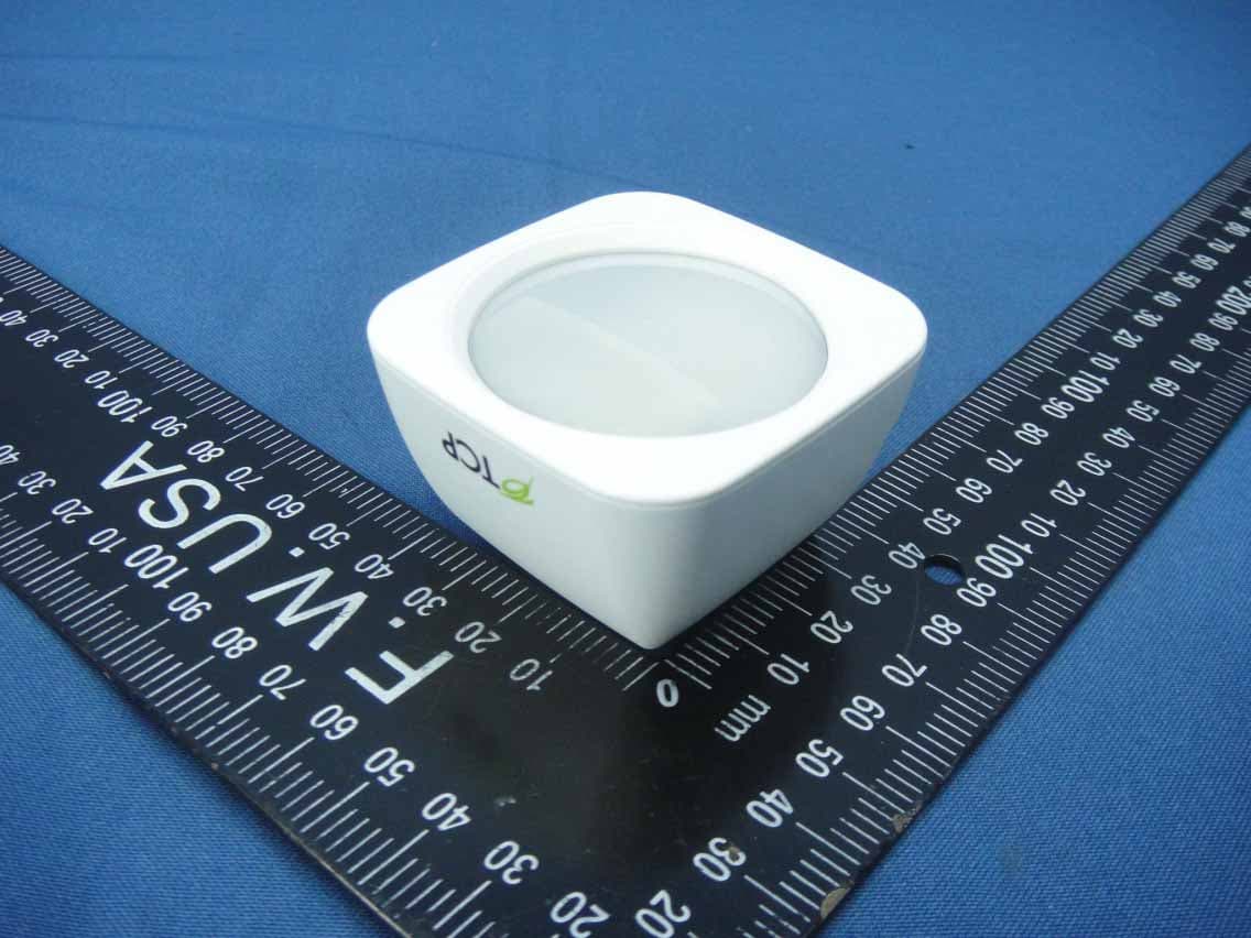
Z3M-GSYP1J11
Jul 14, 2014Wireless Motion Sensor
Equipment Class
DTS - Digital Transmission System
Z3M-ZBMOD1
Jan 16, 2014Zigbee Wireless Module
Equipment Class
DTS - Digital Transmission System
Z3M-JENMOD1
Jan 16, 2014Zigbee Wireless Module
Equipment Class
DTS - Digital Transmission System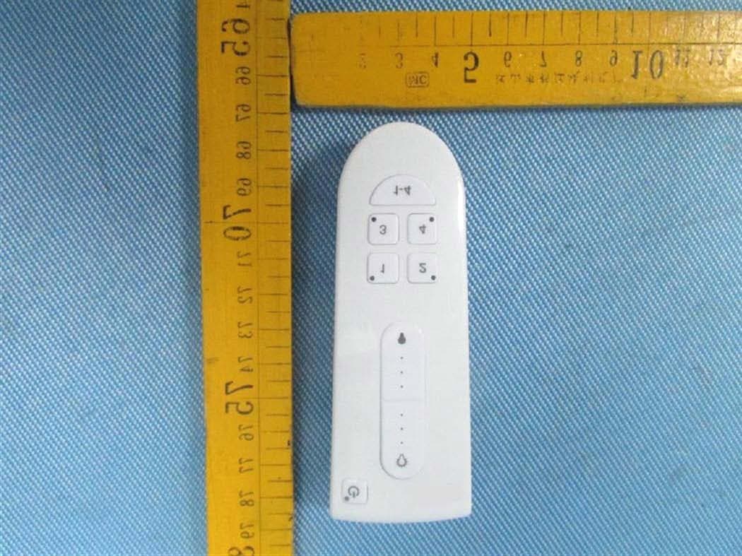
Z3M-GCM10
Feb 26, 2013LIGHTING CONTROLLER,JN,BUTTON,4CH
Equipment Class
DXX - Part 15 Low Power Communication Device Transmitter
Z3M-GLA19147IAJNW
Nov 18, 2012Self-Ballasted LED-lamps
Equipment Class
DXX - Part 15 Low Power Communication Device Transmitter