Z3M-GSYP1J11Wireless Motion Sensor
Greenwave Reality Inc. d/b/a Greenwave Systems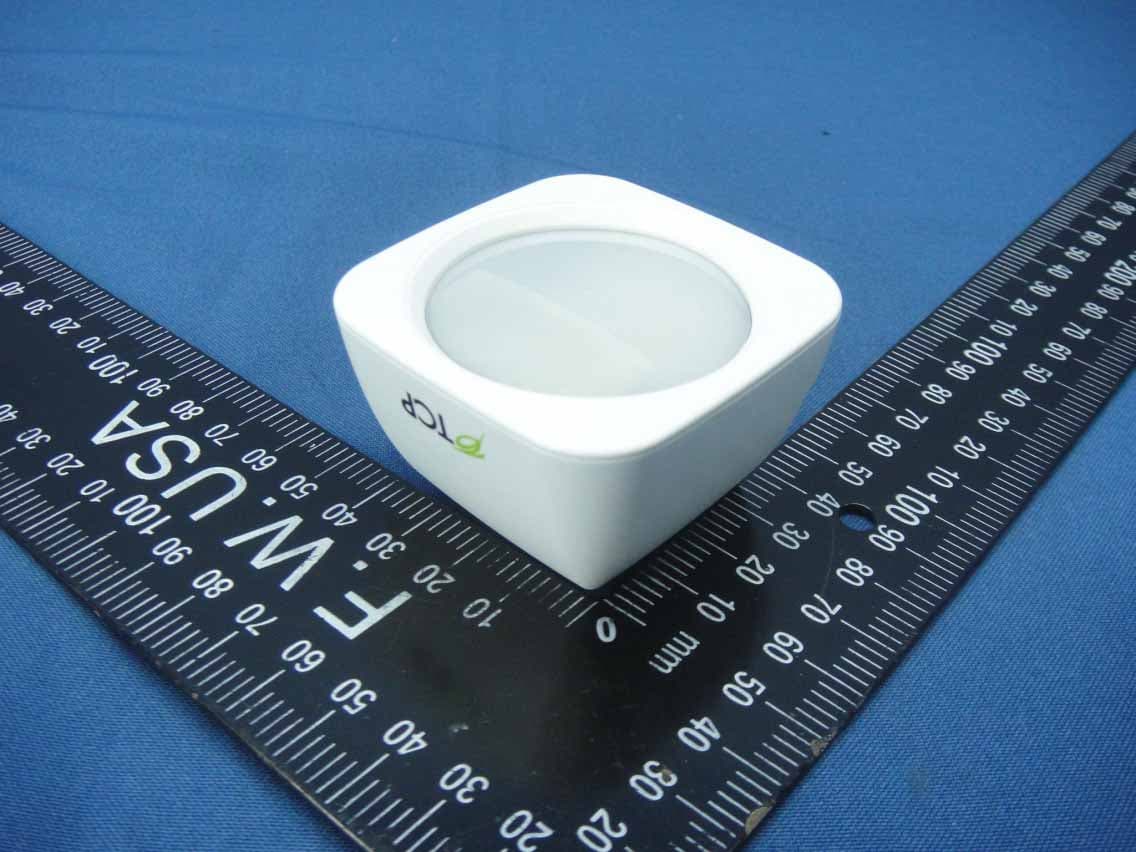
Click to zoom
Application Details
- Equipment Class
- DTS - Digital Transmission System
- Date of Grant
- Jul 14, 2014
- Application Purpose
- Original Equipment
- Date of Application
- Jul 14, 2014
- Equipment Note
- Wireless Motion Sensor
- Frequency Range
- 2405.00000000 - 2480.00000000
- Country
- United States
Documents & Files
Document Text
Text extracted from the exhibit documents filed with the FCC. Open a document above to read the original.
Users Manual
Amano Motion Sensor Wall Mount Instructions The sensor is attached to a wall or corner by means of a magnetic bracket, which allows easy adjustment of viewing direction (detection-coverage pattern) as well as easy dismounting for battery replacement. NOTE: Special optical design allows the sensor to detect minor body motions within a 16’ x 16’ area, and major body motions within a 20’ x 20’ area. In order to provide this performance, the sensor must be mounted on its standard bracket, within a one of two height ranges: 6’ 6”– 8’ 6” (2.0m – 2.6m) or 8’ 6”– 10’ 6” (2.6m – 3.2m) Preferred heights are: 7’ 6” (2.3m) and 10’ 0” (3m). Selecting mounting location and detection-coverage pattern: Basic rectangular-room application: The sensor “sees” within a 90° angle (+/- 45° left/right from its pointing direction (as shown in top view Figure 1a), via a total of 80 fields of view (“views”). These views aim both outward and downward from the sensor (6° to 54° or 11° to 59°) as shown in side view Figure 1b. Thus, an entire room (up to 20’ x 20’) can be covered by mounting the sensor in one corner, as shown in the plan view figure 2a. Occupancy is detected in response to radiant- temperature changes seen within a view, for example, when persons move into or out of a view. Figure 2a. Place sensor facing away from large windows. Figure 2b. Avoid sensor facing large windows. Orient the coverage-pattern views so that they don’t lead directly from the sensor to items such as: 1. Larger (street-facing) windows (Figure 2b) 2. Portable or wall-mounted heaters 3. People in adjacent rooms via doors wall openings. Figure 1b. Side view Sensor at 10° angle (See mounting proceedure.) Figure 1a. Plan (Top) view Sensor at 0° angle Sensor at 45° angle Sensor pointing direction FCC Interference Statement This device complies with Part 15 of the FCC Rules. Operation is subject to the following two conditions: (1) This device may not cause harmful interference, and (2) this device must accept any interference received, including interference that may cause undesired operation. This equipment has been tested and found to comply with the limits for a Class B digital device, pursuant to Part 15 of the FCC Rules. These limits are designed to provide reasonable protection against harmful interference in a residential installation. This equipment generates, uses and can radiate radio frequency energy and, if not installed and used in accordance with the instructions, may cause harmful interference to radio communications. However, there is no guarantee that interference will not occur in a particular installation. If this equipment does cause harmful interference to radio or television reception, which can be determined by turning the equipment off and on, the user is encouraged to try to correct the interference by one of the following measures: • Reorient or relocate the receiving antenna. • Increase the separation between the equipment and receiver. • Connect the equipment into an outlet on a circuit different from that to which the receiver is connected. • Consult the dealer or an experienced radio/TV technician for help. FCC Caution: Any changes or modifications not expressly approved by the party responsible for compliance could void the user's authority to operate this equipment. This transmitter must not be co-located or operating in conjunction with any other antenna or transmitter. Radiation Exposure Statement: This equipment complies with FCC radiation exposure limits set forth for an uncontrolled environment. This equipment should be installed and operated with minimum distance 20cm between the radiator and your body. Mounting height: Choose a mounting height between 6’ 6” and 10’ 6”. (Preferred heights are 7’ 6” and 10’ 0”.) Mounting procedure: The sensor’s bracket is mounted by two screws along a vertical line, as shown in figure 8 and figure 9, either on a flat wall or in a corner. Use the provided drill template, or mark two positions, 7/8” (22mm) apart, and drill two holes (xx if anchors are used, or yy if only screws will be used). Note that the bracket’s vertical angle is not 90°. According to the mounting height selected, orient the bracket sloping upward (number “5” up) or sloping downward (number “10” up). Figure 9 illustrates the bracket with the number “10” up. 6’ 6” – 8’ 6” 5 up (sensor facing downward at 5° angle) or 8’ 6” – 10’ 6” 10 up (sensor facing downward at 10° angle) Install the two screws to fasten the bracket. Install the wall-mount cover (figure 8) or the corner- mount cover (figure 9). Figure 6 shows the sensor rotated 45° on a flat-wall- mounted bracket to ignore motion within a non-entry walking route. Figure 7 shows a 20’ x 40’ room covered by 2 sensors. Figure 5 shows the coverage pattern with the sensor mounted and pointing straight outward in a 16’ x 32’ room. Coverage control for specific applications: In any mounting configuration, the sensor may be rotated in order to provide defined detection coverage. Several useful configurations are possible with the sensor mounted on a flat wall. Figure 3 shows a defined coverage/non-coverage pattern in a rectangular room, with the sensor rotated 45° on a flat-wall- mounted bracket. Figure 4 shows a different rotation position whereby the sensor will ignore a non- entry walking route. Figure 3. Figure 5.Figure 6. Figure 7. Figure 8. Figure 9. Figure 4. 90 ̊ Industry Canada Statement: This device complies with RSS-210 of the Industry Canada Rules. Operation is subject to the following two conditions: (1) This device may not cause harmful interference, and (2) this device must accept any interference received, including interference that may cause undesired operation. Ce dispositif est conforme à la norme CNR-210 d'Industrie Canada applicable aux appareils radio exempts de licence. Son fonctionnement est sujet aux deux conditions suivantes: (1) le dispositif ne doit pas produire de brouillage préjudiciable, et (2) ce dispositif doit accepter …
Text truncated - open the document above for the full version.
External Photos
Report No.: 140605E05 Page 1 CONSTRUCTION PHOTOS OF EUT
ID Label/Location Info
LABEL LOCATION FCC ID: Z3M-GSYP1J11 REVAPPROVEDDATE REV SIZE DWG TITLE DWG NO. SCALESHEET REV A4A4 B 1/1 1 OF 1 SANDY CHEN CIHYI CHIU CIHYI CHIU 04/08/14 04/08/14 04/08/14 04/08/14 SANDY CHEN 4L-YMS1107-001AB RELEASE TO FILE 06/17/14 SANDY CHEN B DESCRIPTION REVISIONS PART NUMBER BLOCK PART NUMBER WNC PROPRIETARY YMS1-GR 20 Park Avenue II, Hsinchu Science Park, Hsinchu 308, Taiwan, R.O.C. Tel: 886-3-6667799 Fax: 886-3-5788726 4L-YMS1107-001 LABEL, PRODUCT, 27.6X31.4/C2.0/R0.5, YMS1-GR NOTES: 1. MATERIAL: WHITE PET, t=0.05 ADHESIVE: 網紋背膠, t=0.024 2. COLOR: 底色為材質原色 3. TEMPERATURE RESISTANT= 80 0 C 4. 捲狀出貨 5. 被貼物:塑膠殼(彎曲面) R0.5, 2PLS C2.0 31.4 27.6 RED: on line print CURVED CR123-A MADE IN CHINA FCC ID: Z3M-GSYP1J11 IC: 10257A-SYP1J1100 SYP1-J11YY-XX Model no. 16Y1-XXXX-XXXXX Ser. no. Wireless Motion Sensor CR123-A MADE IN CHINA FCC ID: Z3M-GSYP1J11 IC: 10257A-SYP1J1100 Wireless Motion Sensor CR123-A MADE IN CHINA FCC ID: Z3M-GSYP1J11 IC: 10257A-SYP1J1100 Wireless Motion Sensor
Internal Photos
Report No.: 140605E05 Page 1 CONSTRUCTION PHOTOS OF EUT Report No.: 140605E05 Page 2
RF Exposure Info
Report No.: SA140605E05 1 of 6 Report Format Version 5.0.0 RF EXPOSURE REPORT REPORT NO.: SA140605E05 MODEL NO.: SYP1-J1100-GR, SYP1-J11YY-XX (YY-Colour Variant (0~9 and A~Z) and XX-Customer Variant (0~9 and A~Z)) FCC ID: Z3M-GSYP1J11 RECEIVED: June 05, 2014 TESTED: June 18, 2014 ISSUED: July 04, 2014 APPLICANT: Greenwave Systems Pte Ltd ADDRESS: 41 Science Park Road, #03-01, The Gemini, Science Park II, Singapore, 117610 Singapore ISSUED BY: Bureau Veritas Consumer Products Services (H.K.) Ltd., Taoyuan Branch Hsin Chu Laboratory LAB ADDRESS: No. 81-1, Lu Liao Keng, 9th Ling,Wu Lung Tsuen, Chiung Lin Hsiang, Hsin Chu Hsien 307, Taiwan, R.O.C. This report should not be used by the client to claim product certification, approval, or endorsement by any government agencies. This report is for your exclusive use. Any copying or replication of this report to or for any other person or entity, or use of our name or trademark, is permitted only with our prior written permission. This report sets forth our findings solely with respect to the test samples identified herein. The results set forth in this report are not indicative or representative of the quality or characteristics of the lot from which a test sample was taken or any similar or identical product unless specifically and expressly noted. Our report includes all of the tests requested by you and the results thereof based upon the information that you provided to us. You have 60 days from date of issuance of this report to notify us of any material error or omission caused by our negligence, provided, however, that such notice shall be in writing and shall specifically address the issue you wish to raise. A failure to raise such issue within the prescribed time shall constitute your unqualified acceptance of the completeness of this report, the tests conducted and the correctness of the report contents. Unless specific mention, the uncertainty of measurement has been explicitly taken into account to declare the compliance or non-compliance to the specification Report No.: SA140605E05 2 of 6 Report Format Version 5.0.0 TABLE OF CONTENTS RELEASE CONTROL RECORD ..................................................................................... 3 1. CERTIFICATION ...................................................................................................... 4 2. RF EXPOSURE LIMIT ............................................................................................. 5 3. MPE CALCULATION FORMULA ............................................................................. 5 4. CLASSIFICATION .................................................................................................... 5 5. ANTENNA GAIN ...................................................................................................... 5 6. CALCULATION RESULT OF MAXIMUM CONDUCTED POWER .......................... 6 Report No.: SA140605E05 3 of 6 Report Format Version 5.0.0 RELEASE CONTROL RECORD ISSUE NO. REASON FOR CHANGE DATE ISSUED SA140605E05 Original release July 04, 2014 Report No.: SA140605E05 5 of 6 Report Format Version 5.0.0 2. RF EXPOSURE LIMIT LIMITS FOR MAXIMUM PERMISSIBLE EXPOSURE (MPE) FREQUENCY RANGE (MHz) ELECTRIC FIELD STRENGTH (V/m) MAGNETIC FIELD STRENGTH (A/m) POWER DENSITY (mW/cm 2 ) AVERAGE TIME (minutes) LIMITS FOR GENERAL POPULATION / UNCONTROLLED EXPOSURE 300-1500 ... ... F/1500 30 1500-100,000 ... ... 1.0 30 F = Frequency in MHz 3. MPE CALCULATION FORMULA Pd = (Pout*G) / (4*pi*r 2 ) where Pd = power density in mW/cm 2 Pout = output power to antenna in mW G = gain of antenna in linear scale pi = 3.1416 r = distance between observation point and center of the radiator in cm 4. CLASSIFICATION The antenna of this product, under normal use condition, is at least 20cm away from the body of the user. So, this device is classified as Mobile Device. 5. ANTENNA GAIN The antenna provided to the EUT, please refer to the following table: Brand Antenna Type Antenna Connector Gain(dBi) Frequency range (GHz) NA PCB NA 1.2 2.4~2.4835 Report No.: SA140605E05 6 of 6 Report Format Version 5.0.0 6. CALCULATION RESULT OF MAXIMUM CONDUCTED POWER For Zigbee FREQUENCY BAND (MHz) CONDUCTED POWER (mW) ANTENNA GAIN (dBi) DISTANCE (cm) POWER DENSITY (mW/cm 2 ) LIMIT (mW/cm 2 ) 2405 - 2480 1.694 1.2 20 0.00044 1.00 --- END --- CONCLUSION: Both of the WLAN and Zigbee can transmit simultaneously, the formula of calculated the MPE is: CPD 1 / LPD 1 + CPD 2 / LPD 2 + ......etc. < 1 CPD = Calculation power density LPD = Limit of power density Therefore, the worst-case situation is 0.10417 / 1 + 0.00367 / 1= 0.108, which is less than “1”. This confirmed that the device comply with FCC 1.1310 MPE limit.
Test Report
Report No.: RF140605E05 1 of 34 Report Format Version 5.2.0 FCC TEST REPORT REPORT NO.: RF140605E05 MODEL NO.: SYP1-J1100-GR, SYP1-J11YY-XX (YY-Colour Variant (0~9 and A~Z) and XX-Customer Variant (0~9 and A~Z)) FCC ID: Z3M-GSYP1J11 RECEIVED: June 05, 2014 TESTED: June 10 to 18, 2014 ISSUED: July 04, 2014 APPLICANT: Greenwave Systems Pte Ltd ADDRESS: 41 Science Park Road, #03-01, The Gemini, Science Park II, Singapore, 117610 Singapore ISSUED BY: Bureau Veritas Consumer Products Services (H.K.) Ltd., Taoyuan Branch Hsin Chu Laboratory LAB ADDRESS : No. 81-1, Lu Liao Keng, 9th Ling, Wu Lung Tsuen, Chiung Lin Hsiang, Hsin Chu Hsien 307, Taiwan, R.O.C. TEST LOCATION (1): No. 81-1, Lu Liao Keng, 9th Ling, Wu Lung Tsuen, Chiung Lin Hsiang, Hsin Chu Hsien 307, Taiwan, R.O.C. TEST LOCATION (2): No. 49, Ln. 206, Wende Rd., Shangshan Tsuen, Chiung Lin Hsiang, Hsin Chu Hsien 307, Taiwan, R.O.C. This report should not be used by the client to claim product certification, approval, or endorsement by TAF or any government agencies. This report is for your exclusive use. Any copying or replication of this report to or for any other person or entity, or use of our name or trademark, is permitted only with our prior written permission. This report sets forth our findings solely with respect to the test samples identified herein. The results set forth in this report are not indicative or representative of the quality or characteristics of the lot from which a test sample was taken or any similar or identical product unless specifically and expressly noted. Our report includes all of the tests requested by you and the results thereof based upon the information that you provided to us. You have 60 days from date of issuance of this report to notify us of any material error or omission caused by our negligence, provided, however, that such notice shall be in writing and shall specifically address the issue you wish to raise. A failure to raise such issue within the prescribed time shall constitute your unqualified acceptance of the completeness of this report, the tests conducted and the correctness of the report contents. Unless specific mention, the uncertainty of measurement has been explicitly taken into account to declare the compliance or non-compliance to the specification Report No.: RF140605E05 2 of 34 Report Format Version 5.2.0 Table of Contents RELEASE CONTROL RECORD .......................................................................................... 4 1. CERTIFICATION ...................................................................................................... 5 2. SUMMARY OF TEST RESULTS .............................................................................. 6 2.1 MEASUREMENT UNCERTAINTY ........................................................................... 7 3. GENERAL INFORMATION ....................................................................................... 8 3.1 GENERAL DESCRIPTION OF EUT ......................................................................... 8 3.2 DESCRIPTION OF TEST MODES ........................................................................... 9 3.2.1 TEST MODE APPLICABILITY AND TESTED CHANNEL DETAIL ......................... 10 3.3 GENERAL DESCRIPTION OF APPLIED STANDARDS ........................................ 12 3.4 DUTY CYCLE OF TEST SIGNAL ........................................................................... 13 3.5 DESCRIPTION OF SUPPORT UNITS ................................................................... 14 3.6 CONFIGURATION OF SYSTEM UNDER TEST .................................................... 14 4. TEST TYPES AND RESULTS ................................................................................ 15 4.1 RADIATED EMISSION AND BANDEDGE MEASUREMENT ................................. 15 4.1.1 LIMITS OF RADIATED EMISSION AND BANDEDGE MEASUREMENT .............. 15 4.1.2 TEST INSTRUMENTS ........................................................................................... 16 4.1.3 TEST PROCEDURES ............................................................................................ 17 4.1.4 DEVIATION FROM TEST STANDARD .................................................................. 17 4.1.5 TEST SETUP ......................................................................................................... 18 4.1.6 EUT OPERATING CONDITIONS ........................................................................... 18 4.1.7 TEST RESULTS ..................................................................................................... 19 4.2 6DB BANDWIDTH MEASUREMENT ..................................................................... 23 4.2.1 LIMITS OF 6DB BANDWIDTH MEASUREMENT .................................................. 23 4.2.2 TEST INSTRUMENTS ........................................................................................... 23 4.2.3 TEST PROCEDURE .............................................................................................. 23 4.2.4 DEVIATION FROM TEST STANDARD .................................................................. 23 4.2.5 TEST SETUP ......................................................................................................... 23 4.2.6 EUT OPERATING CONDITIONS ........................................................................... 23 4.2.7 TEST RESULTS ..................................................................................................... 24 4.3 CONDUCTED OUTPUT POWER MEASUREMENT ............................................. 25 4.3.1 LIMITS OF CONDUCTED OUTPUT POWER MEASUREMENT ........................... 25 4.3.2 TEST INSTRUMENTS ........................................................................................... 25 4.3.3 TEST PROCEDURES ............................................................................................ 25 4.3.4 DEVIATION FROM TEST STANDARD .............................................…
Text truncated - open the document above for the full version.
Test Setup Photos
Report No.: 140605E05 Page 1 Reference No.: PHOTOGRAPHS OF THE TEST CONFIGURATION RADIATED EMISSION TEST (Below 1GHz) Report No.: 140605E05 Page 2 Reference No.: Report No.: 140605E05 Page 3 Reference No.: RADIATED EMISSION TEST (Above 1GHz) Report No.: 140605E05 Page 4 Reference No.:
Contact Information
Applicant
Troy Pliska(Executive VP of Operations)
Test Firm
Bureau Veritas CPS (H.K.) Ltd., Taoyuan BranchRichard Chen
Technical Specifications
| # | Rule Parts | Frequency Range | Power Output |
|---|---|---|---|
| 1 | 15C | 2.40 GHz - 2.48 GHz | 2.00 mW |
Other Applications from Greenwave Reality Inc. d/b/a Greenwave Systems

Z3M-GUBW1J1
Apr 28, 2014Lighting Gateway
Equipment Class
DTS - Digital Transmission System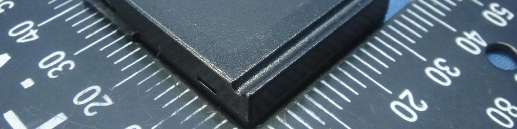
Z3M-ZBMOD1
Jan 16, 2014Zigbee Wireless Module
Equipment Class
DTS - Digital Transmission System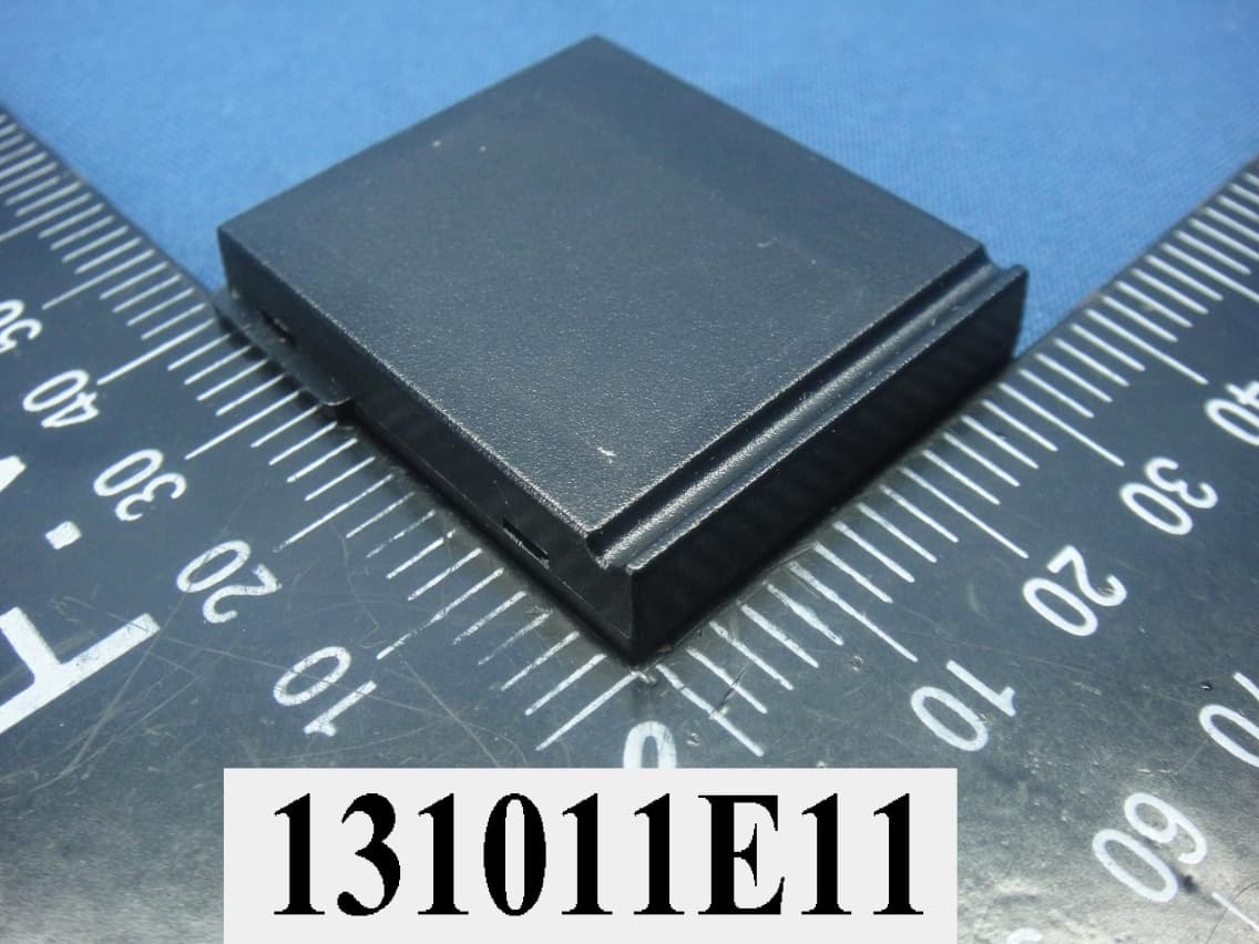
Z3M-JENMOD1
Jan 16, 2014Zigbee Wireless Module
Equipment Class
DTS - Digital Transmission System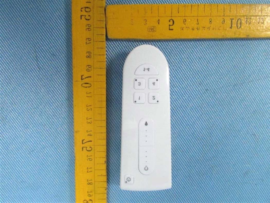
Z3M-GCM10
Feb 26, 2013LIGHTING CONTROLLER,JN,BUTTON,4CH
Equipment Class
DXX - Part 15 Low Power Communication Device Transmitter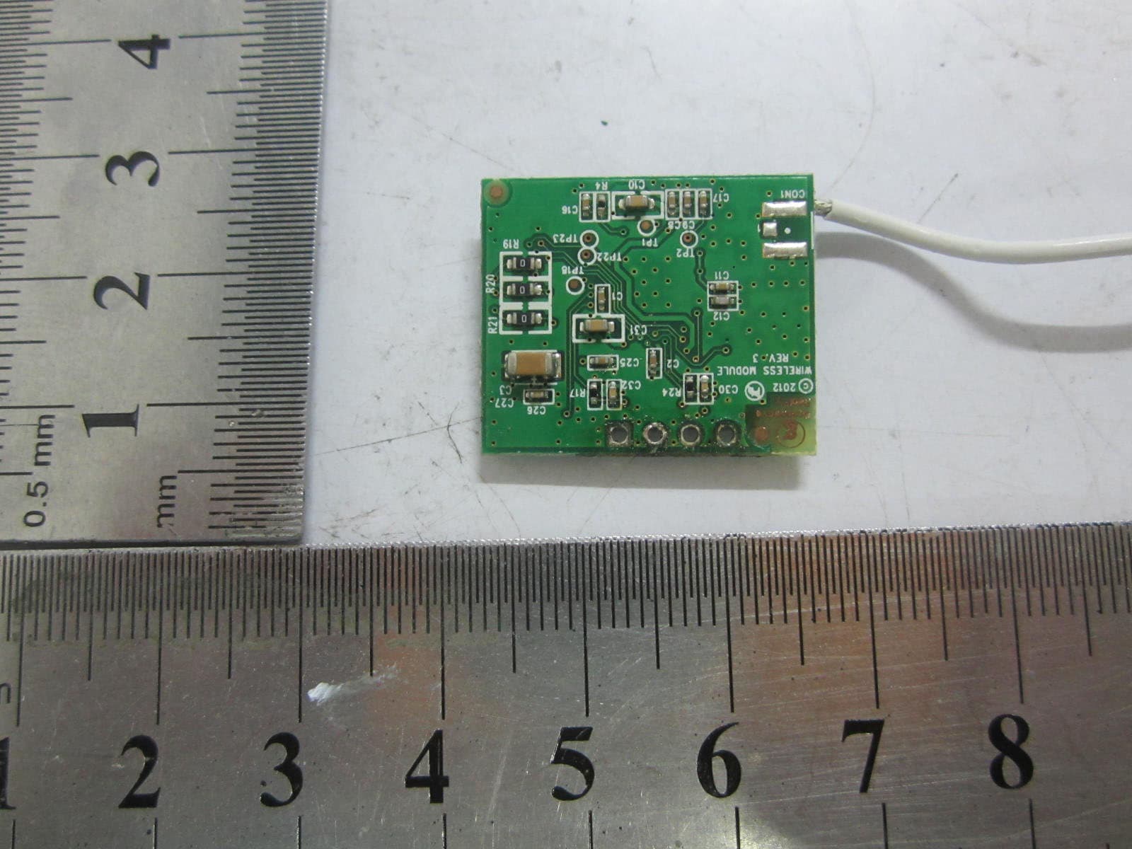
Z3M-GLA19147IAJNW
Nov 18, 2012Self-Ballasted LED-lamps
Equipment Class
DXX - Part 15 Low Power Communication Device Transmitter