Z3M-GLA19147IAJNWSelf-Ballasted LED-lamps
Greenwave Reality Inc. d/b/a Greenwave Systems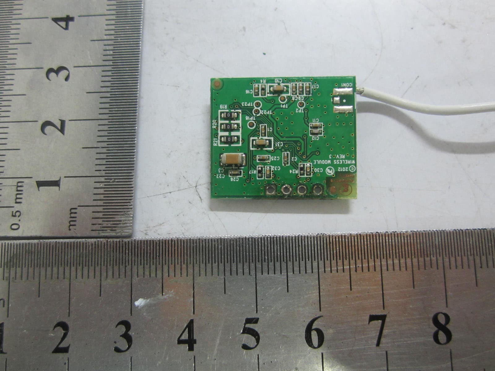
Click to zoom
Application Details
- Equipment Class
- DXX - Part 15 Low Power Communication Device Transmitter
- Date of Grant
- Nov 18, 2012
- Application Purpose
- Original Equipment
- Date of Application
- Oct 22, 2012
- Equipment Note
- Self-Ballasted LED-lamps
- Frequency Range
- 2405.00000000 - 2480.00000000
- Country
- United States
Documents & Files
Document Text
Text extracted from the exhibit documents filed with the FCC. Open a document above to read the original.
Users Manual
LED-lamps 2 • The light bulb includes wireless technology that allows the light bulb to connect to a network and be managed remotely. Because the light bulbs can be connected to a network, you have greater flexibility in how you use them. For example, you can program your lighting network so that when you press a button upon arriving home, an entryway and a hallway light turn on. Or when you go to bed, your remote control can turn off all lights on the network. Planning Your Lighting Network Whether you have only one wireless light bulb or you are replacing your entire home with wireless light bulbs, you should plan how you want the lighting on your network to behave. For example, if you only have one light bulb you might want to place it in a central location that would be optimum for turning on and off when you are away or arrive home. If you have multiple light bulbs, however, you might want to set them up in lighting groups to be able to better manage them across your home. Note: Light fixtures that have dimmer controls are not recommended for your network light bulbs. However, they can be used if the dimmer level is set to 100%. 3 Lighting Groups A lighting group is a set of network light bulbs that you can control together through your remote control. For example, you might have a lighting group that includes light bulbs on the same floor. Or you might have a group that includes hallway and entryway lights, making it easy to turn on or off as you arrive or leave home. All light bulbs in the same group turn on and off together and brighten or dim to the same level. The following limitations apply when working with network light bulbs and lighting groups in a system using remote control only: • One light bulb can belong to only one lighting group. • One remote control can control up to four different lighting groups. • One lighting group can contain up to 40 light bulbs (the maximum light bulbs allowed in a remote control only network). Note: By default, each light bulb in your lighting kit is pre-assigned to a lighting group. Numbering on the lighting kit package shows the lighting group to which each light bulb is assigned. Multi-fixture Lights When installing light bulbs or setting up lighting groups, you should consider how you want multi-fixture lights to behave. Since power to the light has to remain on (so the remote control can access the light bulb) you would use either all network light bulbs in a multi-fixture light or no network light bulbs at all. If you are using network light bulbs in a multi-fixture light, you should add them all to the same lighting group so that they turn on and off together (though you do not have to). 4 Network Range As with any remote control, your lighting kit’s remote control must be within range of your lighting network to be able to control your lighting. However, this does not mean that it has to be within range of all network light bulbs. Since the light bulbs are interconnected across the network, they can pass commands to each other as long as they are within network range of each other. This means that a nearby light bulb can receive your remote control command and pass that command across the network of connected light bulbs, ultimately to a light bulb you want to control in a distant room. Because of this effect, larger homes would make better use of having more network light bulbs spread across the home, maintaining a distance that allows each light bulb to communicate with one another. Maximum Number of Light Bulbs You can install up to 40 light bulbs on the same network to work with your remote control. Note: Networks that use a Lighting Gateway can hold more light bulbs. If you are interested in upgrading, you should refer to the Optional Lighting Gateway chapter for more information about its features. Power Failure with Wireless Light Bulbs Wireless light bulbs are powered through light fixtures the same way standard light bulbs are. However, you must leave the light fixtures in the on position so that power is available when using your remote control to turn the wireless light bulbs on and off. If power is removed from a light bulb, whether from power failure or from manually 8 Installation Installation of your lighting kit includes installing the light bulbs into light fixtures and preparing the remote control. Installation Steps Before installing the light bulbs, determine the appropriate locations in your home for installing them. The Lighting Kit Overview chapter provides information on planning your lighting network. When you are ready to install the light bulbs, perform the following steps: 1. Turn power OFF to the light fixtures where you will be installing the network light bulbs. 2. Remove any existing light bulbs from the light fixtures. 3. Install each network light bulb into the light fixtures as you would any standard light bulb. When removing each light bulb from the package, note the pre-assigned lighting group number on the package and install the bulbs in the light fixtures based on your lighting group plan. 4. Turn power on to the light fixtures. The light bulbs turn on to full brightness. If a light fixture has a dimmer control (not recommended), set the dimmer level to full brightness. 9 5. Remove the battery compartment cover from the back of the remote control, and insert two AA alkaline batteries (included). The first time you insert batteries, the primary LED light flashes while the remote control determines the best signal for your lighting system. When this process is complete, the LED light will remain on for approximately five seconds. When the LED light turns off, your remote control is ready. Note that this process occurs only during initial battery installation and does not occur when you replace batteries in the future unless a factory reset is performed. 6. Leave the light fixture switches ON so that power is available when using your remote control to turn the light bulbs on and off. Once these …
Text truncated - open the document above for the full version.
Block Diagram
LED driver AC input Wireless Module (Oscillator freq: 32 MHz) LED light source D C S u p p l y C o n t r o l Antenna Connected Light Device Block Diagram Model: LA191-0470IA-JNW1 FCC ID: Z3M-GLA19147IAJNW
Internal Photos
Greenwave Reality Pte Ltd Model: LA191-0470IA-JNW1 REPORT NO.: STR12108216I FCC PART 15.249 EXHIBIT 3 - EUT INTERNAL PHOTOGRAPHS EUT Housing and Board View 1 EUT Housing and Board View 2 Greenwave Reality Pte Ltd Model: LA191-0470IA-JNW1 REPORT NO.: STR12108216I FCC PART 15.249 Solder Board-Component View 1 Solder Board-Component View 2 Greenwave Reality Pte Ltd Model: LA191-0470IA-JNW1 REPORT NO.: STR12108216I FCC PART 15.249 Solder Board-Component View 3 Solder Board-Component View 4 Greenwave Reality Pte Ltd Model: LA191-0470IA-JNW1 REPORT NO.: STR12108216I FCC PART 15.249 Solder Board-Component View 5 Antenna View Ant. 2405~2480MHz
Operational Description
Operational Description 1. The LED driver circuit provide AC/DC conversion and 2 DCoutput. One is for the LED light source and other for the wireless module. 2. The wireless module is based on a single chip RF SoC JN5142. It is based on IEEE802.15.4 operating at 2.4GHz, and the frequency range is 2405MHz~2480MHz. Maximum field strength is 85.25dBuV/m at 3m distance, is GFSK modulation. 3. JN5142 oprates with a 32MHz crystal. It has built in RF output which connects to Antenna via the matching circuits, and the Antenna Gain is 0 dBi.
Test Report
Greenwave Reality Pte Ltd Model: LA191-0470IA-JNW1 REPORT NO.: STR12108216I PAGE 1 OF 27 FCC PART 15.249 FCC Part 15C Measurement and Test Report For Greenwave Reality Pte Ltd 41 Science Park Road, #03-01, The Gemini, Science Park II, FCC ID: Z3M-GLA19147IAJNW FCC Rules: FCC Part 15.249 Product Description: Self-Ballasted LED-lamps Tested Model: LA191-0470IA-JNW1 Report No.: STR12108216I Tested Date: 2012-10-25 to 2012-10-29 Issued Date: 2012-10-30 Tested By: Jack Li / Engineer Reviewed By: Lahm Peng / EMC Manager Approved & Authorized By: Jandy so / PSQ Manager Prepared By: SEM.Test Compliance Service Co., Ltd 3/F, Jinbao Commerce Building, Xin'an Fanshen Road, Bao'an District, Shenzhen, P.R.C.(518101) Tel.: +86-755-33663308 Fax.: +86-755-33663309 Website: www.semtest.com.cn Note: This test report is limited to the above client company and the product model only. It may not be duplicated without prior permitted by SEM.Test Compliance Service Co., Ltd Greenwave Reality Pte Ltd Model: LA191-0470IA-JNW1 REPORT NO.: STR12108216I PAGE 2 OF 27 FCC PART 15.249 TABLE OF CONTENTS 1. GENERAL INFORMATION ...................................................................................................................................3 1.1 PRODUCT DESCRIPTION FOR EQUIPMENT UNDER TEST (EUT)...............................................................................3 1.2 TEST STANDARDS...................................................................................................................................................4 1.3 TEST METHODOLOGY.............................................................................................................................................4 1.4 TEST FACILITY.......................................................................................................................................................4 1.5 EUT SETUP AND TEST MODE.................................................................................................................................5 2. SUMMARY OF TEST RESULTS ...........................................................................................................................6 3. ANTENNA REQUIREMENTS................................................................................................................................7 3.1 STANDARD APPLICABLE.........................................................................................................................................7 3.2 TEST RESULT..........................................................................................................................................................7 4. RADIATED EMISSIONS .........................................................................................................................................8 4.1 MEASUREMENT UNCERTAINTY..............................................................................................................................8 4.2 STANDARD APPLICABLE.........................................................................................................................................8 4.3 TEST EQUIPMENT LIST AND DETAILS.....................................................................................................................8 4.4 TEST PROCEDURE...................................................................................................................................................9 4.5 CORRECTED AMPLITUDE & MARGIN CALCULATION..............................................................................................9 4.6 ENVIRONMENTAL CONDITIONS..............................................................................................................................9 4.7 SUMMARY OF TEST RESULTS/PLOTS....................................................................................................................10 5. OUT OF BAND EMISSIONS.................................................................................................................................18 5.1 STANDARD APPLICABLE.......................................................................................................................................18 5.2 TEST EQUIPMENT LIST AND DETAILS...................................................................................................................18 5.3 TEST PROCEDURE.................................................................................................................................................18 5.4 ENVIRONMENTAL CONDITIONS............................................................................................................................18 5.5 SUMMARY OF TEST RESULTS/PLOTS....................................................................................................................18 6. EMISSION BANDWIDTH .....................................................................................................................................21 6.1 STANDARD APPLICABLE.......................................................................................................................................21 6.2 TEST EQUIPMENT LIST AND DETAILS...................................................................................................................21 6.3 TEST PROCEDURE.................................................................................................................................................21 6.4 ENVIRONMENTAL CONDITIONS............................................................................................................................21 6.5 SUMMARY OF TEST RESULTS/PLOTS....................................................................................................................21 7. CONDUCTED EMISSIONS ..................................................................................................................................24 7.1 MEASUREMENT UNCERTAINTY......…
Text truncated - open the document above for the full version.
Test Setup Photos
Greenwave Reality Pte Ltd Model: LA191-0470IA-JNW1 REPORT NO.: STR12108216I FCC PART 15.249 EXHIBIT 4 - TEST SETUP PHOTOGRAPHS Conducted Emission Test Setup Radiation Emission Test Setup (9kHz to 30MHz) Greenwave Reality Pte Ltd Model: LA191-0470IA-JNW1 REPORT NO.: STR12108216I FCC PART 15.249 Radiation Emission Test Setup (30MHz to 1GHz) Radiation Emission Test Setup (Above 1GHz)
Contact Information
Applicant
Troy Pliska(Executive VP of Operations)
Test Firm
SEM.Test Compliance Service Co., Ltd.Jandy So
Technical Specifications
| # | Rule Parts | Frequency Range | Power Output |
|---|---|---|---|
| 1 | 15C | 2.40 GHz - 2.48 GHz | - |
Other Applications from Greenwave Reality Inc. d/b/a Greenwave Systems
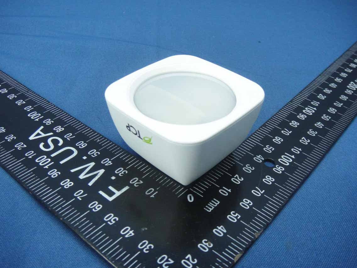
Z3M-GSYP1J11
Jul 14, 2014Wireless Motion Sensor
Equipment Class
DTS - Digital Transmission System
Z3M-GUBW1J1
Apr 28, 2014Lighting Gateway
Equipment Class
DTS - Digital Transmission System
Z3M-ZBMOD1
Jan 16, 2014Zigbee Wireless Module
Equipment Class
DTS - Digital Transmission System
Z3M-JENMOD1
Jan 16, 2014Zigbee Wireless Module
Equipment Class
DTS - Digital Transmission System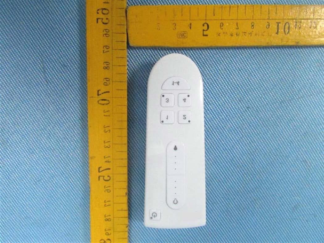
Z3M-GCM10
Feb 26, 2013LIGHTING CONTROLLER,JN,BUTTON,4CH
Equipment Class
DXX - Part 15 Low Power Communication Device Transmitter