Z3M-JENMOD1Zigbee Wireless Module
Greenwave Reality Inc. d/b/a Greenwave Systems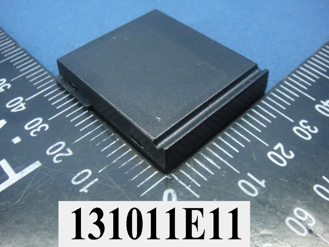
Click to zoom
Application Details
- Equipment Class
- DTS - Digital Transmission System
- Date of Grant
- Jan 16, 2014
- Application Purpose
- Original Equipment
- Date of Application
- Jan 16, 2014
- Equipment Note
- Zigbee Wireless Module
- Frequency Range
- 2405.00000000 - 2480.00000000
- Country
- United States
Documents & Files
Document Text
Text extracted from the exhibit documents filed with the FCC. Open a document above to read the original.
Users Manual
JENNIC WIRELESS MODULE User Guide Model FiOSJenMod1 Contents Chapter 1 Introduction ...................................................................... 3 Purpose ........................................................................................................................... 3 Chapter 2 Frequently Asked Questions .......................................... 3 Chapter 3 Installing the JENNIC HAN module ................................ 4 Pre-requisites .................................................................................................................. 4 Step by Step Guide ......................................................................................................... 7 Step 1. Remove the HAN module port cover ................................................. 7 Step 2. Insert the HAN module. ..................................................................... 8 Step 3. Wait for notification to appear or enter HAN settings menu. .............. 9 Step 4. Finish installation ............................................................................... 9 Chapter 4 Connecting Devices to your SmartCloud .................... 10 TBD ............................................................................................................................... 10 Chapter 5 Notices and declarations .............................................. 11 Federal Communication Commission Interference Statement .................................... 11 Chapter 1 Introduction Purpose The (FiOS-JenMod1) HAN module is a plug-in JENNIC controller for your FiOS- BHR4 Gateway. It has an integrated antenna and is all you need for enabling your Gateway to connect your SmartCloud system to supported JENNIC home automation devices such as Motion Sensors, Thermostats, Alarm systems, Smart lights and more. More than 100 JENNIC Devices can be connected simultaneously through this module. Different types of HAN modules exist for connecting your SmartCloud solution to other types of networks such as JenNet-IP or Wireless M-bus. Chapter 2 Frequently Asked Questions Q: What Devices are supported? A: Many but not all JENNIC Devices are supported. Please visit our website (URL here) to see the up-to-date list of supported Devices that can be connected to your SmartCloud solution. Q: What can supported Devices be used for? A: That depends! Different kinds of Devices have different functions and purposes. A Motion Sensor for example is an "input" Device : It doesn't physically "do" anything except "detect" motion and provide that detection as an information signal to the rest of your SmartCloud system( and any Applications that you may have installed.) There are many other kinds of sensors that detect or measure different physical qualities such as humidity or temperature, or whether for example a door or window has been left open. Other kinds of Devices are not sensors at all - they don't measure anything. Instead they "do" things to affect their environment in different ways. Examples includes lamps and light bulbs (can turn light on and off), motorized blinds and windows (opens and closes), air conditioners or furnaces (cools and heats). The SmartCloud system lets you connect and control all these kinds of devices and configure automatic linkages that for example reacts intelligently in response to a signal - e.g. turn the lights in a room on when a motion sensor detects that someone is present. Chapter 3 Installing the JENNIC HAN module Pre‐requisites Verify that you have everything you need: The HAN module The FiOS-BHR4 Gateway It must be powered on, connected to the network and operating normally. An open slot for the HAN module on the backside of the FiOS-BHR4 If another module has been already installed, then it must be removed before you can install the JENNIC HAN module. Please refer to (chapter) for module un- installation instructions. You must be logged in to your home FiOS-BHR4 Gateway as Administrator You can use either the web app or the MyFiOS App (please consult the manual for your Gateway). You must have administrator login privileges. To verify that it is connected, open the app, select Settings Menu (the gear icon), "Gateway Status" and wait for the Status Screen to load. It should take only a few seconds. If it loads that means the Gateway is connected. Confirm that no red tags are showing. All green means you can continue with the installation. Step by Step Guide Step 1. Remove the HAN module port cover Use a fingernail or a flat-headed screwdriver. Step 2. Insert the HAN module. It can only go in with one orientation. It should slide in and come to a smooth stop with only the extraction finger handle protruding. If the module doesn't slide in very easy then verify that you have it the right way up. The HAN module label faces to the RIGHT when you watch the FiOS-BHR4 gateway from behind. Step 3. Wait for notification to appear or enter HAN settings menu. If you are using the MyFiOS app, a few seconds after you insert the Module you should receive a Notification that the HAN module has been inserted. Hit "OK" to continue. Otherwise, from the App home screen, hit the "gear" icon to bring up the Settings Menu. Choose "Home Automation Networks". From here you should now see the list of networks connected to the system. One of the entries should be named "JENNIC HAN" - tagged with the label "new". Hit it to continue. If the network has not showed up then please remove the HAN module from the port and go back to step 2 and try again. Step 4. Finish installation From the JENNIC HAN network screen, optionally change the name of the network in case you have more than one JENNIC network in your system and want to be able to distinguish them. In most circumstances you are now done with the HAN module setup and can now begin adding Devices to your JENNIC network: see (chapter name). Chapter 4 Connecting Devices to your SmartCloud TBD Chapter 5 Notices and declarations Federal Communic…
Text truncated - open the document above for the full version.
Cover Letter(s)
FCC ID: Z3M-JENMOD1 Report No.: RF130927E08C Modular Approval Request Letter Bureau Veritas Consumer Products Services (H.K.) Ltd., Taoyuan Branch December 24, 2013 Dear Application Examiner, Greenwave Reality Pte Ltd., Zigbee Wireless Module, FCC ID: Z3M-JENMOD1, would like to have your authorization as a modular approval specific to the mobile RF exposure condition. The requirements of Public Notice DA00-1407 have been met and shown on the following statements. 1. “The modular transmitter must have its own RF shielding.” The radio portion of this module has been shielded, please see exhibition External Photo. 2. “The modular transmitter must have buffered modulation/data inputs.” The EUT has buffered data inputs, it is integrated in chip JN5168. 3. “The modular transmitter must have its own power supply regulation.” The part number of this regulator is JN5168. 4. “The modular transmitter must comply with the antenna requirements of section 15.203 and 15.204(C).” The EUT meets the FCC antenna requirements. The spurious emission, unique antenna connector and photo of antennas are shown in the test report. 5. “The modular transmitter must be tested in a stand-alone configuration” The EUT was tested in a stand-alone configuration via a USB extender. Please see section Photographs of Test Configuration in the test report, the EUT was plugged in this extender. 6. “The modular transmitter must be labeled with its own FCC ID number.” Please see exhibition Label Sample for the FCC ID of this module. And also in the exhibition Users Manual, there are instructions give to the OEM on how to label the end product. 7. “The modular transmitter must comply with any specific rule or operating requirements applicable to the transmitter and the manufacturer must provide adequate instructions along with the module to explain any such requirements.” The EUT is compliant with all applicable FCC rules. Detail instructions for maintaining compliance are given in the Users Manual. 8. “The modular transmitter must comply with any applicable RF exposure requirements.” The EUT is compliant with all applicable RF exposure requirements. RF Exposure is addressed in the RF exposure exhibition. Please contact me if you have any further questions. Thanks for your attention. Best Regards, Hank Chung Assistant Manager Bureau Veritas Consumer Products Services (H.K.) Ltd., Hsinchu Branch
External Photos
Report No.: 130927E08C 1 of 5 Reference No.: 131011E11 CONSTRUCTION PHOTOS OF EUT Report No.: 130927E08C 2 of 5 Reference No.: 131011E11
ID Label/Location Info
LABEL LOCATION FCC ID: Z3M-JENMOD1
Internal Photos
Report No.: 130927E08C 3 of 5 Reference No.: 131011E11 Report No.: 130927E08C 4 of 5 Reference No.: 131011E11 Report No.: 130927E08C 5 of 5 Reference No.: 131011E11
RF Exposure Info
Report No.: SA130927E08C 1 of 6 Report Format Version 5.0.0 Reference No.: 131011E11 RF EXPOSURE REPORT REPORT NO.: SA130927E08C MODEL NO.: FiOS-JenMod1 FCC ID: Z3M-JENMOD1 RECEIVED:Oct. 11, 2013 TESTED:Nov. 14, 2013 ISSUED:Dec. 23, 2013 APPLICANT: Greenwave Reality Pte Ltd ADDRESS: 41 Science Park Road, #03-01, The Gemini, Science Park II, Singapore, 117610 Singapore ISSUED BY: Bureau Veritas Consumer Products Services (H.K.) Ltd., Taoyuan Branch Hsin Chu Laboratory LAB ADDRESS: No. 81-1, Lu Liao Keng, 9th Ling,Wu Lung Tsuen, Chiung Lin Hsiang, Hsin Chu Hsien 307, Taiwan, R.O.C. This report should not be used by the client to claim product certification, approval, or endorsement by any government agencies. This report is for your exclusive use. Any copying or replication of this report to or for any other person or entity, or use of our name or trademark, is permitted only with our prior written permission. This report sets forth our findings solely with respect to the test samples identified herein. The results set forth in this report are not indicative or representative of the quality or characteristics of the lot from which a test sample was taken or any similar or identical product unless specifically and expressly noted. Our report includes all of the tests requested by you and the results thereof based upon the information that you provided to us. You have 60 days from date of issuance of this report to notify us of any material error or omission caused by our negligence, provided, however, that such notice shall be in writing and shall specifically address the issue you wish to raise. A failure to raise such issue within the prescribed time shall constitute your unqualified acceptance of the completeness of this report, the tests conducted and the correctness of the report contents. Unless specific mention, the uncertainty of measurement has been explicitly taken into account to declare the compliance or non-compliance to the specification Report No.: SA130927E08C 2 of 6 Report Format Version 5.0.0 Reference No.: 131011E11 TABLE OF CONTENTS RELEASE CONTROL RECORD ..................................................................................... 3 1. CERTIFICATION ...................................................................................................... 4 2. RF EXPOSURE LIMIT ............................................................................................. 5 3. MPE CALCULATION FORMULA ............................................................................. 5 4. CLASSIFICATION .................................................................................................... 5 5. CALCULATION RESULT OF MAXIMUM CONDUCTED POWER .......................... 6 Report No.: SA130927E08C 3 of 6 Report Format Version 5.0.0 Reference No.: 131011E11 RELEASE CONTROL RECORD ISSUE NO. REASON FOR CHANGE DATE ISSUED SA130927E08C Original release Dec. 23, 2013 Report No.: SA130927E08C 4 of 6 Report Format Version 5.0.0 Reference No.: 131011E11 1. CERTIFICATION PRODUCT: Jennic Wireless Module BRAND NAME: GreenWave Reality MODEL NO.: FiOS-JenMod1 TEST SAMPLE: ENGINEERING SAMPLE APPLICANT: Greenwave Reality Pte Ltd TESTED DATE: Nov. 14, 2013 STANDARDS: FCC Part 2 (Section 2.1091) FCC OET Bulletin 65, Supplement C (01-01) IEEE C95.1 The above equipment (Model: FiOS-JenMod1) has been tested by Bureau Veritas Consumer Products Services (H.K.) Ltd., Taoyuan Branch, and found compliance with the requirement of the above standards. The test record, data evaluation & Equipment Under Test (EUT) configurations represented herein are true and accurate accounts of the measurements of the sample’s EMC characteristics under the conditions specified in this report. PREPARED BY : , DATE: July 24, 2012 ( Lori Chung, Specialist ) APPROVED BY : , DATE:July 24, 2012 ( May Chen, Manager ) Report No.: SA130927E08C 5 of 6 Report Format Version 5.0.0 Reference No.: 131011E11 2. RF EXPOSURE LIMIT LIMITS FOR MAXIMUM PERMISSIBLE EXPOSURE (MPE) FREQUENCY RANGE (MHz) ELECTRIC FIELD STRENGTH (V/m) MAGNETIC FIELD STRENGTH (A/m) POWER DENSITY (mW/cm 2 ) AVERAGE TIME (minutes) LIMITS FOR GENERAL POPULATION / UNCONTROLLED EXPOSURE 300-1500 ... ... F/1500 30 1500-100,000 ... ... 1.0 30 F = Frequency in MHz 3. MPE CALCULATION FORMULA Pd = (Pout*G) / (4*pi*r 2 ) where Pd = power density in mW/cm2 Pout = output power to antenna in mW G = gain of antenna in linear scale pi = 3.1416 r = distance between observation point and center of the radiator in cm 4. CLASSIFICATION The antenna of this product, under normal use condition, is at least 20cm away from the body of the user. So, this device is classified as Mobile Device. Report No.: SA130927E08C 6 of 6 Report Format Version 5.0.0 Reference No.: 131011E11 5. CALCULATION RESULT OF MAXIMUM CONDUCTED POWER FREQUENCY BAND (MHz) CONDUCTED POWER (mW) ANTENNA GAIN (dBi) DISTANCE (cm) POWER DENSITY (mW/ cm 2 ) LIMIT (mW/cm 2 ) 2405 - 2480 1.866 3.5 20 0.00083 1.00 --- END ---
Test Report
Report No.: RF130927E08C 1 of 41 Report Format Version 5.2.0 Reference No.: 131011E11 FCC TEST REPORT REPORT NO.: RF130927E08C MODEL NO.: FiOS-JenMod1 FCC ID: Z3M-JENMOD1 RECEIVED: Oct. 11, 2013 TESTED: Oct. 17 to Nov. 14, 2013 ISSUED: Dec. 23, 2013 APPLICANT: Greenwave Reality Pte Ltd ADDRESS: 41 Science Park Road, #03-01, The Gemini, Science Park II, Singapore, 117610 Singapore ISSUED BY: Bureau Veritas Consumer Products Services (H.K.) Ltd., Taoyuan Branch Hsin Chu Laboratory LAB ADDRESS : No. 81-1, Lu Liao Keng, 9th Ling, Wu Lung Tsuen, Chiung Lin Hsiang, Hsin Chu Hsien 307, Taiwan, R.O.C. TEST LOCATION (1): No. 81-1, Lu Liao Keng, 9th Ling, Wu Lung Tsuen, Chiung Lin Hsiang, Hsin Chu Hsien 307, Taiwan, R.O.C. TEST LOCATION (2): No. 49, Ln. 206, Wende Rd., Shangshan Tsuen, Chiung Lin Hsiang, Hsin Chu Hsien 307, Taiwan, R.O.C. This report should not be used by the client to claim product certification, approval, or endorsement by TAF or any government agencies. This report is for your exclusive use. Any copying or replication of this report to or for any other person or entity, or use of our name or trademark, is permitted only with our prior written permission. This report sets forth our findings solely with respect to the test samples identified herein. The results set forth in this report are not indicative or representative of the quality or characteristics of the lot from which a test sample was taken or any similar or identical product unless specifically and expressly noted. Our report includes all of the tests requested by you and the results thereof based upon the information that you provided to us. You have 60 days from date of issuance of this report to notify us of any material error or omission caused by our negligence, provided, however, that such notice shall be in writing and shall specifically address the issue you wish to raise. A failure to raise such issue within the prescribed time shall constitute your unqualified acceptance of the completeness of this report, the tests conducted and the correctness of the report contents. Unless specific mention, the uncertainty of measurement has been explicitly taken into account to declare the compliance or non-compliance to the specification Report No.: RF130927E08C 2 of 41 Report Format Version 5.2.0 Reference No.: 131011E11 Table of Contents RELEASE CONTROL RECORD .......................................................................................... 4 1. CERTIFICATION ...................................................................................................... 5 2. SUMMARY OF TEST RESULTS .............................................................................. 6 2.1 MEASUREMENT UNCERTAINTY ........................................................................... 7 3. GENERAL INFORMATION ....................................................................................... 8 3.1 GENERAL DESCRIPTION OF EUT ......................................................................... 8 3.2 DESCRIPTION OF TEST MODES ........................................................................... 9 3.2.1 TEST MODE APPLICABILITY AND TESTED CHANNEL DETAIL ......................... 10 3.3 GENERAL DESCRIPTION OF APPLIED STANDARDS ........................................ 12 3.4 DUTY CYCLE OF TEST SIGNAL ........................................................................... 12 3.5 DESCRIPTION OF SUPPORT UNITS ................................................................... 13 3.6 CONFIGURATION OF SYSTEM UNDER TEST .................................................... 14 4. TEST TYPES AND RESULTS ................................................................................ 15 4.1 CONDUCTED EMISSION MEASUREMENT ......................................................... 15 4.1.1 LIMITS OF CONDUCTED EMISSION MEASUREMENT....................................... 15 4.1.2 TEST INSTRUMENTS ........................................................................................... 15 4.1.3 TEST PROCEDURES ............................................................................................ 16 4.1.4 DEVIATION FROM TEST STANDARD .................................................................. 16 4.1.5 TEST SETUP ......................................................................................................... 16 4.1.6 EUT OPERATING CONDITIONS ........................................................................... 17 4.1.7 TEST RESULTS ..................................................................................................... 18 4.2 RADIATED EMISSION AND BANDEDGE MEASUREMENT ................................. 20 4.2.1 LIMITS OF RADIATED EMISSION AND BANDEDGE MEASUREMENT .............. 20 4.2.2 TEST INSTRUMENTS ........................................................................................... 21 4.2.3 TEST PROCEDURES ............................................................................................ 22 4.2.4 DEVIATION FROM TEST STANDARD .................................................................. 22 4.2.5 TEST SETUP ......................................................................................................... 23 4.2.6 EUT OPERATING CONDITIONS ........................................................................... 23 4.2.7 TEST RESULTS ..................................................................................................... 24 4.3 6DB BANDWIDTH MEASUREMENT ..................................................................... 28 4.3.1 LIMITS OF 6DB BANDWIDTH MEASUREMENT .................................................. 28 4.3.2 TEST INSTRUMENTS ........................................................................................... 28 4.3.3 TEST PROCEDURE .............................................................................................. 28 4.3.4 DEVIATION FROM TEST STANDARD .............................................................…
Text truncated - open the document above for the full version.
Test Setup Photos
Report No.: 120702E04 1 of 4 PYHOTOGRAPHS OF THE TEST CONFIGURATION CONDUCTED EMISSION TEST Report No.: 120702E04 2 of 4 RADIATED EMISSION TEST (Below 1GHz) Report No.: 120702E04 3 of 4 RADIATED EMISSION TEST (Above 1GHz) Report No.: 120702E04 4 of 4
Contact Information
Applicant
Troy Pliska(Executive VP of Operations)
Test Firm
Bureau Veritas CPS (H.K.) Ltd., Taoyuan BranchRichard Chen
Technical Specifications
| # | Rule Parts | Frequency Range | Power Output |
|---|---|---|---|
| 1 | 15C | 2.40 GHz - 2.48 GHz | 2.00 mW |
Other Applications from Greenwave Reality Inc. d/b/a Greenwave Systems
Z3M-GSYP1J11
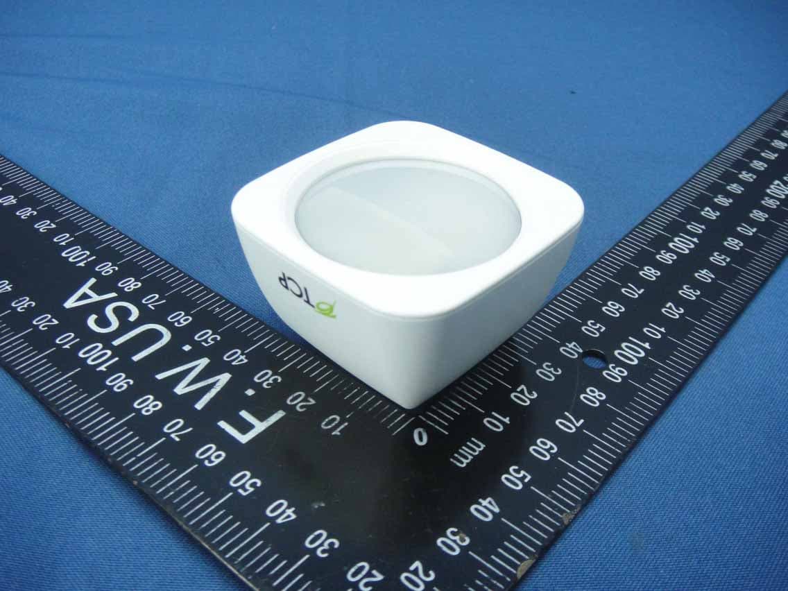
Jul 14, 2014Wireless Motion Sensor
Equipment Class
DTS - Digital Transmission System
Z3M-GUBW1J1
Apr 28, 2014Lighting Gateway
Equipment Class
DTS - Digital Transmission System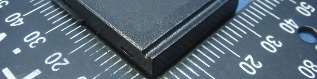
Z3M-ZBMOD1
Jan 16, 2014Zigbee Wireless Module
Equipment Class
DTS - Digital Transmission System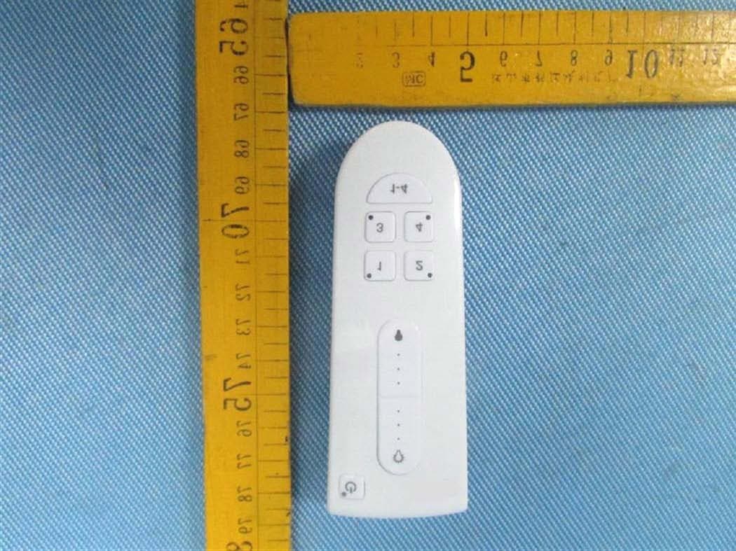
Z3M-GCM10
Feb 26, 2013LIGHTING CONTROLLER,JN,BUTTON,4CH
Equipment Class
DXX - Part 15 Low Power Communication Device Transmitter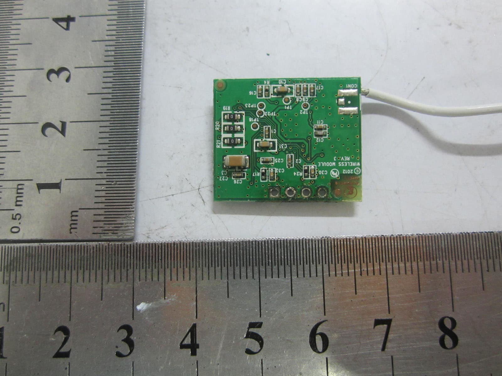
Z3M-GLA19147IAJNW
Nov 18, 2012Self-Ballasted LED-lamps
Equipment Class
DXX - Part 15 Low Power Communication Device Transmitter