Z3M-GCT10Touch Remote Control
Greenwave Reality Inc. d/b/a Greenwave Systems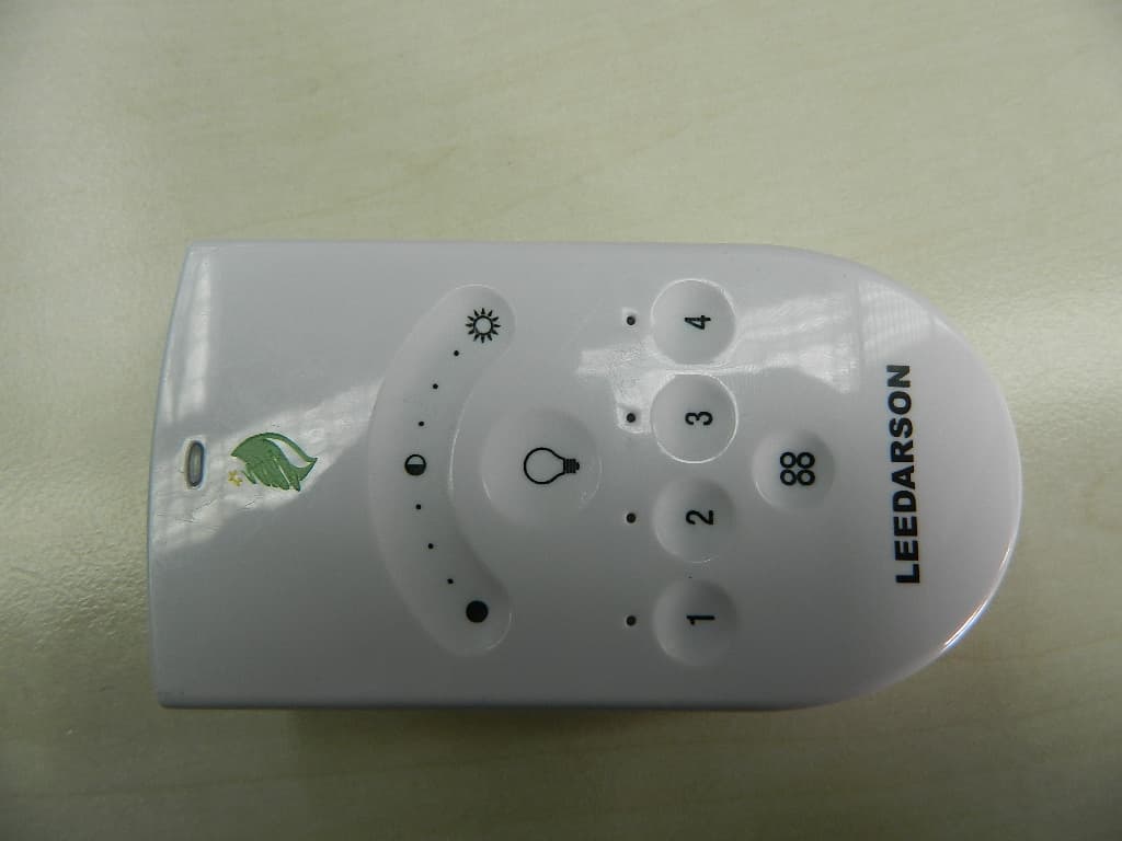
Click to zoom
Application Details
- Equipment Class
- DXX - Part 15 Low Power Communication Device Transmitter
- Date of Grant
- Mar 31, 2012
- Application Purpose
- Original Equipment
- Date of Application
- Mar 28, 2012
- Equipment Note
- Touch Remote Control
- Frequency Range
- 2405.00000000 - 2480.00000000
- Country
- United States
Documents & Files
Document Text
Text extracted from the exhibit documents filed with the FCC. Open a document above to read the original.
Users Manual
Lighting Kit with Remote Control Table of Contents Lighting Kit Overview 1 Basic Concepts of Wireless Lighting 1 Planning Your Lighting Network 2 Power Failure with Wireless Light Bulbs 4 Remote Control Overview 6 Indicators 7 Installation 8 Remote Control Operation 10 Turning Lights on and Off 11 Brightening and Dimming Lights 12 Changing a Light Bulb’s Lighting Group 12 Cloning a Remote Control 13 Replacing Batteries 14 Resetting the Remote Control to Factory Default Settings 14 Light Bulb Tasks 16 Adding Light Bulbs to the Network 16 Removing Light Bulbs from the Network 18 Optional Lighting Gateway 21 Troubleshooting 22 Safety Information 25 About GreenWave 28 Product Specifications 29 1 Lighting Kit Overview The GreenWave Reality lighting kit includes a wireless smart lighting system that helps make the lighting in your home more energy efficient and easier to manage. The kit includes LED or CFL light bulbs and a remote control that work together to help you manage your lighting wirelessly. Basic Concepts of Wireless Lighting Before setting up your wireless lighting network, you should take a few minutes to read through these basic concepts to understand how wireless lighting works and how it is different from standard lighting. Wireless light bulbs work with your light fixtures the same way as standard light bulbs. They are different, however, in a couple of ways: • The lighting element in the light bulb uses energy-efficient CFL technology or the more efficient LED technology. 2 • The light bulb includes wireless technology that allows the light bulb to connect to a network and be managed remotely. Because the light bulbs can be connected to a network, you have greater flexibility in how you use them. For example, you can program your lighting network so that when you press a button upon arriving home, an entryway and a hallway light turn on. Or when you go to bed, your remote control can turn off all lights on the network. Planning Your Lighting Network Whether you have only one wireless light bulb or you are replacing your entire home with wireless light bulbs, you should plan how you want the lighting on your network to behave. For example, if you only have one light bulb you might want to place it in a central location that would be optimum for turning on and off when you are away or arrive home. If you have multiple light bulbs, however, you might want to set them up in lighting groups to be able to better manage them across your home. Note: Light fixtures that have dimmer controls are not recommended for your network light bulbs. However, they can be used if the dimmer level is set to 100%. 3 Lighting Groups A lighting group is a set of network light bulbs that you can control together through your remote control. For example, you might have a lighting group that includes light bulbs on the same floor. Or you might have a group that includes hallway and entryway lights, making it easy to turn on or off as you arrive or leave home. All light bulbs in the same group turn on and off together and brighten or dim to the same level. The following limitations apply when working with network light bulbs and lighting groups in a system using remote control only: • One light bulb can belong to only one lighting group. • One remote control can control up to four different lighting groups. • One lighting group can contain up to 40 light bulbs (the maximum light bulbs allowed in a remote control only network). Note: By default, each light bulb in your lighting kit is pre-assigned to a lighting group. Numbering on the lighting kit package shows the lighting group to which each light bulb is assigned. Multi-fixture Lights When installing light bulbs or setting up lighting groups, you should consider how you want multi-fixture lights to behave. Since power to the light has to remain on (so the remote control can access the light bulb) you would use either all network light bulbs in a multi-fixture light or no network light bulbs at all. If you are using network light bulbs in a multi-fixture light, you should add them all to the same lighting group so that they turn on and off together (though you do not have to). 4 Network Range As with any remote control, your lighting kit’s remote control must be within range of your lighting network to be able to control your lighting. However, this does not mean that it has to be within range of all network light bulbs. Since the light bulbs are interconnected across the network, they can pass commands to each other as long as they are within network range of each other. This means that a nearby light bulb can receive your remote control command and pass that command across the network of connected light bulbs, ultimately to a light bulb you want to control in a distant room. Because of this effect, larger homes would make better use of having more network light bulbs spread across the home, maintaining a distance that allows each light bulb to communicate with one another. Maximum Number of Light Bulbs You can install up to 40 light bulbs on the same network to work with your remote control. Note: Networks that use a Lighting Gateway can hold more light bulbs. If you are interested in upgrading, you should refer to the Optional Lighting Gateway chapter for more information about its features. Power Failure with Wireless Light Bulbs Wireless light bulbs are powered through light fixtures the same way standard light bulbs are. However, you must leave the light fixtures in the on position so that power is available when using your remote control to turn the wireless light bulbs on and off. If power is removed from a light bulb, whether from power failure or from manually 5 turning off the light fixture, the light bulb will of course turn off. When power is restored, all network light bulbs affected by the power failure, regardless of whether they were previously on or off, will automatically turn on at full brightness. The affected light bulbs will maint…
Text truncated - open the document above for the full version.
External Photos
FCC ID: Z3M-GCT10 IC: 10257A-GCT10 Page 1 of 3 External Picture FCC ID: Z3M-GCT10 IC: 10257A-GCT10 Page 2 of 3 FCC ID: Z3M-GCT10 IC: 10257A-GCT10 Page 3 of 3
ID Label/Location Info
Label Location
Internal Photos
FCC ID: Z3M-GCT10 IC: 10257A-GCT10 Page 1 of 3 Internal Picture FCC ID: Z3M-GCT10 IC: 10257A-GCT10 Page 2 of 3 FCC ID: Z3M-GCT10 IC: 10257A-GCT10 Page 3 of 3
Test Report
FCC ID: Z3M-GCT10 IC: 10257A-GCT10 Page 1 of 17 EMC TEST REPORT for Intentional Radiator No. SH12030205-001 Applicant : Greenwave Reality Pte Ltd 41 Science Park Road, #03-01, The Gemini, Science Park II, Singapore 117610 Singapore Manufacturer : Leeleds Lighting (Xiamen) Co.,Ltd. Huli Branch No.5-7, Second Fanghu West Road, Huli District, Xiamen, China Product Name : Touch Remote Control Type/Model : CT1UV-Y-XX (“U” stands for “0-9/A-Z”; “V” stands for “0-9; “Y” stands for “0-9/A-Z”; “XX” stands for “00-99/AA-ZZ”) SUMMARY The equipment complies with the requirements according to the following standard(s): 47CFR Part 15 (2010): Radio Frequency Devices ANSIC63.4 (2003): American National Standard for Methods of Measurement of Radio-Noise Emissions from Low-Voltage Electrical and Electronic Equipment in the Range of 9 kHz to 40 GHz RSS-210 Issue 8 (December 2010): Low-power Licence-exempt Radiocommunication Devices (All Frequency Bands): Category I Equipment RSS-Gen Issue 3 (December 2010): General Requirements and Information for the Certification of Radiocommunication Equipment Date of issue: March 27, 2012 Prepared by: Reviewed by: Wakeyou Wang (Project Engineer) Daniel Zhao (Reviewer) FCC ID: Z3M-GCT10 IC: 10257A-GCT10 Page 2 of 17 Description of Test Facility Name: Intertek Testing Services Ltd. Shanghai ETL Semko Address: Building No.86, 1198 Qinzhou Road(North), Shanghai 200233, P.R. China FCC Registration Number: 236597 IC Assigned Code: 2042B-1 Name of contact: Steve Li Tel: +86 21 64956565 ext. 214 Fax: +86 21 54262335 ext. 214 FCC ID: Z3M-GCT10 IC: 10257A-GCT10 Page 3 of 17 Content SUMMARY .......................................................................................................................................................... 1 DESCRIPTION OF TEST FACILITY ......................................................................................................................... 2 1. GENERAL INFORMATION ............................................................................................................................ 4 1.1 Applicant Information ..................................................................................................... 4 1.2 Identification of the EUT ................................................................................................ 4 1.3 Technical specification ................................................................................................... 4 1.4 Mode of operation during the test / Test peripherals used .............................................. 5 2. TEST SPECIFICATION .................................................................................................................................. 6 2.1 Instrument list ................................................................................................................. 6 2.2 Test Standard .................................................................................................................. 6 3. RADIATED EMISSION ................................................................................................................................... 8 3.1 Test limit ......................................................................................................................... 8 3.2 Test Configuration .......................................................................................................... 8 3.3 Test procedure and test setup .......................................................................................... 9 3.4 Test protocol ................................................................................................................. 10 4. ASSIGNED BANDWIDTH (20DB BANDWIDTH) ............................................................................................ 10 4.1 Limit .............................................................................................................................. 12 4.2 Test Configuration ........................................................................................................ 12 4.3 Test procedure and test setup ........................................................................................ 12 4.4 Test protocol ................................................................................................................. 12 5. POWER LINE CONDUCTED EMISSION ........................................................................................................ 13 5.1 Limit .............................................................................................................................. 13 5.2 Test configuration ......................................................................................................... 13 5.3 Test procedure and test set up ....................................................................................... 14 5.4 Test protocol ................................................................................................................. 14 6. OCCUPIED BANDWIDTH ............................................................................................................................ 15 6.1 Test limit ....................................................................................................................... 15 6.2 Test Configuration ........................................................................................................ 15 6.3 Test procedure and test setup ........................................................................................ 15 6.4 Test protocol ................................................................................................................. 15 7. SPURIOUS EMISSION FOR RECEIVER ......................................................................................................... 16 7.1 Test limit ....................................................................................................................... 1…
Text truncated - open the document above for the full version.
Test Report
FCC ID: Z3M-GCT10 IC: 10257A-GCT10 Page 1 of 11 Test Data FCC ID: Z3M-GCT10 IC: 10257A-GCT10 Page 2 of 11 1. Radiated emission Horizontal 0 10 20 30 40 50 60 70 80 Level [dB 礦/m] 30M50M70M100M200M300M500M700M1G Frequency [Hz] x x x x x x MES wa120312_H5_red MES wa120312 H5pre FCC ID: Z3M-GCT10 IC: 10257A-GCT10 Page 3 of 11 Vertical 0 10 20 30 40 50 60 70 80 Level [dB 礦/m] 30M50M70M100M200M300M500M700M1G Frequency [Hz] x x x x x x MES wa120312_V5_red MES wa120312 V5pre FCC ID: Z3M-GCT10 IC: 10257A-GCT10 Page 4 of 11 2. Occupied bandwidth Channel L FCC ID: Z3M-GCT10 IC: 10257A-GCT10 Page 5 of 11 Channel M FCC ID: Z3M-GCT10 IC: 10257A-GCT10 Page 6 of 11 Channel H FCC ID: Z3M-GCT10 IC: 10257A-GCT10 Page 7 of 11 3. Assigned bandwidth (20dB bandwidth) Channel L FCC ID: Z3M-GCT10 IC: 10257A-GCT10 Page 8 of 11 Channel H From the data above, it was found the Assigned bandwidth is 2403.82MHz – 2481.16MHz. FCC ID: Z3M-GCT10 IC: 10257A-GCT10 Page 9 of 11 4. Duty Cycle Pulse train under sweep time of 100ms FCC ID: Z3M-GCT10 IC: 10257A-GCT10 Page 10 of 11 “On” time among one cycle FCC ID: Z3M-GCT10 IC: 10257A-GCT10 Page 11 of 11 The dwell time of one cycle The duty cycle = 2.94ms /5.74ms = 0.512
Test Setup Photos
FCC ID: Z3M-GCT10 IC: 10257A-GCT10 Page 1 of 7 Test Setup FCC ID: Z3M-GCT10 IC: 10257A-GCT10 Page 2 of 7 1. Radiated Emission 30MHz-1000MHz, X axis FCC ID: Z3M-GCT10 IC: 10257A-GCT10 Page 3 of 7 30MHz-1000MHz, Y axis FCC ID: Z3M-GCT10 IC: 10257A-GCT10 Page 4 of 7 30MHz-1000MHz, Z axis FCC ID: Z3M-GCT10 IC: 10257A-GCT10 Page 5 of 7 Higher than 1GHz, X axis FCC ID: Z3M-GCT10 IC: 10257A-GCT10 Page 6 of 7 Higher than 1GHz, Y axis FCC ID: Z3M-GCT10 IC: 10257A-GCT10 Page 7 of 7 Higher than 1GHz, Z axis
Contact Information
Applicant
Troy Pliska(Executive VP of Operations)
Technical Contact
Intertek Testing Services Limited ShanghaiWakeyou Wang
[email protected]86 21 61278448
Building No.86, 1198 Qinzhou Road(North) · Shanghai · China
Non-Technical Contact
Intertek Testing Services Limited ShanghaiWakeyou Wang
[email protected]86 21 61278448
Test Firm
Intertek Testing Services Limited ShanghaiJonny Jing
Technical Specifications
| # | Rule Parts | Frequency Range | Power Output |
|---|---|---|---|
| 1 | 15C | 2.40 GHz - 2.48 GHz | - |
Other Applications from Greenwave Reality Inc. d/b/a Greenwave Systems
Z3M-GSYP1J11
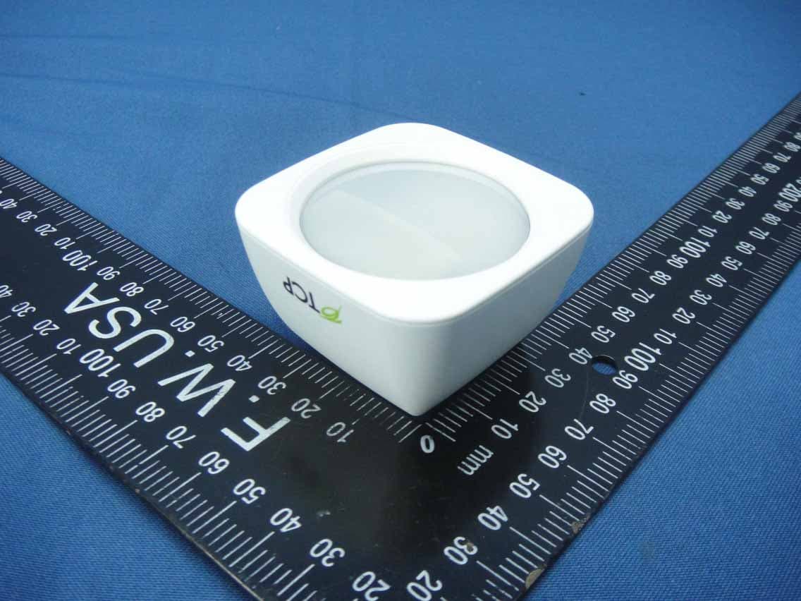
Jul 14, 2014Wireless Motion Sensor
Equipment Class
DTS - Digital Transmission System
Z3M-GUBW1J1
Apr 28, 2014Lighting Gateway
Equipment Class
DTS - Digital Transmission System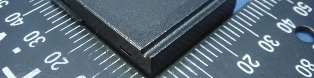
Z3M-ZBMOD1
Jan 16, 2014Zigbee Wireless Module
Equipment Class
DTS - Digital Transmission System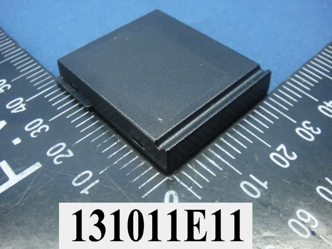
Z3M-JENMOD1
Jan 16, 2014Zigbee Wireless Module
Equipment Class
DTS - Digital Transmission System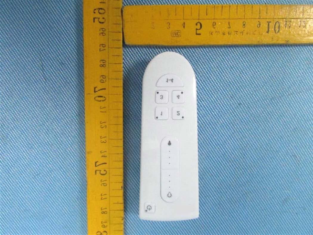
Z3M-GCM10
Feb 26, 2013LIGHTING CONTROLLER,JN,BUTTON,4CH
Equipment Class
DXX - Part 15 Low Power Communication Device Transmitter