Z3M-GGL32Lighting Gateway
Greenwave Reality Inc. d/b/a Greenwave Systems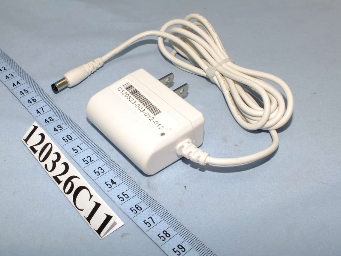
Click to zoom
Application Details
- Equipment Class
- DXX - Part 15 Low Power Communication Device Transmitter
- Date of Grant
- Apr 22, 2012
- Application Purpose
- Original Equipment
- Date of Application
- Apr 21, 2012
- Equipment Note
- Lighting Gateway
- Frequency Range
- 908.40000000 - 916.00000000
- Country
- United States
Documents & Files
Document Text
Text extracted from the exhibit documents filed with the FCC. Open a document above to read the original.
Users Manual
Lighting Kit with Gateway and Remote Control Table of Contents 找不到目錄項目。 1 Lighting Kit Overview The GreenWave Reality lighting kit includes a wireless smart lighting system that helps make the lighting in your home more energy efficient and easier to manage. The kit includes LED or CFL light bulbs and a remote control that work together to help you manage your lighting wirelessly. Your lighting kit also includes a GreenWave Reality Gateway, which provides an enhanced network connection to your light bulbs. This Gateway connection allows you to use your Web browser, smartphone, or other smart devices to set up and manage your home lighting system as well as set up user-defined schedules and other controls for automatically turning your lighting on or off. Note: This guide uses the term “smart device” to refer to a smartphone, tablet (or iTouch), or TV. 2 System Requirements To use a Web browser or smart device to manage your lighting, your computer or smart device and home network must meet the following minimum requirements. If your system does not meet these requirements, you can still use your lighting kit with the remote control. Computer (for Web Access) Active Internet connection (only if accessing your account remotely) Any of the following Web browsers - Microsoft Internet Explorer 8.0 and above - Mozilla Firefox 3.6 and above - Google Chrome 12.0 and above - Apple Safari 5.1.1 and above Smart Devices (Smartphone, Tablet, and TV) For Android devices: - Android operating system 2.2 and above - Screen resolution of 320x240 and above For Apple devices: - iOS operating system 4.2.1 and above 3 Wireless Router For the smart device application to manage your lighting locally within your home, your home network must use a wireless router to which your smart device is connected. While you can also connect remotely to your lighting network over the Internet or mobile data connection, it is not practical to do so on a day-to-day basis at home. There are no requirements for the type of wireless router, as long as your smart device and Gateway are able to connect to it. Refer to your smart device’s documentation for more information on connecting it to your home network. Note: Your network lighting is designed for a wireless home network and not a corporate network. Basic Concepts of Wireless Routers and Networks Many homes today have a home network router to allow multiple devices in the home to connect to the Internet as well as each other. Many people use a wireless router as their network router so that they are not tethered by a cable that physically connects them to the router. For example, most modern laptop computers and smart devices have internal wireless hardware that allows you to connect them to a wireless router without a physical cable. Modem and Router Connection In a typical home network configuration, the router (wireless or not) connects to a modem, which in turn connects to the Internet. For example, cable companies and DSL providers often provide their customers with a modem 4 that connects directly to the cable company or DSL provider’s network and thus to the Internet. You could connect a computer directly to this modem so that you can access the Internet through your computer’s Web browser or other applications. However, many people connect a router to the modem instead to allow for multiple computers and devices to all share the same connection to the Internet through one modem. The router also allows the attached computers and devices to connect with one another. Wireless Network Before wireless networking became common, routers only allowed for computers and devices to connect physically through cables. This limited where you could place your computer or device based on the location of the router and the length of the cable. With the advent of wireless networking in the home (commonly referred to as “wi-fi”), many routers began including wireless technology in addition to the physical cable connections. This type of wireless router allows you to connect a wireless-enabled device from anywhere around the home as long as the wireless radio signal can be maintained. Many of the computers and devices built today come with internal wireless hardware so that they are ready to connect to your wireless network. As a wireless device, a smart device can connect to a wireless network, and applications installed on the smart device (including the lighting application) use that network connection to access the Internet or other devices on the home network. Since any wireless device within radio range can connect to a wireless router (and thus the corresponding home network), wireless routers allow you to set up a user name and password so that wireless devices must be authenticated in order to connect. Modern smart devices support this type of wireless infrastructure. Typically, when you set up your wireless settings on your smart device, you store the user name and password for your wireless network so that your smart device is always connected when in range of your home network. 5 Wireless Lighting Network Wireless lighting uses your router’s wireless technology to allow you to control and manage your lights from a smart device. To do this, the Gateway in your lighting kit is built to communicate with the wireless light bulbs. Since the Gateway connects to your wireless router, other devices connected to that same router (such as your smart device) can access the Gateway. With your wireless light bulbs connected to the Gateway, your smart device can control them as long as the smart device is running the appropriate application. The lighting application enables your smart device to connect to the Gateway through your wireless router connection and in turn control and manage the attached network lighting. Local vs. Remote Connection In networking, you will commonly hear the following terms to describe how a device may be connecting to the network: Local refers to a ne…
Text truncated - open the document above for the full version.
External Photos
Page 1 CONSTRUCTION PHOTOS OF EUT Page 2 Page 3
ID Label/Location Info
Label drawing
Internal Photos
Page 4 Page 5 Page 6 Page 7
Operational Description
FCC ID: Z3M-GGL32 Report No.: RF120326C11 Operational Description The transmitter of the EUT (Lighting Gateway) is powered by by 5Vdc from AC adapter. The output power of this device is very low. Under normal use condition, the transmitter and the receiver are quite close, so high EIRP power is neither necessary nor allowed because of interference. For more detailed instruction, please take a look at the user’s manual.
Test Report
Report No.: RF120326C11 1 Report Format Version 4.2.0 FCC TEST REPORT REPORT NO.: RF120326C11 MODEL NO.: GL32200-xy (refer to item 3.1 for more detail) FCC ID: Z3M-GGL32 RECEIVED: Mar. 26, 2012 TESTED: Mar. 31 ~ Apr. 07, 2012 ISSUED: Apr. 10, 2012 APPLICANT : Greenwave Reality Pte Ltd ADDRESS : 41 Science Park Road, #03-01, The Gemini, Science Park II, Singapore 117610. ISSUED BY: Bureau Veritas Consumer Products Services (H.K.) Ltd., Taoyuan Branch LAB ADDRESS: No. 47, 14th Ling, Chia Pau Vil., Lin Kou Dist., New Taipei City, Taiwan ( R.O.C. ) TEST LOCATION: No. 19, Hwa Ya 2nd Rd, Wen Hwa Tsuen, Kwei Shan Hsiang, Taoyuan Hsien 333, Taiwan, R.O.C. This test report consists of 47 pages in total. It may be duplicated completely for legal use with the approval of the applicant. It should not be reproduced except in full, without the written approval of our laboratory. The client should not use it to claim product, certification, approval or endorsement by TAF or any government agency. The test results in the report only apply to the tested sample. The test results in this report are traceable to the national or international standards. Report No.: RF120326C11 2 Report Format Version 4.2.0 Table of Contents RELEASE CONTROL RECORD ............................................................................................... 3 1. CERTIFICATION ........................................................................................................... 4 2. SUMMARY OF TEST RESULTS ................................................................................... 5 2.1 MEASUREMENT UNCERTAINTY ................................................................................ 5 3. GENERAL INFORMATION ............................................................................................ 6 3.1 GENERAL DESCRIPTION OF EUT .............................................................................. 6 3.2 DESCRIPTION OF TEST MODES ................................................................................ 7 3.2.1 TEST MODE APPLICABILITY AND TESTED CHANNEL DETAIL ................................ 8 3.3 DESCRIPTION OF SUPPORT UNITS ........................................................................ 12 3.3.1 CONFIGURATION OF SYSTEM UNDER TEST ......................................................... 12 3.4 GENERAL DESCRIPTION OF APPLIED STANDARDS ............................................. 13 4. TEST TYPES AND RESULTS ..................................................................................... 14 4.1 RADIATED EMISSION AND BAND EDGE MEASUREMENT ..................................... 14 4.1.1 LIMITS OF RADIATED EMISSION MEASUREMENT ................................................. 14 4.1.2 TEST INSTRUMENTS ................................................................................................ 15 4.1.3 TEST PROCEDURES ................................................................................................. 16 4.1.4 DEVIATION FROM TEST STANDARD ....................................................................... 16 4.1.5 TEST SETUP .............................................................................................................. 17 4.1.6 EUT OPERATING CONDITIONS ................................................................................ 17 4.1.7 TEST RESULTS .......................................................................................................... 18 4.2 CONDUCTED EMISSION MEASUREMENT .............................................................. 34 4.2.1 LIMITS OF CONDUCTED EMISSION MEASUREMENT............................................ 34 4.2.2 TEST INSTRUMENTS ................................................................................................ 34 4.2.3 TEST PROCEDURES ................................................................................................. 35 4.2.4 DEVIATION FROM TEST STANDARD ....................................................................... 35 4.2.5 TEST SETUP .............................................................................................................. 36 4.2.6 EUT OPERATING CONDITIONS ................................................................................ 36 4.2.7 TEST RESULTS .......................................................................................................... 37 5. PHOTOGRAPHS OF THE TEST CONFIGURATION .................................................. 45 6. INFORMATION ON THE TESTING LABORATORIES ................................................ 46 7. APPENDIX A - MODIFICATIONS RECORDERS FOR ENGINEERING CHANGES TO THE EUT BY THE LAB ......................................................................................... 47 Report No.: RF120326C11 3 Report Format Version 4.2.0 RELEASE CONTROL RECORD ISSUE NO. REASON FOR CHANGE DATE ISSUED RF120326C11 Original release Apr. 10, 2012 Report No.: RF120326C11 4 Report Format Version 4.2.0 1. CERTIFICATION PRODUCT: Lighting Gateway MODEL NO.: GL32200-xy (refer to item 3.1 for more detail) BRAND: greenWAVE APPLICANT: Greenwave Reality Pte Ltd TESTED: Mar. 31 ~ Apr. 07, 2012 TEST SAMPLE: ENGINEERING SAMPLE STANDARDS: FCC Part 15, Subpart C (Section 15.249) ANSI C63.10-2009 The above equipment (model: GL32200-xy) have been tested by Bureau Veritas Consumer Products Services (H.K.) Ltd., Taoyuan Branch, and found compliance with the requirement of the above standards. The test record, data evaluation & Equipment Under Test (EUT) configurations represented herein are true and accurate accounts of the measurements of the sample’s EMC characteristics under the conditions specified in this report. PREPARED BY : , DATE:Apr. 10, 2012 Andrea Hsia / Specialist APPROVED BY : , DATE:Apr. 10, 2012 Gary Chang / Technical Manager Report No.: RF120326C11 5 Report Format Version 4.2.0 2. SUMMARY OF TEST RESULTS The EUT has been tested according to the following specifications: APPLIED STANDARD: FCC Part 15, Subp…
Text truncated - open the document above for the full version.
Test Setup Photos
1 PHOTOGRAPHS OF THE TEST CONFIGURATION CONDUCTED EMISSION TEST 2 RADIATED EMISSION TEST
Contact Information
Applicant
Troy Pliska(Executive VP of Operations)
Technical Contact
Bureau Veritas CPS (H.K.) Ltd. Taoyuan BranchGary Chang
[email protected]886-3-3183232
No. 19, Hwa Ya 2nd Rd., Kwei Shan Hsiang · Taoyuan Hsien · Taiwan
Non-Technical Contact
Bureau Veritas CPS (H.K.) Ltd. Taoyuan BranchNatacha Chen
[email protected]886-3-3183232
Test Firm
Bureau Veritas CPS (H.K.) Ltd. Taoyuan BranchRichard Chen
Technical Specifications
| # | Rule Parts | Frequency Range | Power Output |
|---|---|---|---|
| 1 | 15C | 908.4 MHz - 916 MHz | - |
Other Applications from Greenwave Reality Inc. d/b/a Greenwave Systems
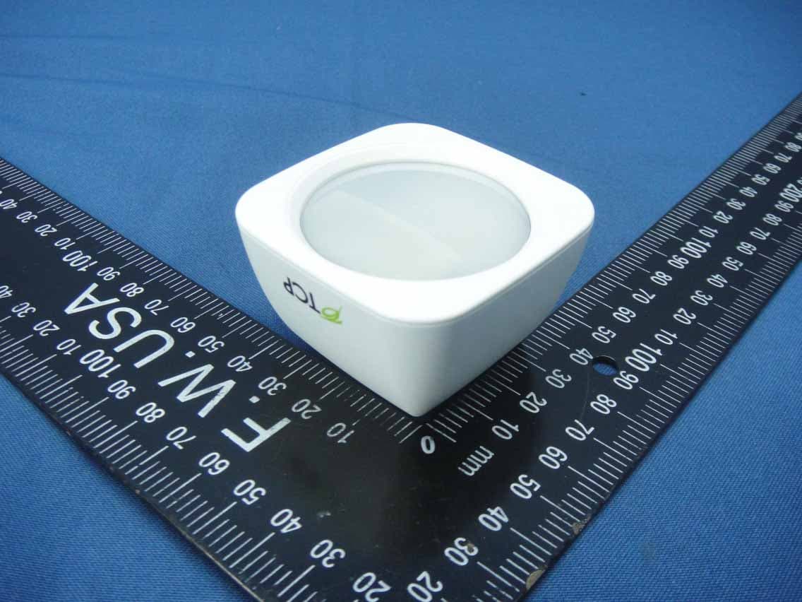
Z3M-GSYP1J11
Jul 14, 2014Wireless Motion Sensor
Equipment Class
DTS - Digital Transmission System
Z3M-GUBW1J1
Apr 28, 2014Lighting Gateway
Equipment Class
DTS - Digital Transmission System
Z3M-ZBMOD1
Jan 16, 2014Zigbee Wireless Module
Equipment Class
DTS - Digital Transmission System
Z3M-JENMOD1
Jan 16, 2014Zigbee Wireless Module
Equipment Class
DTS - Digital Transmission System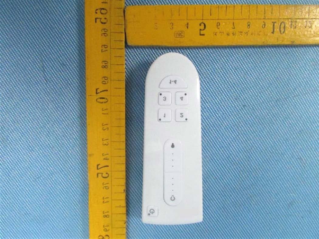
Z3M-GCM10
Feb 26, 2013LIGHTING CONTROLLER,JN,BUTTON,4CH
Equipment Class
DXX - Part 15 Low Power Communication Device Transmitter