Z3M-GNP22Power Node
Greenwave Reality Inc. d/b/a Greenwave Systems
Click to zoom
Application Details
- Equipment Class
- DXX - Part 15 Low Power Communication Device Transmitter
- Date of Grant
- Nov 17, 2011
- Application Purpose
- Original Equipment
- Date of Application
- Nov 17, 2011
- Equipment Note
- Power Node
- Frequency Range
- 908.40000000 - 916.00000000
- Country
- United States
Documents & Files
Document Text
Text extracted from the exhibit documents filed with the FCC. Open a document above to read the original.
Users Manual
PowerNodes NP220-B, NP222-B NS220-B, NS222-B Table of Contents Introduction 1 PowerNode Overview 2 One-Port PowerNode 3 Multi-Port PowerNode 4 Installation 9 Common Z-Wave Tasks 14 Network Inclusion Process 14 Network Exclusion Process 16 Safety Information 18 About GreenWave 19 Product Specifications 20 The GreenWave Reality platform helps create a smart, energy controlling of your appliances and electronics (referred to as impact to your lifestyle by using our products to easily manage your devices. Simply connect our Gateway to your GreenWave Reality energy management system and control the devices’ power usage through a Web browser or Introduction The GreenWave Reality platform helps create a smart, energy-efficient home through the monitoring and appliances and electronics (referred to as “devices”). You can conserve energy with minimal impact to your lifestyle by using our products to easily manage your devices. Simply connect our Gateway to GreenWave Reality energy management system, plug your devices into our PowerNodes, and then mo and control the devices’ power usage through a Web browser or smartphone application. 1 efficient home through the monitoring and . You can conserve energy with minimal impact to your lifestyle by using our products to easily manage your devices. Simply connect our Gateway to , plug your devices into our PowerNodes, and then monitor 2 PowerNode Overview The GreenWave Reality PowerNode is a smart outlet adapter that connects your your GreenWave Reality energy man usage remotely through a Web browser or multi-port configuration. The PowerNode automatically connects to your Green home network). This connection enables the Gateway to securely connect the devices you have powered through your PowerNode to your energy management system. The PowerNode collects data on the energy consumption of the connected devices and transmits the data to the Gateway. You can then control the energy consumption of each connected device automatically using GreenWave Reality Smart Controls. These user-defined Smart Controls allow you to turn devices on or off remotely through a Web browser or application or to set a schedule for automatically turning your devices on or off at pre-defined times. PowerNode Overview The GreenWave Reality PowerNode is a smart outlet adapter that connects your devices to electrical outlets and energy management system so that you can monitor and control your devices’ power usage remotely through a Web browser or smartphone application. PowerNodes are available with a one The PowerNode automatically connects to your GreenWave Reality Gateway (the device that connects to your home network). This connection enables the Gateway to securely connect the devices you have powered through your PowerNode to . The PowerNode collects data on the energy consumption of the connected devices and transmits the data to the Gateway. You can then control the energy consumption of each connected device automatically using GreenWave Reality fined Smart Controls allow you to turn devices on or off remotely through a Web browser or smartphone or to set a schedule for automatically turning your devices to electrical outlets and so that you can monitor and control your devices’ power PowerNodes are available with a one-port or Wave Reality Gateway (the device that connects to your One-Port PowerNode 5 4 1. PowerNode plug into your electrical 2. PowerNode in your device. 3. Room color selector rotate to specify the associated room color. 4. Sync button sync PowerNode with Gateway process call 5. Activity indicator and power on/off button. Shows the status of synced devices, and allows you to manually turn the PowerNode ports on or off. multi-port PowerNodes, the power button turns on 1 2 3 3 PowerNode plug: Prongs that you plug electrical outlet. PowerNode socket: Port where you plug your device. Room color selector: Wheel that you specify the associated room button: Button that you press to sync PowerNode with Gateway (a process called “inclusion”). Activity indicator and power on/off button. Shows the status of synced devices, and allows you to manually turn the PowerNode ports on or off. For port PowerNodes, the power button turns on or off all ports. 4 Multi-Port PowerNode 1. PowerNode power cord: Power cord that you plug into your electrical outlet. 2. PowerNode sockets: Ports where you plug in your devices. 3. Room color selector: Wheel that you rotate to specify the associated room color. 4. Activity indicator and power on/off button. Shows the status of synced devices, and allows you to manually turn the PowerNode ports on or off. For multi-port PowerNodes, the power button turns on or off all ports. 5. Sync button: Button that you press to sync PowerNode with Gateway (a process called “inclusion”). 5 1 2 3 4 5 Room Colors Your PowerNode has a corner wheel with colored numbers to represent the room or device that the PowerNode is powering. Set the PowerNode to the colored number you want to use to identify the room or device (this is referred to as the “room color”). For example, you can set the room color to blue. Then, when you access your account through the Web or smartphone application, the corresponding room is identified by the same blue color as your PowerNode. You can set PowerNodes in different rooms to different colors to make those rooms easy to identify when managing the power sources on the Web or smartphone application. Special Wheel Colors The PowerNode includes unnumbered white and black wheel colors that each serve a special purpose. The white wheel color (which also contains a lock icon) is the locked position. Setting a PowerNode to white enables monitoring but disables power management. You can monitor energy use information for devices plugged into a PowerNode using the white wheel color, but you cannot power those devices on or off remotely (for example, through Smart Controls). White is suggested for appliances such as refrigerators or medi…
Text truncated - open the document above for the full version.
External Photos
Page 1 CONSTRUCTION PHOTOS OF EUT
ID Label/Location Info
Label
Internal Photos
Page 2 Page 3 Page 4 Page 5 Page 6
Operational Description
FCC ID: Z3M-GNP22 Report No.: RF110926C28 Operational Description The transmitter of the EUT (power node) is powered by 100-240Vac from AC adapter. The output power of this device is very low. Under normal use condition, the transmitter and the receiver are quite close, so high EIRP power is neither necessary nor allowed because of interference. The antenna is Dipole antenna without antenna connectors. For more detailed instruction, please take a look at the user’s manual.
Test Report
Report No.: RF110926C28 1 Report Format Version 4.0.0 FCC TEST REPORT REPORT NO. :RF110926C28 MODEL NO. :NP220-B (refer to item 3.1 for more details) FCC ID :Z3M-GNP22 RECEIVED :Sep. 26, 2011 TESTED :Oct. 20 ~ Oct. 31, 2011 ISSUED :Nov. 03, 2011 APPLICANT : Greenwave Reality Pte Ltd ADDRESS : 41 Science Park Road, #03-01, The Gemini, Science Park II, Singapore 117610 ISSUED BY : Bureau Veritas Consumer Products Services (H.K.) Ltd., Taoyuan Branch LAB ADDRESS : No. 47, 14th Ling, Chia Pau Vil., Lin Kou Dist., New Taipei City, Taiwan ( R.O.C ) TEST LOCATION : No. 19, Hwa Ya 2nd Rd, Wen Hwa Tsuen, Kwei Shan Hsiang, Taoyuan Hsien 333, Taiwan, R.O.C. This test report consists of 40 pages in total. It may be duplicated completely for legal use with the approval of the applicant. It should not be reproduced except in full, without the written approval of our laboratory. The client should not use it to claim product, certification, approval or endorsement by TAF or any government agency. The test results in the report only apply to the tested sample. The test results in this report are traceable to the national or international standards. Report No.: RF110926C28 2 Report Format Version 4.0.0 Table of Contents RELEASE CONTROL RECORD...............................................................................................3 1. CERTIFICATION ...........................................................................................................4 2. SUMMARY OF TEST RESULTS ...................................................................................5 2.1 MEASUREMENT UNCERTAINTY ................................................................................5 3. GENERAL INFORMATION............................................................................................6 3.1 GENERAL DESCRIPTION OF EUT..............................................................................6 3.2 DESCRIPTION OF TEST MODES................................................................................7 3.2.1 CONFIGURATION OF SYSTEM UNDER TEST ...........................................................7 3.2.2 TEST MODE APPLICABILITY AND TESTED CHANNEL DETAIL ................................8 3.3 GENERAL DESCRIPTION OF APPLIED STANDARDS ...............................................9 3.4 DESCRIPTION OF SUPPORT UNITS ........................................................................10 4. TEST TYPES AND RESULTS ..................................................................................... 11 4.1 RADIATED EMISSION MEASUREMENT ................................................................... 11 4.1.1 LIMITS OF RADIATED EMISSION MEASUREMENT................................................. 11 4.1.2 TEST INSTRUMENTS ................................................................................................12 4.1.3 TEST PROCEDURES .................................................................................................13 4.1.4 DEVIATION FROM TEST STANDARD .......................................................................13 4.1.5 TEST SETUP ..............................................................................................................14 4.1.6 EUT OPERATING CONDITIONS ................................................................................14 4.1.7 TEST RESULTS ..........................................................................................................15 4.2 CONDUCTED EMISSION MEASUREMENT ..............................................................30 4.2.1 LIMITS OF CONDUCTED EMISSION MEASUREMENT............................................30 4.2.2 TEST INSTRUMENTS ................................................................................................30 4.2.3 TEST PROCEDURES .................................................................................................31 4.2.4 DEVIATION FROM TEST STANDARD .......................................................................31 4.2.5 TEST SETUP ..............................................................................................................32 4.2.6 EUT OPERATING CONDITIONS ................................................................................32 4.2.7 TEST RESULTS ..........................................................................................................33 4.3 BAND EDGES MEASUREMENT ................................................................................35 4.3.1 LIMITS OF BAND EDGES MEASUREMENT .............................................................35 4.3.2 TEST INSTRUMENTS ................................................................................................35 4.3.3 TEST PROCEDURE ...................................................................................................35 4.3.4 DEVIATION FROM TEST STANDARD .......................................................................35 4.3.5 EUT OPERATING CONDITION ..................................................................................35 4.3.6 TEST RESULTS ..........................................................................................................36 5. PHOTOGRAPHS OF THE TEST CONFIGURATION..................................................38 6. INFORMATION ON THE TESTING LABORATORIES ................................................39 7. APPENDIX A - MODIFICATIONS RECORDERS FOR ENGINEERING CHANGES TO THE EUT BY THE LAB.........................................................................................40 Report No.: RF110926C28 3 Report Format Version 4.0.0 RELEASE CONTROL RECORD ISSUE NO. REASON FOR CHANGE DATE ISSUED Original release NA Nov. 03, 2011 Report No.: RF110926C28 4 Report Format Version 4.0.0 1. CERTIFICATION PRODUCT: Power Node MODEL NO.: NP220-B (refer to item 3.1 for more details) BRAND: greenWAVE APPLICANT: Greenwave Reality Pte Ltd TESTED: Oct. 20 ~ Oct. 31, 2011 TEST SAMPLE: ENGINEERING SAMPLE STANDARDS: FCC Part 15, Subpa…
Text truncated - open the document above for the full version.
Test Setup Photos
1 PHOTOGRAPHS OF THE TEST CONFIGURATION CONDUCTED EMISSION TEST 2 RADIATED EMISSION TEST
Contact Information
Applicant
Troy Pliska(Executive VP of Operations)
Technical Contact
Bureau Veritas CPS (H.K.) Ltd. Taoyuan BranchGary Chang
[email protected]886-3-3183232
No. 19, Hwa Ya 2nd Rd., Kwei Shan Hsiang · Taoyuan Hsien · Taiwan
Non-Technical Contact
Bureau Veritas CPS (H.K.) Ltd. Taoyuan BranchNatacha Chen
[email protected]886-3-3183232
Test Firm
Bureau Veritas CPS (H.K.) Ltd. Taoyuan BranchRichard Chen
Technical Specifications
| # | Rule Parts | Frequency Range | Power Output |
|---|---|---|---|
| 1 | 15C | 908.4 MHz - 916 MHz | - |
Other Applications from Greenwave Reality Inc. d/b/a Greenwave Systems
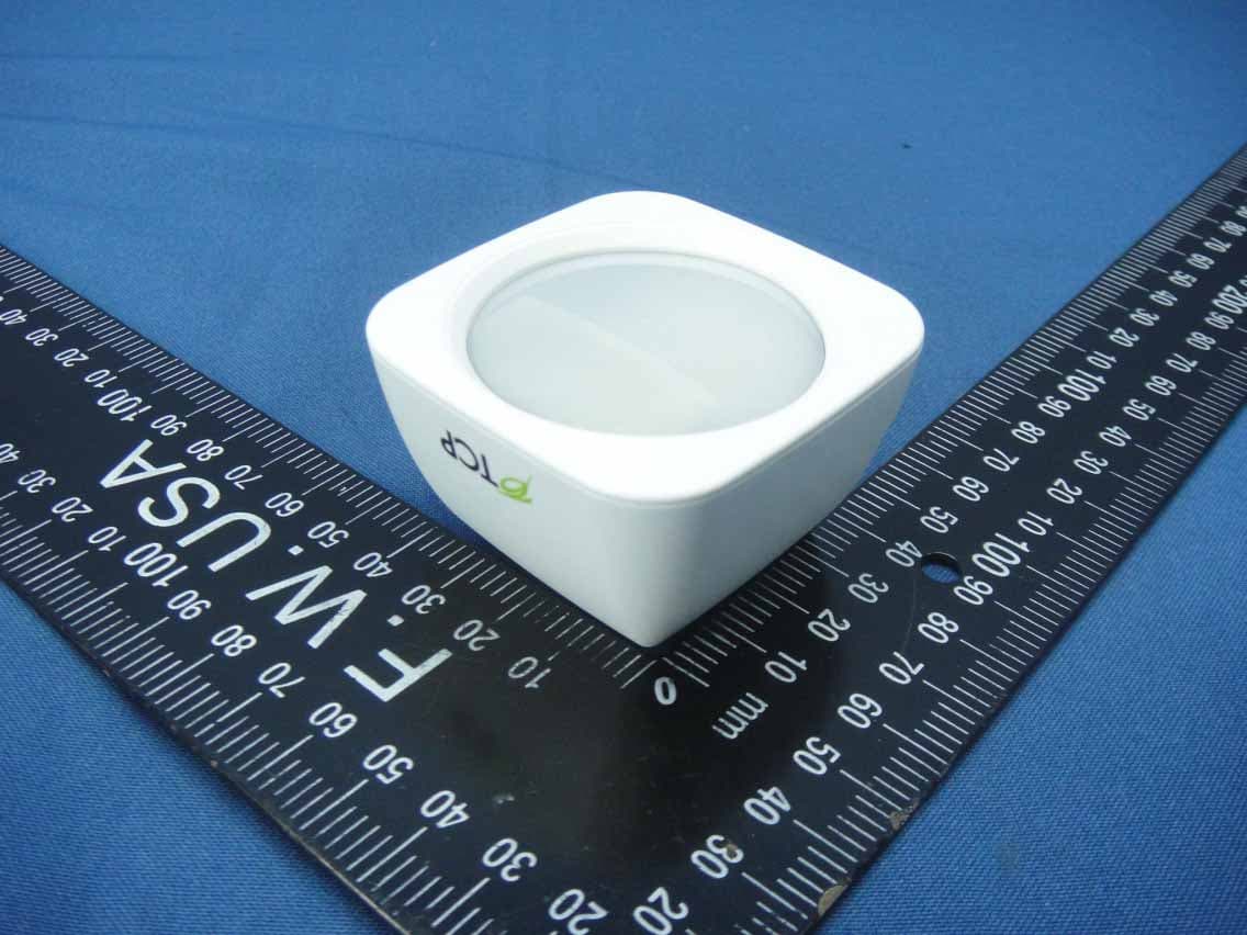
Z3M-GSYP1J11
Jul 14, 2014Wireless Motion Sensor
Equipment Class
DTS - Digital Transmission System
Z3M-GUBW1J1
Apr 28, 2014Lighting Gateway
Equipment Class
DTS - Digital Transmission System
Z3M-ZBMOD1
Jan 16, 2014Zigbee Wireless Module
Equipment Class
DTS - Digital Transmission System
Z3M-JENMOD1
Jan 16, 2014Zigbee Wireless Module
Equipment Class
DTS - Digital Transmission System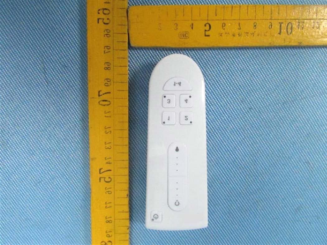
Z3M-GCM10
Feb 26, 2013LIGHTING CONTROLLER,JN,BUTTON,4CH
Equipment Class
DXX - Part 15 Low Power Communication Device Transmitter