Z3M-GRPS10Meter Reader
Greenwave Reality Inc. d/b/a Greenwave Systems
Click to zoom
Application Details
- Equipment Class
- DTS - Digital Transmission System
- Date of Grant
- Nov 08, 2011
- Application Purpose
- Original Equipment
- Date of Application
- Nov 08, 2011
- Equipment Note
- Meter Reader
- Frequency Range
- 2405.00000000 - 2480.00000000
- Country
- United States
Documents & Files
Document Text
Text extracted from the exhibit documents filed with the FCC. Open a document above to read the original.
Users Manual
DOCUMENT TRACKING – REMOVE THIS SECTION BEFORE FINAL PRODUCTION Date By Notes 8/10/2011 Kevin Lewis New version 1.01. Meter Reader RPS1005 RPS1015 Table of Contents Introduction 1 Pulse Reader Overview 2 Installation 3 Safety Information 7 About GreenWave 10 The GreenWave Reality platform helps create a smart, energy controlling of your appliances and electronics (referred to as “devices”). You can conserve energy with minimal impact to your lifestyle by using our products to easily manage your devices. Simply connect our Gateway to your GreenWave Reality energy manage and control the devices’ power usage through a Web browser or smartphone application. Introduction The GreenWave Reality platform helps create a smart, energy-efficient home through the monitoring and controlling of your appliances and electronics (referred to as “devices”). You can conserve energy with minimal impact to your lifestyle by using our products to easily manage your devices. Simply connect our Gateway to your GreenWave Reality energy management system, plug your devices into our PowerNodes, and then monitor and control the devices’ power usage through a Web browser or smartphone application. 1 efficient home through the monitoring and controlling of your appliances and electronics (referred to as “devices”). You can conserve energy with minimal impact to your lifestyle by using our products to easily manage your devices. Simply connect our Gateway to ment system, plug your devices into our PowerNodes, and then monitor 2 Pulse Reader The GreenWave Reality Pulse Reader to measure energy usage. The information be transmitted to your GreenWave R control your energy use. The Pulse Reader is weather-resistant and designed to be mounted next to electric and/or gas meters. Pulse Reader Overview Pulse Reader connects to your electric and/or gas meters information read through the Pulse Reader can then Reality Gateway so that you can monitor and resistant and designed to be mounted next to your You must follow several installation steps • Preparing for installation • Attaching the self-adhesive template to the meter to ensure accurate • Attaching the Pulse Reader sensors to your meter(s) • Installing batteries, if they are not already pre • Securing the Pulse Reader unit in place near your meter(s) 1. Prepare for Installation Before you can connect the Pulse Reader, you must first locate the area on your meter(s) where you will attach its sensors. You should clean the area to ensure it is free from dirt or grease. If your specific setup process requires you to record your current meter readings, then make not any obstructed view of the meter after Installation several installation steps to connect your Pulse Reader to your meter. These steps include: Preparing for installation adhesive template to the meter to ensure accurate placement of the sensors Attaching the Pulse Reader sensors to your meter(s) batteries, if they are not already pre-installed Securing the Pulse Reader unit in place near your meter(s) Prepare for Installation Reader, you must first locate the area on your meter(s) where you will attach its sensors. You should clean the area to ensure it is free from dirt or grease. If your specific setup process requires you to record your current meter readings, then make note of them before you begin installation to avoid any obstructed view of the meter after attaching the Pulse Reader sensors. You may need to note 3 These steps include: placement of the sensors Reader, you must first locate the area on your meter(s) where you will attach its sensors. You should clean the area to ensure it is free from dirt or grease. If your specific setup process e of them before you begin installation to avoid attaching the Pulse Reader sensors. You may need to note both the 4 current reading and the base value: The exact target area on your meter depends on whether it is an electric or gas meter, as well as the specific type. 2. Attach Template to Meter Since placement of the Pulse Reader cable sensor on the meter is critical, your kit includes self-adhesive templates to help you align the sensor. Visually align the marking on the template to the target placement on your meter. When you are sure of the placement and where to align the marking on each template, remove the adhesive backing from the template and stick it to the meter. Be careful to ensure that the template’s marking is placed exactly over the target sensor placement on the meter. After sticking the template to your meter, remove the middle portion of the template that contains the alignment marking. This area is perforated to help you remove it. You should be left with two sides of the template still stuck to your meter. This is the area where you will align the Pulse Reader sensor. 5 3. Attach Sensor to Meter Before removing the adhesive backing from the cable sensor, make sure it aligns correctly over the open area of the template. The grey-colored sensor attaches to your gas meter, and the white-colored sensor attaches to your electric meter. As you align the sensor over the template, make sure there will be no overhang of the sensor that might extend far over the template area. If necessary, the edges of the sensor are perforated to allow you to break it to make the surface area smaller. When you are sure of the placement and fit of the cable sensor, remove its adhesive backing and stick the sensor to the open area of the template. The sensor should stick directly to the meter and not to the template edges. When the sensor is securely attached to the meter, you can remove the template edges by peeling them off of the meter. 4. Install Batteries Your Pulse Reader comes with four AA lithium (FR6) batteries. If these batteries are not already pre-installed, then remove the cover from the battery compartment on the back of the Pulse Reader unit, insert the batteries as indicated on the markings in the battery compartment, and then replace the cover. CAUTION: R…
Text truncated - open the document above for the full version.
External Photos
Page 1 CONSTRUCTION PHOTOS OF EUT Page 2 Page 3 EUT with USB port Page 4 EUT without USB port Page 5 Dipole Antenna Page 6 Monopole Antenna Page 7
Internal Photos
Page 8 Page 9 Page 10 Page 11
Operational Description
FCC ID: Z3M-GRPS10 Report No.: RF110803C25 Operational Description This device is a Meter Reader. The transmitter of the EUT is powered by 5Vdc from adapter or 6Vdc from batteries. The antenna information is as below: For more detailed instruction, please take a look at the user’s manual.
RF Exposure Info
Report No.: SA110803C25 Report Format Version 4.0.0 1 RF EXPOSURE REPORT REPORT NO.: SA110803C25 MODEL NO.: RPS1015-PD62-QQ, RPS10X5-YYZU, (X : 0 or 1;YY: PD, ES, EP, MR, PA, PM; Z : /, 2, 4, 6, 8, A, E, N; U : /, 0, 1, 2, 3, 4, 5, 6) RPS10X5-YYZU-VV (X : 0 or 1;YY: PD, ES, EP, MR, PA, PM; Z : /, 2, 4, 6, 8, A, E, N;U : /, 0, 1, 2, 3, 4, 5, 6;V: /, A~Z, 0~9) FCC ID: Z3M-GRPS10 APPLICANT: Greenwave Reality Pte Ltd ADDRESS: 41 Science Park Road, #03-01, The Gemini, Science Singapore 117610 ISSUED BY: Bureau Veritas Consumer Products Services (H.K.) Ltd., Taoyuan Branch LAB ADDRESS: No. 47, 14th Ling, Chia Pau Tsuen, Lin Kou Hsiang, Taipei Hsien 244, Taiwan, R.O.C. TEST LOCATION: No. 19, Hwa Ya 2nd Rd, Wen Hwa Tsuen, Kwei Shan Hsiang, Taoyuan Hsien 333, Taiwan, R.O.C. This test report consists of 5 pages in total. It may be duplicated completely for legal use with the approval of the applicant. It should not be reproduced, except in full, without the written approval of our laboratory. The client should not use it to claim product, certification, approval, or endorsement by any government agency. The test results in the report only apply to the tested sample. Report No.: SA110803C25 Report Format Version 4.0.0 2 TABLE OF CONTENTS RELEASE CONTROL RECORD ............................................................................................. 3 1. CERTIFICATION .......................................................................................................... 4 2. RF EXPOSURE............................................................................................................ 5 2.1 LIMITS FOR MAXIMUM PERMISSIBLE EXPOSURE (MPE)...................................... 5 2.2 MPE CALCULATION FORMULA ................................................................................. 5 2.3 CLASSIFICATION ........................................................................................................ 5 2.4 CALCULATION RESULT OF MAXIMUM CONDUCTED POWER............................... 5 Report No.: SA110803C25 Report Format Version 4.0.0 3 RELEASE CONTROL RECORD ISSUE NO. REASON FOR CHANGE DATE ISSUED Original release NA Sep. 13, 2011 Report No.: SA110803C25 Report Format Version 4.0.0 4 1. CERTIFICATION PRODUCT: Meter Reader MODEL NO.: RPS1015-PD62-QQ, RPS10X5-YYZU, (X : 0 or 1;YY: PD, ES, EP, MR, PA, PM; Z : /, 2, 4, 6, 8, A, E, N;U : /, 0, 1, 2, 3, 4, 5, 6) RPS10X5-YYZU-VV (X : 0 or 1;YY: PD, ES, EP, MR, PA, PM; Z : /, 2, 4, 6, 8, A, E, N;U : /, 0, 1, 2, 3, 4, 5, 6;V: /, A~Z, 0~9) BRAND: greenWAVE REALITY APPLICANT: Greenwave Reality Pte Ltd TESTED: Jul. 19 ~ Jul. 20, 2011 TEST SAMPLE: ENGINEERING SAMPLE STANDARDS: FCC Part 2 (Section 2.1091) FCC OET Bulletin 65, Supplement C (01-01) IEEE C95.1 The above equipment (model: RPS1015-PD62-QQ) has been tested by Bureau Veritas Consumer Products Services (H.K.) Ltd., Taoyuan Branch, and found compliance with the requirement of the above standards. The test record, data evaluation & Equipment Under Test (EUT) configurations represented herein are true and accurate accounts of the measurements of the sample’s EMC characteristics under the conditions specified in this report. PREPARED BY : , DATE:Sep. 13, 2011 Polly Chien / Specialist APPROVED BY : , DATE:Sep. 13, 2011 Gary Chang / Technical Manager Report No.: SA110803C25 Report Format Version 4.0.0 5 2. RF EXPOSURE 2.1 LIMITS FOR MAXIMUM PERMISSIBLE EXPOSURE (MPE) FREQUENCY RANGE (MHz) ELECTRIC FIELD STRENGTH (V/m) MAGNETIC FIELD STRENGTH (A/m) POWER DENSITY (mW/cm 2 ) AVERAGE TIME (minutes) LIMITS FOR GENERAL POPULATION / UNCONTROLLED EXPOSURE 300-1500 ... ... F/1500 30 1500-100,000 ... ... 1.0 30 F = Frequency in MHz 2.2 MPE CALCULATION FORMULA Pd = (Pout*G) / (4*pi*r2) where Pd = power density in mW/cm2 Pout = output power to antenna in mW G = gain of antenna in linear scale Pi = 3.1416 R = distance between observation point and center of the radiator in cm 2.3 CLASSIFICATION The antenna of this product, under normal use condition, is at least 20cm away from the body of the user. So, this device is classified as Mobile Device. 2.4 CALCULATION RESULT OF MAXIMUM CONDUCTED POWER PIFA antenna FREQUENCY BAND (MHz) MAX POWER (dBm) ANTENNA GAIN (dBi) DISTANCE (cm) POWER DENSITY (mW/ cm 2 ) LIMIT (mW/cm 2 ) 2405-2480 2.1 2 20 0.001 1.00
Test Report
Report No.: RF110803C25 1 Report Format Version 4.0.0 FCC TEST REPORT REPORT NO.: RF110803C25 MODEL NO.: RPS1015-PD62-QQ (refer to item 3.1 for more details) FCC ID: Z3M-GRPS10 RECEIVED: Aug. 03, 2011 TESTED: Aug. 31 ~ Sep. 05, 2011 ISSUED: Sep. 13, 2011 APPLICANT: Greenwave Reality Pte Ltd ADDRESS: 41 Science Park Road, #03-01, The Gemini, Science Singapore 117610 ISSUED BY: Bureau Veritas Consumer Products Services (H.K.) Ltd., Taoyuan Branch LAB ADDRESS: No. 47, 14th Ling, Chia Pau Tsuen, Lin Kou Hsiang, Taipei Hsien 244, Taiwan, R.O.C. TEST LOCATION: No. 19, Hwa Ya 2nd Rd, Wen Hwa Tsuen, Kwei Shan Hsiang, Taoyuan Hsien 333, Taiwan, R.O.C. This test report consists of 59 pages in total. It may be duplicated completely for legal use with the approval of the applicant. It should not be reproduced except in full, without the written approval of our laboratory. The client should not use it to claim product, certification, approval or endorsement by TAF or any government agency. The test results in the report only apply to the tested sample. Report No.: RF110803C25 2 Report Format Version 4.0.0 TABLE OF CONTENTS RELEASE CONTROL RECORD...............................................................................................4 1. CERTIFICATION............................................................................................................5 2. SUMMARY OF TEST RESULTS ...................................................................................6 2.1 MEASUREMENT UNCERTAINTY.................................................................................7 3. GENERAL INFORMATION ............................................................................................8 3.1 GENERAL DESCRIPTION OF EUT ..............................................................................8 3.2 DESCRIPTION OF TEST MODES ..............................................................................10 3.2.1 CONFIGURATION OF SYSTEM UNDER TEST .........................................................10 3.2.2 TEST MODE APPLICABILITY AND TESTED CHANNEL DETAIL .............................. 11 3.3 GENERAL DESCRIPTION OF APPLIED STANDARDS .............................................13 3.4 DESCRIPTION OF SUPPORT UNITS ........................................................................13 4. TEST TYPES AND RESULTS .....................................................................................14 4.1 RADIATED EMISSION MEASUREMENT ...................................................................14 4.1.1 LIMITS OF RADIATED EMISSION MEASUREMENT.................................................14 4.1.2 TEST INSTRUMENTS.................................................................................................15 4.1.3 TEST PROCEDURES .................................................................................................16 4.1.4 DEVIATION FROM TEST STANDARD........................................................................16 4.1.5 TEST SETUP...............................................................................................................17 4.1.6 EUT OPERATING CONDITIONS ................................................................................17 4.1.7 TEST RESULTS ..........................................................................................................18 4.2 CONDUCTED EMISSION MEASUREMENT ..............................................................33 4.2.1 LIMITS OF CONDUCTED EMISSION MEASUREMENT............................................33 4.2.2 TEST INSTRUMENTS.................................................................................................33 4.2.3 TEST PROCEDURES .................................................................................................34 4.2.4 DEVIATION FROM TEST STANDARD........................................................................34 4.2.5 TEST SETUP...............................................................................................................35 4.2.6 EUT OPERATING CONDITIONS ................................................................................35 4.2.7 TEST RESULTS ..........................................................................................................36 4.3 6dB BANDWIDTH MEASUREMENT...........................................................................42 4.3.1 LIMITS OF 6dB BANDWIDTH MEASUREMENT ........................................................42 4.3.2 TEST INSTRUMENTS.................................................................................................42 4.3.3 TEST PROCEDURE....................................................................................................42 4.3.4 DEVIATION FROM TEST STANDARD........................................................................42 4.3.5 TEST SETUP...............................................................................................................43 4.3.6 EUT OPERATING CONDITIONS ................................................................................43 4.3.7 TEST RESULTS ..........................................................................................................44 4.4 MAXIMUM OUTPUT POWER .....................................................................................45 4.4.1 LIMITS OF MAXIMUM OUTPUT POWER MEASUREMENT......................................45 4.4.2 INSTRUMENTS ...........................................................................................................45 4.4.3 TEST PROCEDURES .................................................................................................45 4.4.4 DEVIATION FROM TEST STANDARD........................................................................46 4.4.5 TEST SETUP...............................................................................................................46 Report No.: RF110803C25 3 Report Format Version 4.0.0 4.4.6 EUT OPERATING CONDITIONS ......…
Text truncated - open the document above for the full version.
Test Setup Photos
1 PHOTOGRAPHS OF THE TEST CONFIGURATION CONDUCTED EMISSION TEST (TEST MODE A) 2 CONDUCTED EMISSION TEST (TEST MODE B) 3 CONDUCTED EMISSION TEST (TEST MODE C) 4 RADIATED EMISSION TEST (TEST MODE A) 5 RADIATED EMISSION TEST (TEST MODE B) 6 RADIATED EMISSION TEST (TEST MODE C)
Contact Information
Applicant
Troy Pliska(Executive VP of Operations)
Technical Contact
Bureau Veritas CPS (H.K.) Ltd. Taoyuan BranchGary Chang
[email protected]886-3-3183232
No. 19, Hwa Ya 2nd Rd., Kwei Shan Hsiang · Taoyuan Hsien · Taiwan
Non-Technical Contact
Bureau Veritas CPS (H.K.) Ltd. Taoyuan BranchNatacha Chen
[email protected]886-3-3183232
Test Firm
Bureau Veritas CPS (H.K.) Ltd. Taoyuan BranchRichard Chen
Technical Specifications
| # | Rule Parts | Frequency Range | Power Output |
|---|---|---|---|
| 1 | 15C | 2.40 GHz - 2.48 GHz | 2.00 mW |
Other Applications from Greenwave Reality Inc. d/b/a Greenwave Systems
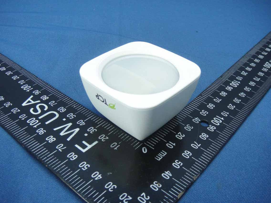
Z3M-GSYP1J11
Jul 14, 2014Wireless Motion Sensor
Equipment Class
DTS - Digital Transmission System
Z3M-GUBW1J1
Apr 28, 2014Lighting Gateway
Equipment Class
DTS - Digital Transmission System
Z3M-ZBMOD1
Jan 16, 2014Zigbee Wireless Module
Equipment Class
DTS - Digital Transmission System
Z3M-JENMOD1
Jan 16, 2014Zigbee Wireless Module
Equipment Class
DTS - Digital Transmission System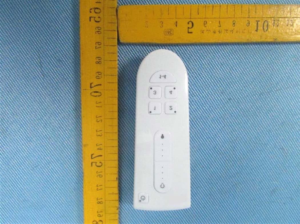
Z3M-GCM10
Feb 26, 2013LIGHTING CONTROLLER,JN,BUTTON,4CH
Equipment Class
DXX - Part 15 Low Power Communication Device Transmitter