Z9M-PAN-1-0WIRELESS CURRENT SENSOR
Panoramic Power ltd.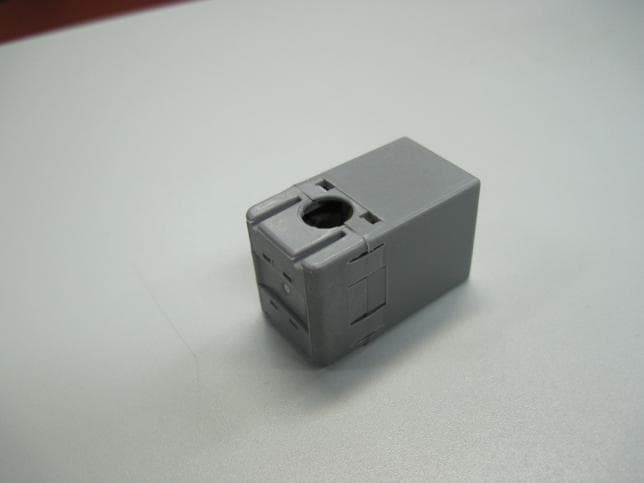
Click to zoom
Application Details
- Equipment Class
- DXX - Part 15 Low Power Communication Device Transmitter
- Date of Grant
- Dec 05, 2011
- Application Purpose
- Original Equipment
- Date of Application
- Dec 05, 2011
- Equipment Note
- WIRELESS CURRENT SENSOR
- Frequency Range
- 905.00000000 - 925.00000000
- Company
- Panoramic Power ltd.
- Country
- Israel
Documents & Files
Document Text
Text extracted from the exhibit documents filed with the FCC. Open a document above to read the original.
Users Manual
Panoramic Power System PAN-1-0Sensor InstallationGuide Energy Management System- Sensor Installation Guide Panoramic Power and P3E are trademarks of Panoramic Power Ltd. All other trademarks are the property of their respective owners. Our products are protected by patents pending as well as, when applicable, by copyrights2 Copyright Notice Copyright © 2011 Panoramic Power Ltd. All rights reserved. Energy Management System- Sensor Installation Guide Panoramic Power and P3E are trademarks of Panoramic Power Ltd. All other trademarks are the property of their respective owners. Our products are protected by patents pending as well as, when applicable, by copyrights3 Documented Releases Revision NumberRevision DescriptionRevision Date 1.0New versionOctober 2011 Energy Management System- Sensor Installation Guide Panoramic Power and P3E are trademarks of Panoramic Power Ltd. All other trademarks are the property of their respective owners. Our products are protected by patents pending as well as, when applicable, by copyrights4 Contents Overview..................................................................................................5 Unpacking the Hardware........................................................................5 Safety Precautions....................................................................................5 Hardware Description.............................................................................6 Installing a Sensor....................................................................................7 Uninstalling a Sensor...............................................................................9 Sensor Specifications................................................................................9 Troubleshooting.....................................................................................11 Support...................................................................................................11 Energy Management System- Sensor Installation Guide Panoramic Power and P3E are trademarks of Panoramic Power Ltd. All other trademarks are the property of their respective owners. Our products are protected by patents pending as well as, when applicable, by copyrights5 Overview PanoramicPowerSystem (PPS) monitors electrical energy consumption at individual circuitleveland detects excess usage allowing organizationsto identifyandreduce energyand maintenanceexpenses. PPSconsists ofwireless, self-powered sensors engineered to allowfor rapid, non-invasive installation, withalmostno disturbancetooperations. Sensors are easily attached to circuit breakers by just snapping them on to theoutgoingelectricalwire.They monitor the flow of electricity through theresultingmagnetic field and also usethefieldasapower source.The sensors do not requireany maintenance. Data collected by the sensors is sent toabridge, which, in turn, transfers the information to thePPS server through the Internet, using Cloud technology. The sensors report the energyconsumption to thebridgeat sub-minute intervals.Consumption reports can be retrieved through thesystem. This user guide explains how to install the sensors. Unpacking the Hardware Sensors are shipped in30-unit packs. The package includes the following items: 30sensors. 1 sensor opener Safety Precautions The sensor must be installed only on an insulated conductor. The conductor’s diameter and maximumcurrentmust match the specification printed on thesensor. The sensor should be installed and removedonlyby a qualified electrician. Energy Management System- Sensor Installation Guide Panoramic Power and P3E are trademarks of Panoramic Power Ltd. All other trademarks are the property of their respective owners. Our products are protected by patents pending as well as, when applicable, by copyrights6 Installation must not be performed on a live wire for reasons of safety and random shock hazard.Power supply to the panel must be shut off before andduring installation. Thesensor must not be installed lying or touching busbars or any other non-insulated, exposed conductors. Installation is possible both on external entry/exit conductors before the terminal strip,as well as both ends of the circuit breaker. The least cramped, most accessible location should be chosen for installation.The sensor should be installed such that the arrow points in the direction of the load. Hardware Description This procedure must be carried outonlyby a certified electrician. The sensors are shipped closed,in orderto protect thecore from dust and other pollutants. Opena sensor only whenpreparingtoinstallit. Figure1. Closed sensorFigure2. Open sensor:Core Energy Management System- Sensor Installation Guide Panoramic Power and P3E are trademarks of Panoramic Power Ltd. All other trademarks are the property of their respective owners. Our products are protected by patents pending as well as, when applicable, by copyrights7 The sensor comes with a label fixedon it, containingaunique ID. Figure3. Open sensor:Label Sensors are mapped tobuildingcircuits according to their ID, so that circuitconsumption data is associated with the correct sensor. Installing a Sensor To installa sensor, followthese steps: 1.Make sure the 4 core surfaces are free of dust or any other particles. If necessary, wipe it with a dry cloth (the core is clean when it is first opened and this measure may be redundant). 2.Open the cover of the electrical panel board. 3.Make sure you have a plan that indicates the circuits to be monitored and the sensor IDs associates with each such circuit. Identify the circuit breaker on which you would like to install the sensor. The ID appears on the label fixed to the sensor. 4.Pick a sensor and slideit intotheOpener from the labeledside towards thecover. Energy Management System- Sensor Installation Guide Panoramic Power and P3E are trademarks of Panoramic Power Ltd. All other trademarks are the property of their respective owners. Our product…
Text truncated - open the document above for the full version.
ID Label/Location Info
14.49mm 12.55mm 4R0.5mm PANTONE C 1:1 3:1 14.49mm 12.55mm 4R0.5mm PANTONE C
Operational Description
Operational DescriptionWireless current sensor FCC ID:Z9M-PAN-1-0 The product is asensor which is located on the Building Branch Circuit to detect the current supplied. It is a compact, plastic encased unit, not directly connected to the electrical supply source but is mutually electromagnetically coupled to derive its electrical supply from the utility wiring. It uses internal step-down transformer for that coupling and supplying the circuits, to achieve low voltage for circuits needed for the measurement
Test Report
Test Report E109690.00 Panoramic Power Ltd. Page 1 of 32 ITL FCCMASVE 1.25 26 March 2003 DATE: 22 November 2011 I.T.L. (PRODUCT TESTING) LTD. FCC Radio Test Report for Panoramic Power Ltd. Equipment under test: Wireless Self-Powered Branch- Circuit Level Current Sensor PAN-1-1-063-US Written by: ____________________________ Y. Feldman, Documentation Approved by: _____________________________ A. Sharabi, Test Engineer Approved by: _____________________________ I. Raz, EMC Laboratory Manager This report must not be reproduced, except in full, without the written permission of I.T.L. (Product Testing) Ltd. This report relates only to items tested. Test Report E109690.00 Panoramic Power Ltd. Page 2 of 32 ITL FCCMASVE 1.25 26 March 2003 Measurement/Technical Report for Panoramic Power Ltd. Equipment under test: Wireless Self-Powered Branch-Circuit Level Current Sensor FCC ID: Z9M-PAN-1-0 This report concerns: Original Grant: x Class I change: Class II change: 47CFR15 Section 15.249 Measurement procedure used is ANSI C63.4-2003. Application for Certification Applicant for this device: prepared by: (different from "prepared by") Ishaiahou Raz Adi Shamir ITL (Product Testing) Ltd. Panoramic Power Ltd. Kfar Bin Nun 20 Atir Yeda St. D.N. Shimshon 99780 Kfar Saba, 44643 Israel Israel Tel: +972-8-918-6117 Tel: 972-9-766-7600 Fax: +972-8-915-3101 Fax: 972-9-766-7610 Email: [email protected] Email: [email protected] TABLE OF CONTENTS 1. GENERAL INFORMATION ------------------------------------------------------------------------------- 4 1.1 Administrative Information ................................................................................. 4 1.2 List of Accreditations ......................................................................................... 5 1.3 Product Description ........................................................................................... 6 1.4 Test Methodology .............................................................................................. 6 1.5 Test Facility ....................................................................................................... 6 1.6 Measurement Uncertainty ................................................................................. 6 2. SYSTEM TEST CONFIGURATION --------------------------------------------------------------------- 7 2.1 Justification ........................................................................................................ 7 2.2 Special Accessories .......................................................................................... 7 2.3 Equipment Modifications ................................................................................... 7 2.4 Configuration of Tested System ........................................................................ 7 3. RADIATED MEASUREMENTS TEST SETUP PHOTOS ----------------------------------------- 8 4. FIELD STRENGTH OF FUNDAMENTAL ------------------------------------------------------------- 9 4.1 Test Specification .............................................................................................. 9 4.2 Test Procedure .................................................................................................. 9 4.3 Test Results....................................................................................................... 9 4.4 Test Instrumentation Used, Field Strength of Fundamental ........................... 14 5. SPURIOUS RADIATED EMISSION 9 KHZ - 30 MHZ --------------------------------------------- 15 5.1 Test Specification ............................................................................................ 15 5.2 Test Procedure ................................................................................................ 15 5.3 Test results ...................................................................................................... 15 5.4 Test Instrumentation Used, Radiated Measurements 9 kHz – 30 MHz .......... 16 5.5 Field Strength Calculation ............................................................................... 16 6. SPURIOUS RADIATED EMISSION 30 MHZ- 10 GHZ -------------------------------------------- 17 6.1 Test Specification ............................................................................................ 17 6.2 Test Procedure ................................................................................................ 17 6.3 Test Results..................................................................................................... 17 6.4 Test Instrumentation Used, Radiated Measurements 30 MHz – 10 GHz ....... 20 6.5 Field Strength Calculation ............................................................................... 20 7. BAND EDGE ATTENUATION -------------------------------------------------------------------------- 21 7.1 Test Specification ............................................................................................ 21 7.2 Test Procedure ................................................................................................ 21 7.3 Test Results..................................................................................................... 21 7.4 Test Instrumentation Used, Band Edge Attenuation ....................................... 25 8. APPENDIX A - CORRECTION FACTORS ---------------------------------------------------------- 26 8.1 Correction factors for CABLE ......................................................................... 26 8.2 Correction factors for CABLE ......................................................................... 27 8.3 Correction factors for CABLE ......................................................................... 28 12.6 Correction factors for LOG PERIODIC ANTENNA ........................................ 29 8.4 Correction factors for LOG PERIODIC ANTENNA ........................................ 30 8.5 Correction factors for BICONICAL ANTENNA ..................................…
Text truncated - open the document above for the full version.
Contact Information
Applicant
Yael Alali(Hardware Team Leader)
Test Firm
Israel Testing LaboratoriesIIan Cohen
Technical Specifications
| # | Rule Parts | Frequency Range | Power Output |
|---|---|---|---|
| 1 | 15C | 905 MHz - 925 MHz | - |
Other Applications from Panoramic Power ltd.
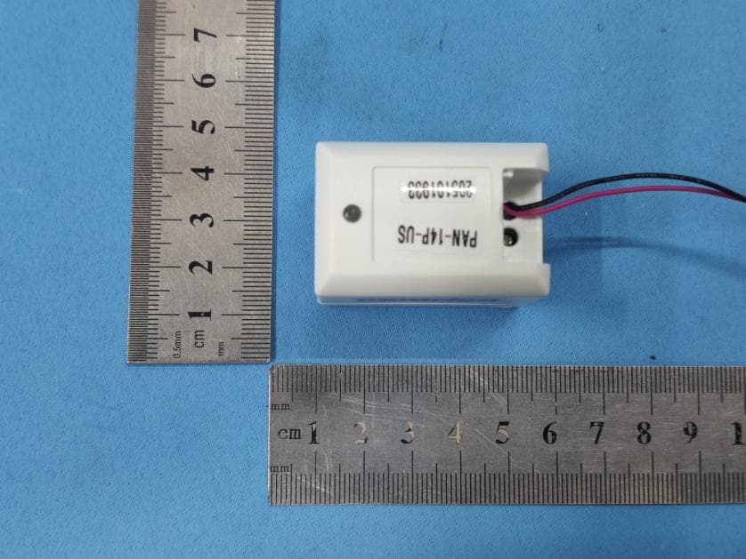
Z9M-PAN14P
Feb 09, 2021Wireless High Current Sensor with Power Measurement Ability
Equipment Class
DXX - Part 15 Low Power Communication Device Transmitter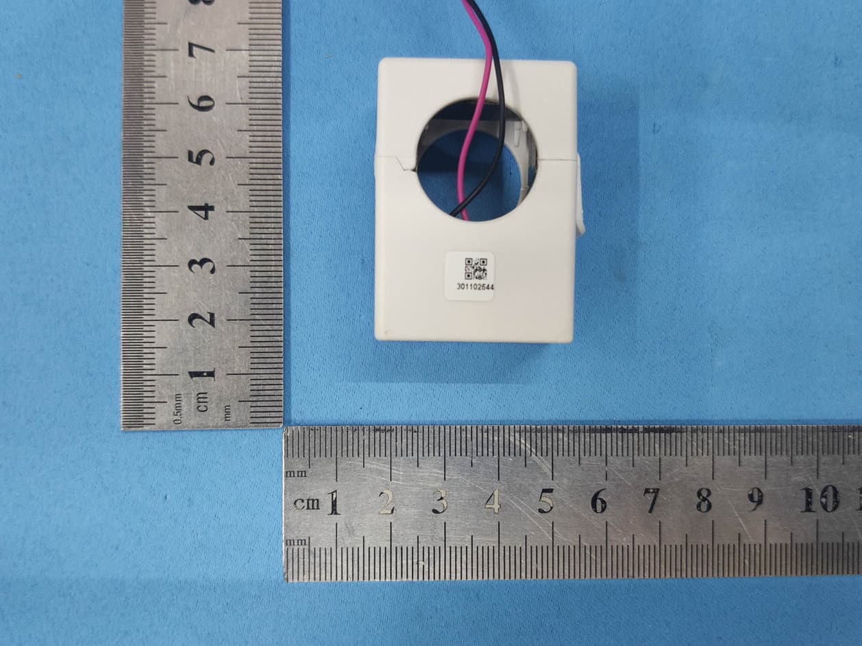
Z9M-PAN12P
Jan 06, 2021200A Wireless Current Sensor with Power Measurement Ability
Equipment Class
DXX - Part 15 Low Power Communication Device Transmitter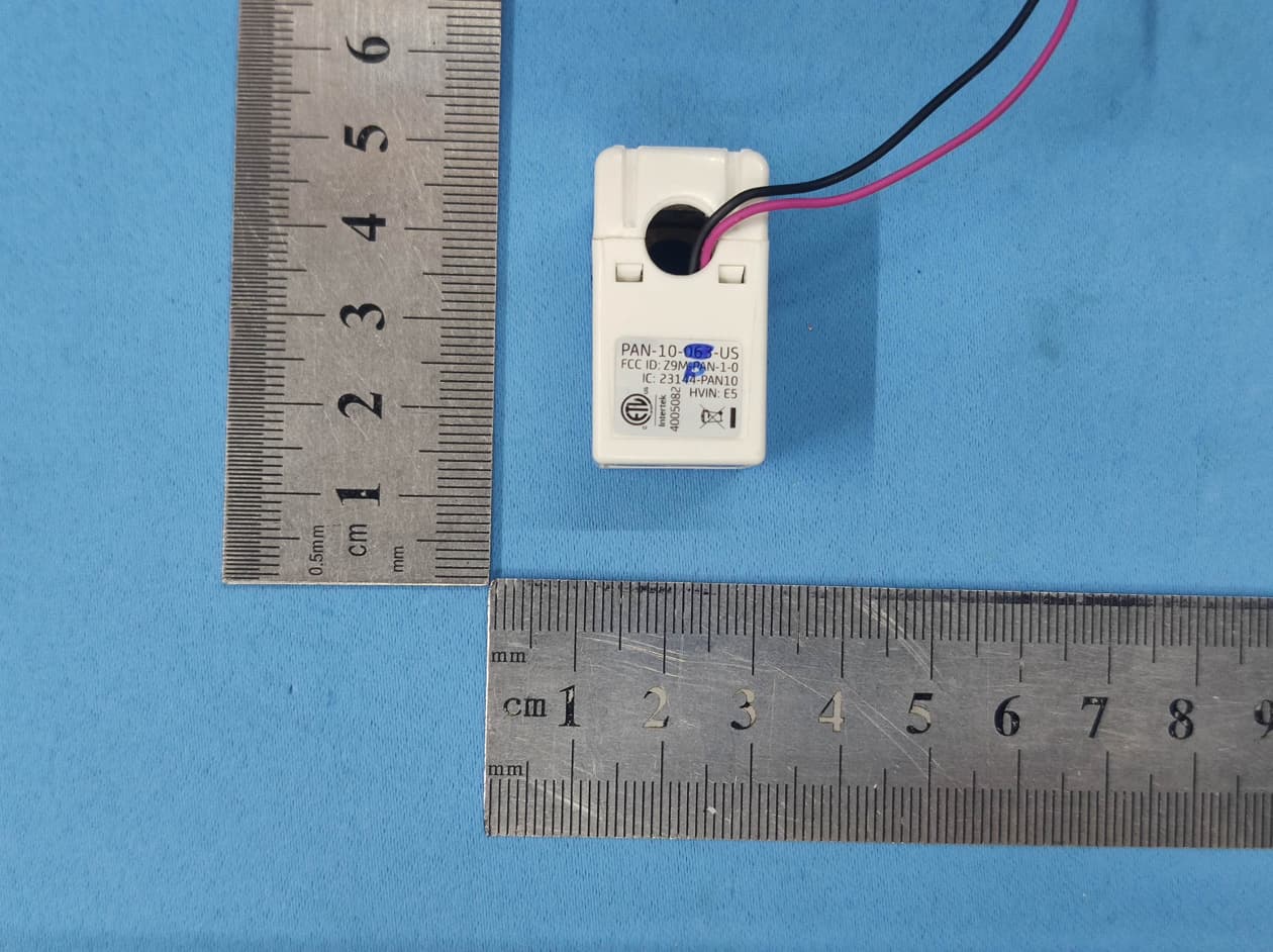
Z9M-PAN10P
Jan 05, 202163A Wireless Current Sensor with Power Measurement Ability
Equipment Class
DXX - Part 15 Low Power Communication Device Transmitter
Z9M-PAN-4-2
Jun 08, 2014Wireless Power Sensor PAN-42
Equipment Class
DXX - Part 15 Low Power Communication Device Transmitter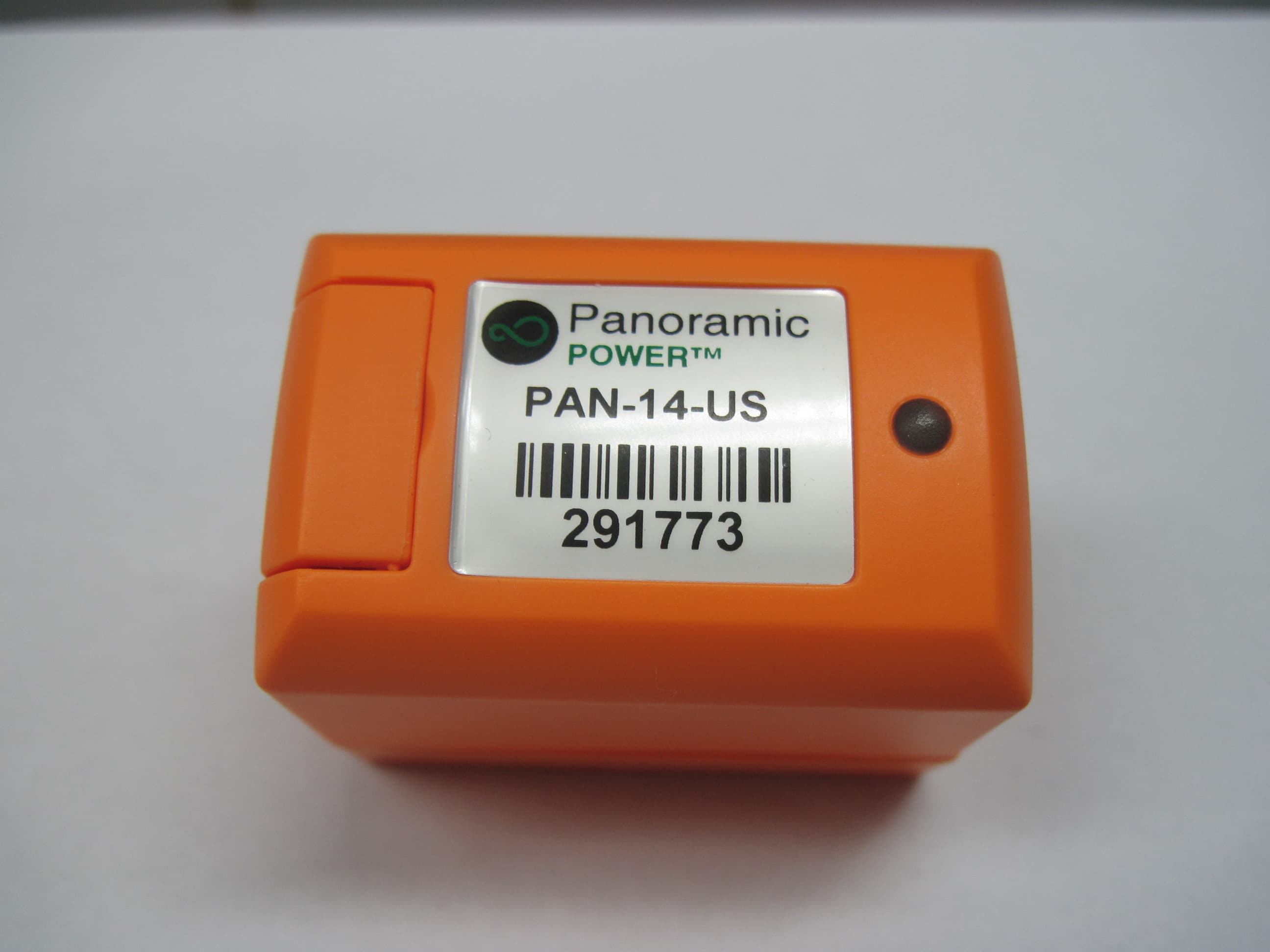
Z9M-PAN-1-4
May 26, 2014High Current Wireless Sensor PAN-14-US
Equipment Class
DXX - Part 15 Low Power Communication Device Transmitter