Z9M-PAN14PWireless High Current Sensor with Power Measurement Ability
Panoramic Power ltd.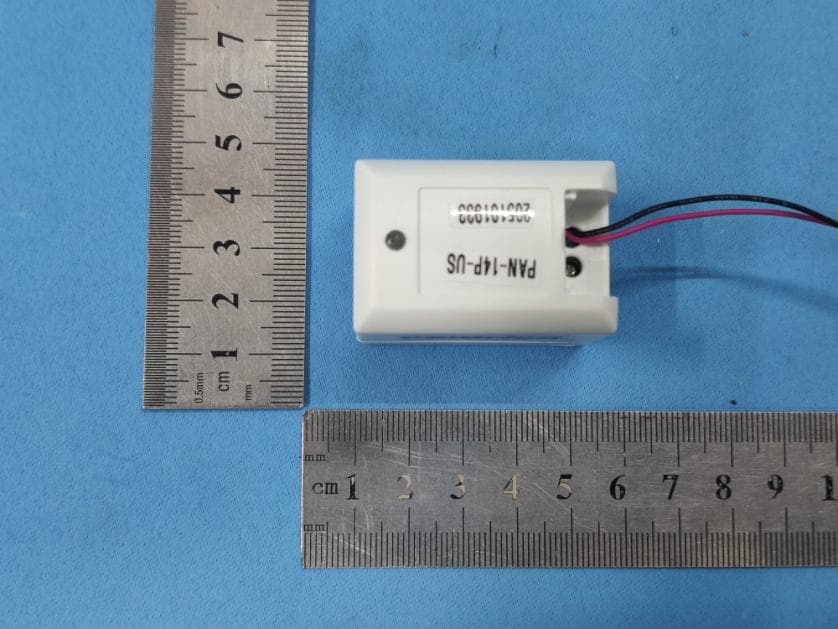
Click to zoom
Application Details
- Equipment Class
- DXX - Part 15 Low Power Communication Device Transmitter
- Date of Grant
- Feb 09, 2021
- Application Purpose
- Original Equipment
- Date of Application
- Feb 08, 2021
- Equipment Note
- Wireless High Current Sensor with Power Measurement Ability
- Frequency Range
- 915.00000000 - 915.00000000
- Company
- Panoramic Power ltd.
- Country
- Israel
Documents & Files
Document Text
Text extracted from the exhibit documents filed with the FCC. Open a document above to read the original.
Users Manual
Wireless electricity sensor familyoverview Minimum operating current 0.03 – 0.05 A (at input from external CT) Transmission interval Our electricity sensor series is comprised of non-invasive, self-powered, miniature wireless current sensors. The sensors clamp onto the electrical outgoing wire from thecircuitbreakerandare self-poweredbythe circuit’smagneticfield.Hundreds of sensors canbe installed ina few hourswith nodisturbance to daily operations. Once installed, the sensors become part of the building infrastructure, never requiring maintenance, service or batteryreplacement. PAN-14P wireless high current sensor specifications Current input range 0 – 5 A (up to 10 A peak) (fromexternal currenttransformer) The PAN-14P high-current sensor attaches to any size standard 0 – 5 Acurrent transformer, allowing measurements at any current range or wire gauge. Current measurement accuracy Typically <2% at I > 0.1 A (at input from external CT) AC frequency supported Transmission frequency Transmission power (ERP) 60 Hz 915 MHz 0 dBm (max) 10 seconds 33.8 × 29 × 42.5 mm 1.33 × 1.14 × 1.67 inch Physical dimensions Current measurement range Determined by external current transformer Wireless electricity sensor familyoverview specifications Operating humidity range 5% – 95% non-condensing PAN-14P wireless high current sensor Flammability rating of external enclosure UL94 V-0 Key features • Connects to any standard 5 A current transformer • No maintenance; self-powered • High accuracy • Wireless sensor and CT are closedaround the hot wire with no additional wiring • Real-time current data transmitted every 10seconds Operating temperature -25 – 60°C / -13 – 140°F Storage temperature -25 – 65°C / -13 – 149°F Ingress protection (IP) rating IP5X CB Certification IEC 61010-1, IEC 61010-2-030 by Intertek Testing Services USA and Canada Safety: UL 61010-1, UL 61010-2-030, CAN/CSA-C22.2 No. 61010-1 (ETL listed) EMC: FCC Part 15 subpart B, ICES-003 Radio: FCC Part 15 subpart C, RSS-210, RSS-Gen Europe Safety: EN 61010-1, EN 61010-2-030 (CE) EMC: EN ETSI 301 489-1, 301 489-3, 613 326-1 Radio: EN ETSI 300 220-1, 300 220-2 Australia ACMA compliant Russia EAC compliant Japan Radio: ARIB STD-T108 Certification 1 Wireless electricity sensor familyoverview FCC Warnings Modifications not expressly approved by the manufacturer could void the user's authority to operate the equipment under FCC Rules. ISED Warning (Modification statement) Panoramic Power n’approuve aucune modification apportée à l’appareil par l’utilisateur, quelle qu’en soit la nature. Tout changement ou modification peuvent annuler le droit d’utilisation de l’appareil par l’utilisateur. RF Exposure Warnings Mobile Device RF Exposure Statement Statement in UM RF Exposure - This device is only authorized for use in a mobile application. At least 20 cm of separation distance between the PAN-14-P Sensors and the user's body must be maintained at all times. Interference statement This device complies with Part 15 of the FCC Rules and Industry Canada licence-exempt RSS standard(s). Operation is subject to the following two conditions: (1) this device may not cause interference, and (2) this device must accept any interference, including interference that may cause undesired operation of the device. Le présent appareil est conforme aux CNR d'Industrie Canada applicables aux appareils radio exempts de licence. L'exploitation est autorisée aux deux conditions suivantes : (1) l'appareil ne doit pas produire de brouillage, et (2) l'utilisateur de l'appareil doit accepter tout brouillage radioélectrique subi, même si le brouillage est susceptible d'en compromettre le fonctionnement. Wireless notice This device complies with FCC/ISED radiation exposure limits set forth for an uncontrolled environment and meets the FCC radio frequency (RF) Exposure Guidelines and RSS‐102 of the ISED radio frequency (RF) Exposure rules. This transmitter must not be co-located or operating in conjunction with any other antenna or transmitter. Le présent appareil est conforme à l'exposition aux radiations FCC / ISED définies pour un environnement non contrôlé et répond aux directives d'exposition de la fréquence de la FCC radiofréquence (RF) et RSS‐102 de la fréquence radio (RF) ISED règles d'exposition. L'émetteur ne doit pas être colocalisé ni fonctionner conjointement avec à autre antenne ou autre émetteur. Wireless electricity sensor familyoverview Statement according to FCC part 15.105: This equipment has been tested and found to comply with the limits for a Class B digital device, pursuant to Part 15 of the FCC Rules. These limits are designed to provide reasonable protection against harmful interference in a residential installation. This equipment generates uses and can radiate radio frequency energy and, if not installed and used in accordance with the instructions, may cause harmful interference to radio communications. However, there is no guarantee that interference will not occur in a particular installation. If this equipment does cause harmful interference to radio or television reception, which can be determined by turning the equipment off and on, the user is encouraged to try to correct the interference by one or more of the following measures: -- Reorient or relocate the receiving antenna. -- Increase the separation between the equipment and receiver. -- Connect the equipment into an outlet on a circuit different from that to which the receiver is connected. -- Consult the dealer or an experienced radio/TV technician for help. Statement according to FCC part 15.19: This device complies with part 15 of the FCC Rules. Operation is subject to the following two conditions: (1) This device may not cause harmful interference, and (2) this device must accept any interference received, including interference that may cause undesired operation. Statement according to FCC part 15.21: Changes or modifications not expressly approved by the party responsible for compliance could…
Text truncated - open the document above for the full version.
Cover Letter(s)
DATE : 2021-01-19 Equipment Autorisation Division Federal Communications Commission 7435 Oakland Mills Road Columbia, MD 21046 FCC ID: Z9M-PAN14P Product Name: Wireless High Current Sensor with Power Measurement Ability Request for Confidentiality To Whom It May Concern, Pursuant to the provisions of the Commission’s rules Title 47 Sections §0.457 and §0.459, we are requesting the Commission to withhold the following attachment(s) as confidential documents from public disclosure indefinitely. These documents contain detailed system and equipment descriptions and are considered as proprietary information in operation of the equipment. The public disclosure of these documents might be harmful to our company and would give competitors an unfair advantage in the market. Schematic Diagram Block Diagram Operational Description In additional to above mentioned documents, in order to comply with the marketing regulations in Title 47 CFR §2.803 and the importation rules in Title 47 CFR §2.1204, while ensuring that business sensitive information remains confidential until the actual marketing of newly authorized devices, we request Short Term Confidentiality of the following attachment(s); External Photos Test Setup Photos Internal Photos User Manual For 45 days, pursuant to Public Notice DA 04-1705. OR For 180 days pursuantto KDB 726920 D01. It is our understanding that all measurement test reports, FCC ID label format and correspondence during the certification review process cannot be granted as confidential documents and this information will be available for public review once the grant of equipment authorization is issued. Signature: Name: Yael Alali Title: Hardware Team Leader Company: Panoramic Power ltd.
Cover Letter(s)
DATE : 2021-01-19 Federal Communications Commission Authorization & Evaluation Division 7345 Oakland Mills Road Columbia, Maryland 21046 Authority to Act as Agent On our behalf, I appoint Jason Wu of Global United Technology Services Co., Ltd.and No. 123-128, Tower A, Jinyuan Business Building, No.2, Laodong Industrial Zone, Xixiang Road, Baoan District, Shenzhen, Guangdong, China to act as our agent in the preparation of this application for equipment certification. I certify that submitted documents properly describe the device or system for which equipment certification is sought. I also certify that each unit manufactured, imported or marketed, as defined in the Federal Communications Commission’s regulations will have affixed to it a label identical to that submitted for approval with this application. For instances where our authorized agent signs the application for certification on our behalf, I acknowledge that all responsibility for complying with the terms and conditions for certification, still resides with Panoramic Power ltd. and 15 Atir Yeda St., Kfar Saba, 4464312, Israel Signature: Name: Yael Alali Title: Hardware Team Leader Company: Panoramic Power ltd.
ID Label/Location Info
Label location
ID Label/Location Info
Model PAN-14P Rev.US: F1.0 Made In Israel by Panoramic Power Postal Address: 15 Atir Yeda St. Kfar Saba 4464312 Israel FCC ID: Z9M-PAN14P IC : 23144-PAN14P; HVIN: F1.0 CAN ICES-003 (A) 5A This device complies with Part 15 of the FCC Rules and Industry Canada licence-exempt RSS standard(s). Operation is subject to the following two conditions: (1) this device may not cause interference, and (2) this device must accept any interference, including interference that may cause undesired operation of the device. . Le présent appareil est conforme aux CNR d'Industrie Canada applicables aux appareils radio exempts de licence. L'exploitation est autorisée aux deux conditions suivantes : (1) l'appareil ne doit pas produire de brouillage, et (2) l'utilisateur de l'appareil doit accepter tout brouillage radioélectrique subi, même si le brouillage est susceptible d'en compromettre le fonctionnement. MAC: XX:XX:XX:XX:XX:XX S/N: XX:XX:XX:XX:XX:XX
RF Exposure Info
RFExposureevaluation Accordingto447498D01GeneralRFExposureGuidancev05 The1-gand10-gSARtestexclusionthresholdsfor100MHzto6GHzat testseparationdistances≤50mmaredeterminedby: [(max.powerofchannel,includingtune-uptolerance,mW)/(min.test separationdistance,mm)]·[√f(GHz)]≤3.0for1-gSARand≤7.5for 10-gextremitySAR,where f(GHz)istheRFchanneltransmitfrequencyinGHz PoweranddistanceareroundedtothenearestmWandmmbefore calculation Theresultisroundedtoonedecimalplaceforcomparison eirp=ptxgt=(EXd) 2 /30 where: pt=transmitteroutputpowerinwatts, gt=numericgainofthetransmittingantenna(unitless), E=electricfieldstrengthinV/m,---10 ((dBuV/m)/20) /10 6 d=measurementdistanceinmeters(m)---3m Sopt=(EXd) 2 /30xgt Antgain=-12dBi;soAntnumericgain=0.0631 Fieldstrength=73.08dBuV/m@3m SoPt={[10 (73.08/20) /10 6 x3] 2 /30x0.0631}x1000mW=0.0966mW So(0.0966mW/5mm)x√0.915GHz=0.0185<3 ThenSARevaluationisnotrequired
Test Report
Global United Technology Services Co., Ltd. Report No.: GTS202010000064-01 Authorized Signature: Robinson Luo Laboratory Manager This results shown in this test report refer only to the sample(s) tested, this test report cannot be reproduced, except in full, without prior written permission of the company. The report would be invalid without specific stamp of test institute and the signatures of compiler and approver. Page 1 of 19 TEST REPORT Applicant: FCC ID: Panoramic Power ltd. IC: Panoramic Power Ltd. Address of Applicant: FCC ID: 15 Atir Yeda St., Kfar Saba, 4464312, Israel IC: Atir Yeda St 15 Kfar Saba 4464312 Israel Manufacturer: Panoramic Power Ltd. Address of Manufacturer: 15 Atir Yeda St., Kfar Saba, 4464312, Israel Factory: USR Electronic Systems Ltd. Address of Factory: 14 Hartom St.Jerusalem 9777514, Israel Equipment Under Test (EUT) Product Name: Wireless High Current Sensor with Power Measurement Ability Model No.: PAN-14P-US HVIN: F1.0 FCC ID: Z9M-PAN14P IC: 23144-PAN14P Applicable standards: FCC CFR Title 47 Part 15 Subpart C Section 15.249 RSS-Gen Issue 5 RSS-210 Issue 10 Date of sample receipt: October 16, 2020 Date of Test: October 16, 2020-January 19, 2021 Date of report issued: January 19, 2021 Test Result : PASS * * In the configuration tested, the EUT complied with the standards specified above. Report No.: GTS202010000064-01 Page 2 of 19 2 Version Version No. Date Description 00 January 19, 2021 Original Prepared By: Date: January 19, 2021 Project Engineer Check By: Date: January 19, 2021 Reviewer Report No.: GTS202010000064-01 Page 3 of 19 3 Contents Page 1 COVER PAGE ............................................................................................................................................ 1 2 VERSION .................................................................................................................................................. 2 3 CONTENTS .............................................................................................................................................. 3 4 TEST SUMMARY ..................................................................................................................................... 4 5 GENERAL INFORMATION ...................................................................................................................... 5 5.1 GENERAL DESCRIPTION OF EUT ......................................................................................................... 5 5.2 TEST MODE ........................................................................................................................................ 6 5.3 DESCRIPTION OF SUPPORT UNITS ....................................................................................................... 6 5.4 DEVIATION FROM STANDARDS ............................................................................................................. 6 5.5 ABNORMALITIES FROM STANDARD CONDITIONS ................................................................................... 6 5.6 TEST FACILITY .................................................................................................................................... 6 5.7 TEST LOCATION ................................................................................................................................. 6 5.8 ADDITIONAL INSTRUCTIONS ................................................................................................................. 6 6 TEST INSTRUMENTS LIST ..................................................................................................................... 7 7 TEST RESULTS AND MEASUREMENT DATA ...................................................................................... 9 7.1 ANTENNA REQUIREMENT ..................................................................................................................... 9 7.2 CONDUCTED EMISSIONS ................................................................................................................... 10 7.3 RADIATED EMISSION METHOD ........................................................................................................... 13 7.3.1 Field Strength of The Fundamental Signal and spurious emissions ......................................... 15 7.3.2 Spurious emissions .................................................................................................................... 15 7.4 20DB OCCUPY BANDWIDTH AND 99% OCCUPIED BANDWIDTH ........................................................... 18 8 TEST SETUP PHOTO ............................................................................................................................ 19 9 EUT CONSTRUCTIONAL DETAILS ..................................................................................................... 19 Report No.: GTS202010000064-01 Page 4 of 19 4 Test Summary Test Item Section Result Antenna requirement 15.203 RSS-Gen Section 6.8 Pass AC Power Line Conducted Emission 15.207 RSS-Gen Section 8.8 Pass Field strength of the fundamental signal 15.249 (a) RSS-210 B10(a) Pass Spurious emissions 15.249 (a) (d)/15.209 RSS-Gen Clause 8.9&8.10 Pass Band edge 15.249 (d)/15.205 RSS-Gen Clause 8.9&8.10 Pass 20dB Occupied Bandwidth and 99% Occupied Bandwidth 15.215 (c) RSS-Gen 6.7 Pass Pass: The EUT complies with the essential requirements in the standard. Remark: Test according to ANSI C63.10: 2013 and ANSI C63.4: 2014. Measurement Uncertainty Test Item Frequency Range Measurement Uncertainty Notes Radiated Emission 30MHz-200MHz 3.8039dB (1) Radiated Emission 200MHz-1GHz 3.9679dB (1) Radiated Emission 1GHz-18GHz 4.29dB (1) Radiated Emission 18GHz-40GHz 3.30dB (1) AC Power Line Conducted Emission 0.15MHz ~ 30MHz 3.44dB (1) Note (1): The measurement uncertainty is for coverage factor of k=2 and a level of confidence of 95%. Report No.: GTS202010000064-01 Page 5 of 19 5 General Information 5.1 General Description of EUT P…
Text truncated - open the document above for the full version.
Test Setup Photos
Radiated Emission Conducted Emission
Contact Information
Applicant
Yael Alali(Hardware Team Leader)
Test Firm
Global United Technology Services Co. Ltd.Robinson Lo
Technical Specifications
| # | Rule Parts | Frequency Range | Power Output |
|---|---|---|---|
| 1 | 15C | 915 MHz - 915 MHz | - |
Other Applications from Panoramic Power ltd.
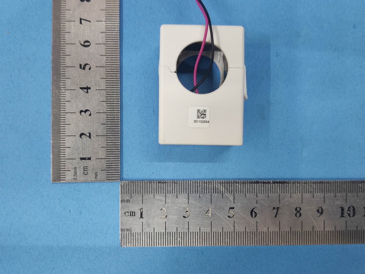
Z9M-PAN12P
Jan 06, 2021200A Wireless Current Sensor with Power Measurement Ability
Equipment Class
DXX - Part 15 Low Power Communication Device Transmitter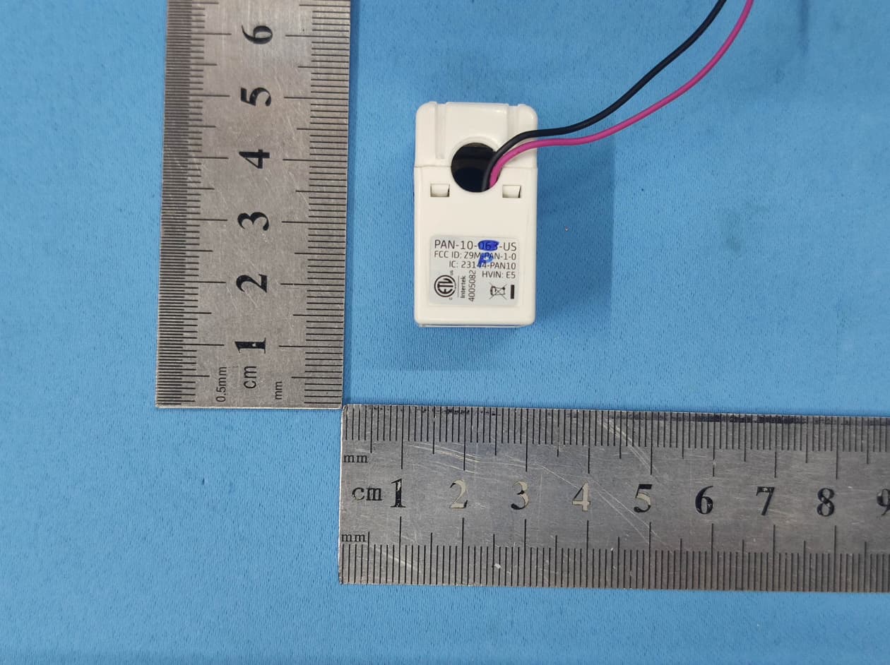
Z9M-PAN10P
Jan 05, 202163A Wireless Current Sensor with Power Measurement Ability
Equipment Class
DXX - Part 15 Low Power Communication Device Transmitter
Z9M-PAN-4-2
Jun 08, 2014Wireless Power Sensor PAN-42
Equipment Class
DXX - Part 15 Low Power Communication Device Transmitter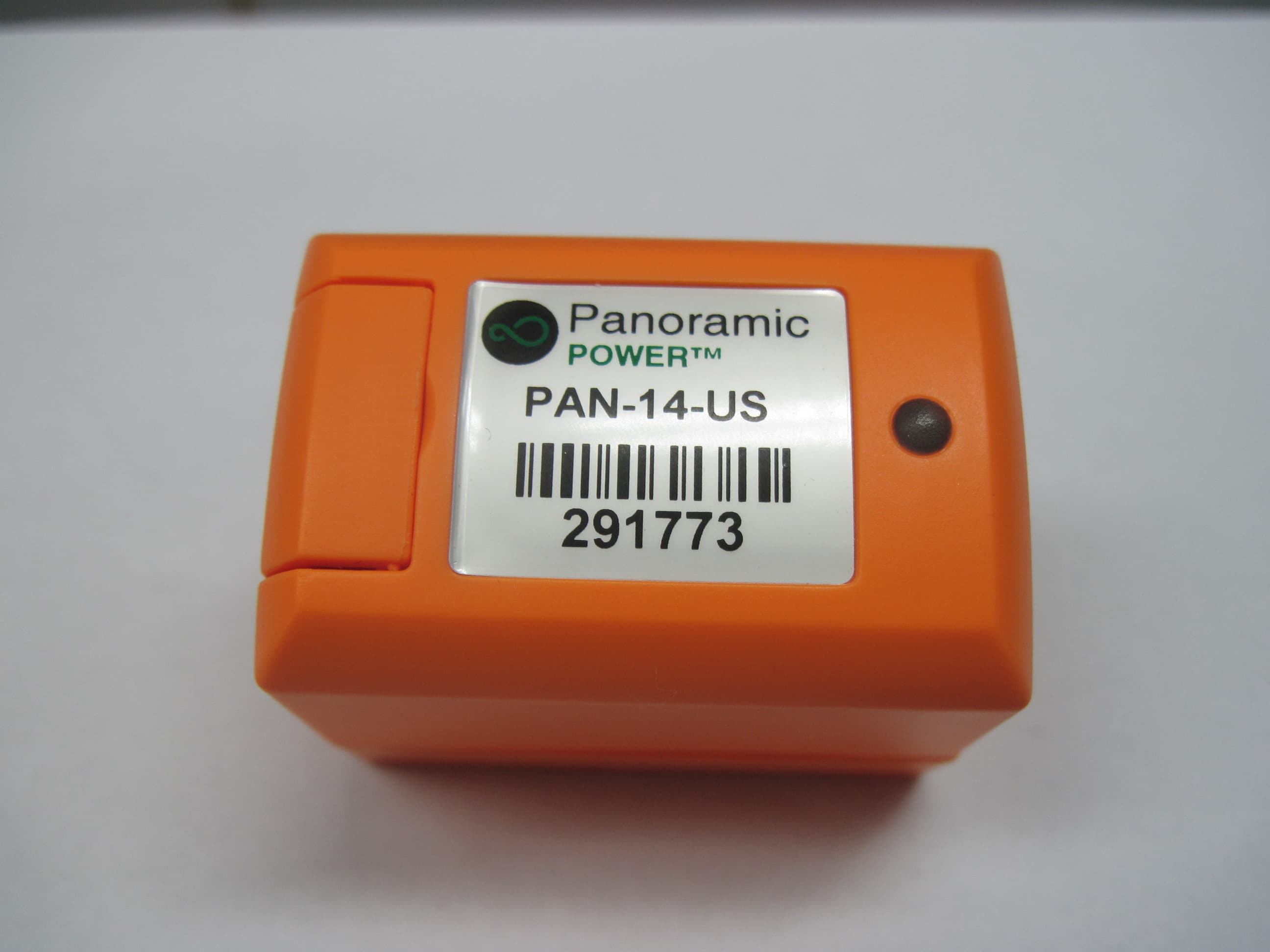
Z9M-PAN-1-4
May 26, 2014High Current Wireless Sensor PAN-14-US
Equipment Class
DXX - Part 15 Low Power Communication Device Transmitter
Z9M-PAN-1-2
Jul 31, 2012WIRELESS CURRENT SENSOR
Equipment Class
DXX - Part 15 Low Power Communication Device Transmitter