Z9M-PAN-1-4High Current Wireless Sensor PAN-14-US
Panoramic Power ltd.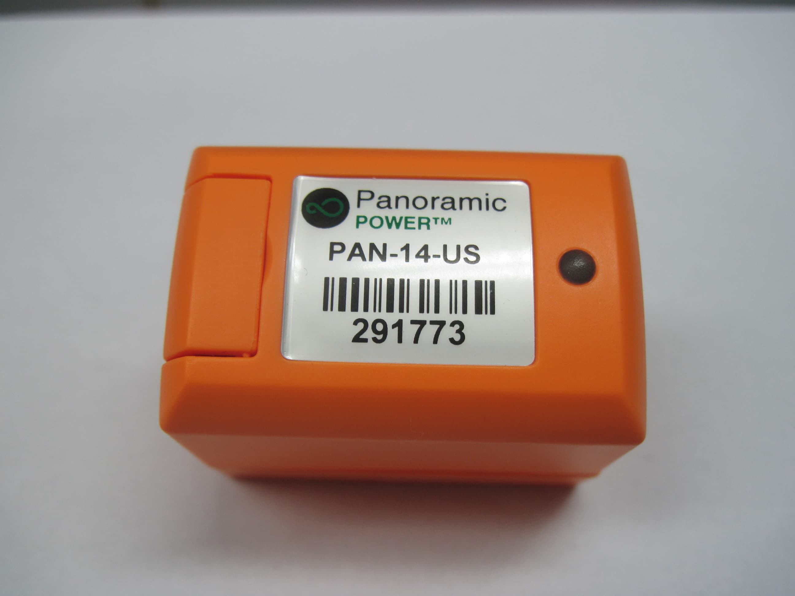
Click to zoom
Application Details
- Equipment Class
- DXX - Part 15 Low Power Communication Device Transmitter
- Date of Grant
- May 26, 2014
- Application Purpose
- Original Equipment
- Date of Application
- May 26, 2014
- Equipment Note
- High Current Wireless Sensor PAN-14-US
- Frequency Range
- 915.00000000 - 915.00000000
- Company
- Panoramic Power ltd.
- Country
- Israel
Documents & Files
Document Text
Text extracted from the exhibit documents filed with the FCC. Open a document above to read the original.
Users Manual
Panoramic Power System PAN-14 User Guide PAN-14 Sensor Installation Guide 2 Copyright Notice Copyright © 2014 Panoramic Power Ltd. All rights reserved. FCC Compliance Statement This device has been tested and found to comply with the limits for a Class B digital device, pursuant to Part 15 of the FCC Rules. These limits are designed to provide reasonable protection against harmful interference in residential installations. This equipment generates uses and can radiate radio frequency energy and, if not installed and used in accordance with the instructions, may cause harmful interference to radio and television reception. However, there is no guarantee that interference will not occur in a particular installation. If this device does cause such interference, which can be verified by turning the device off and on, the user is encouraged to eliminate the interference by one or more of the following measures: Re-orient or re-locate the receiving antenna. Increase the distance between the device and the receiver. Connect the device to an outlet on a circuit different from the one that supplies power to the receiver. Consult the dealer or an experienced radio/TV technician. WARNING! Changes or modifications to this unit not expressly approved by the party responsible for compliance could void the user’s authority to operate the equipment. This device complies with Part 15 of the FCC Rules. Operation is subject to two conditions: (1) This device may not cause harmful interference, and (2) this device must accept any interference that may be received or that may cause undesired operation. PAN-14 Sensor Installation Guide 3 Contents Overview ................................................................................................................ 4 Workflow ................................................................................................................ 4 Unpacking the Hardware ..................................................................................... 5 Safety Precautions ................................................................................................. 5 Mapping the Site ................................................................................................... 5 Installing the Sensor .............................................................................................. 6 Registering the Installed Sensor .......................................................................... 7 Monitoring Sensor Activity ................................................................................. 8 Uninstalling a Sensor ............................................................................................ 8 Sensor Specifications ............................................................................................. 8 Certified CTs .......................................................................................................... 9 Troubleshooting .................................................................................................. 10 Support ................................................................................................................. 10 PAN-14 Sensor Installation Guide 4 Overview This user guide explains how to install the PAN-14 sensors. PAN 14 Current Sensor Current Transpformer (CT) Workflow Sensor installation consists of the following steps: 1. Map the circuits. See Panoramic Power Deployment Tool User Guide. 2. Physically attach the sensors and the CTs to the wires. S2 S1 PAN-14 Sensor Installation Guide 5 3. Monitors the proper functioning of the sensors. See Panoramic Power Deployment Tool User Guide. Unpacking the Hardware Sensors are shipped in 3-unit packs. CTs are not included and can be bought separately. Safety Precautions The sensor must be installed only on an insulated conductor. CTs output/secondary current must not exceed 5A. The sensor and CT should be installed and removed only by a qualified electrician. Installation must not be performed on a live wire for reasons of safety and random shock hazard. Power supply to the panel must be shut off before and during installation. The sensor and CT must not be installed lying or touching bus bars or any other non-insulated, exposed conductors. Installation is possible both on external entry/exit conductors before the terminal strip, as well as both ends of the circuit breaker. The least cramped, most accessible location should be chosen for installation. The sensor should be installed such that the arrow points in the direction of the load. Mapping the Site See Panoramic Power Deployment Guide. PAN-14 Sensor Installation Guide 6 Installing the Sensor This procedure must be carried out by a certified electrician. 1. Connect the PAN 14 sensor to the CT : 2. Connect the two CT's outputs to the PAN-14 sensor using a 1.0-4.0mm 2 (12- 17 AWG) wires as follows: a. Connect the PAN-14 sensor's terminal marked as "1" to the CT's terminal marked as "S1" or "X1" b. Connect the PAN-14 sensor's terminal marked as "2" to the CT's terminal marked as "S2" or "X2" 3. Mount the CT on the hot wire: a. If the CT is split-core: Close the CT on the hot wire by disconnecting its two parts, and closing them around the hot wire. b. If the CT is solid-core: Disconnect one of the ends of the hot wire from the panel, insert it through the CT, and then reconnect it to the panel. c. In both cases, make sure the CT is placed on the wire so that the direction of current flow on the wire is from the side marked "P1" or "H1" on the CT, to the side marked "P2" or "H2" on the CT. PAN-14 Sensor Installation Guide 7 Other used CT polarity markings are K for entry and L for exit or Load side (respectively P1 and P2). 4. Make sure the sensor's LED is blinking. 5. Finalize the PAN-14 sensor and the CT's position on the panel: - Maintain a reasonable distance between the CT and the sensor. - Place the PAN-14 sensor on the side that is closer to the…
Text truncated - open the document above for the full version.
Operational Description
Specifications PAN-14 Physical dimensions 33.8 × 29 × 42.5 mm 1.33 × 1.14 × 1.67 inch Current input range (from external current transformer) 0-5 A RMS (up to 10 A peak) Current measurement range Any applicable range based on CT ratio Current measurement accuracy (typical, at 25 o C) <2% at I > 2% of full-scale current Minimum operating current (at input from external current transformer) 0.03 – 0.05 A AC frequency supported 50 Hz (EU version) 60 Hz (US version) Transmission frequency 434 MHz (EU) 915 MHz (US) Transmission power (ERP)* 0 dBm (Max) Transmission interval 10 seconds Safety and EMC certificates* USA & Canada Safety: UL-61010-1, CSA-C22.2 (ETL listed) EMC/Radio: FCC Part 15 subpart B, C Europe Safety: EN-61010-1 (CE) EMC: EN-ETSI 301489-3, Radio: EN-ETSI 300220-1 Israel Safety: IS-61010-1 (IEC 61010-1 modified) Radio: MoC Approval Flammability rating of external enclosure UL94 V-0 Operating temperature 0 – 50° C Storage temperature -20 – 65° C *Pending certification testing Key Features •Connects to any standard 0-5A CT •No maintenance; self-powered (does not require battery) •High accuracy •Wireless – sensor & CT are closed around the hotwire with no additional wiring •Real-time high- frequency current data transmitted every 10 seconds Panoramic Power’s High Current Wireless Sensor The Panoramic Power sensor series is made up of non-invasive, self-powered, miniature wireless current sensors. The PAN-14 high-current sensor attaches to any size standard 0-5 A current transformer, allowing measurements at any current range or wire gauge. Hundreds of sensors can be installed in a few hours with no disturbance of daily operations. Powered by magnetic fields, the sensors become part of the building infrastructure, never requiring maintenance, service or battery replacement. PAN-14 mounted on an off-the-shelf CT
Test Report
Test Report E137921.00 Panoramic Power Ltd. Page 1 of 35 ITL FCCMASVE 1.25 26 March 2003 DATE: 26 March 2014 I.T.L. (PRODUCT TESTING) LTD. FCC Radio Test Report For Panoramic Power Ltd. Equipment under test: High Current Wireless Sensor PAN-14-US Written by: ____________________________ R. Pinchuck, Documentation Approved by: _____________________________ A. Sharabi, Test Engineer Approved by: _____________________________ I. Raz, EMC Laboratory Manager This report must not be reproduced, except in full, without the written permission of I.T.L. (Product Testing) Ltd. This report relates only to items tested. Test Report E137921.00 Panoramic Power Ltd. Page 2 of 35 ITL FCCMASVE 1.25 26 March 2003 Measurement/Technical Report for Panoramic Power Ltd. Equipment under test: High Current Wireless Sensor PAN-14-US FCC ID: Z9M-PAN-1-4 This report concerns: Original Grant: x Class I change: Class II change: Equipment Type: Digital Transmission System Limits used: 47CFR15 Section 15.249 Measurement procedure used is KDB 558074 D01 09 April 2013 and ANSI C63.4-2003. Application for Certification Applicant for this device: prepared by: (different from "prepared by") R Pinchuck Adi Shamir ITL (Product Testing) Ltd. Panoramic Power Ltd. Kfar Bin Nun 20 Atir Yeda St. D.N. Shimshon 99780 Kfar Saba, 44643 Israel Israel Tel: +972-8-918-6117 Tel: 972-9-766-7600 Fax: +972-8-915-3101 Fax: 972-9-766-7610 Email: [email protected] Email: [email protected] Test Report E137921.00 Panoramic Power Ltd. Page 3 of 35 ITL FCCMASVE 1.25 26 March 2003 TABLE OF CONTENTS 1. GENERAL INFORMATION ------------------------------------------------------------------------------- 4 1.1 Administrative Information ................................................................................. 4 1.2 List of Accreditations ......................................................................................... 5 1.3 Product Description ........................................................................................... 6 1.4 Test Methodology .............................................................................................. 6 1.5 Test Facility ....................................................................................................... 6 1.6 Measurement Uncertainty ................................................................................. 6 2. SYSTEM TEST CONFIGURATION --------------------------------------------------------------------- 7 2.1 Justification ........................................................................................................ 7 2.2 Special Accessories .......................................................................................... 7 2.3 Equipment Modifications ................................................................................... 7 2.4 Configuration of Tested System ........................................................................ 7 3. RADIATED MEASUREMENTS TEST SETUP PHOTOS ----------------------------------------- 8 4. FIELD STRENGTH OF FUNDAMENTAL ------------------------------------------------------------10 4.1 Test Specification ............................................................................................ 10 4.2 Test Procedure ................................................................................................ 10 4.3 Test Results..................................................................................................... 10 4.4 Test Instrumentation Used, Field Strength of Fundamental ........................... 14 5. SPURIOUS RADIATED EMISSION 9 KHZ - 30 MHZ ---------------------------------------------15 5.1 Test Specification ............................................................................................ 15 5.2 Test Procedure ................................................................................................ 15 5.3 Test results ...................................................................................................... 15 5.4 Test Instrumentation Used, Radiated Measurements 9 kHz – 30 MHz .......... 16 5.5 Field Strength Calculation ............................................................................... 16 6. SPURIOUS RADIATED EMISSION 30 MHZ- 10 GHZ --------------------------------------------17 6.1 Test Specification ............................................................................................ 17 6.2 Test Procedure ................................................................................................ 17 6.3 Test Results..................................................................................................... 17 6.4 Test Instrumentation Used, Radiated Measurements 30 MHz – 10 GHz ....... 20 6.5 Field Strength Calculation ............................................................................... 20 7. BAND EDGE ATTENUATION --------------------------------------------------------------------------21 7.1 Test Specification ............................................................................................ 21 7.2 Test Procedure ................................................................................................ 21 7.3 Test Results..................................................................................................... 21 7.4 Test Instrumentation Used, Band Edge Attenuation ....................................... 25 8. AVERAGE FACTOR CALCULATION ----------------------------------------------------------------26 8.1 Test Equipment Used, Average Factor Calculation ........................................ 28 9. APPENDIX A - CORRECTION FACTORS ----------------------------------------------------------29 9.1 Correction factors for CABLE ......................................................................... 29 9.2 Correction factors for CABLE ......................................................................... 30 9.3 Correction factors for CABLE ...............................…
Text truncated - open the document above for the full version.
Test Setup Photos
Radiated Measurements Test Setup Photos
Contact Information
Applicant
Yael Alali(Hardware Team Leader)
Test Firm
Israel Testing LaboratoriesIIan Cohen
Technical Specifications
| # | Rule Parts | Frequency Range | Power Output |
|---|---|---|---|
| 1 | 15C | 915 MHz - 915 MHz | - |
Other Applications from Panoramic Power ltd.
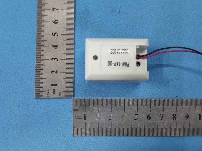
Z9M-PAN14P
Feb 09, 2021Wireless High Current Sensor with Power Measurement Ability
Equipment Class
DXX - Part 15 Low Power Communication Device Transmitter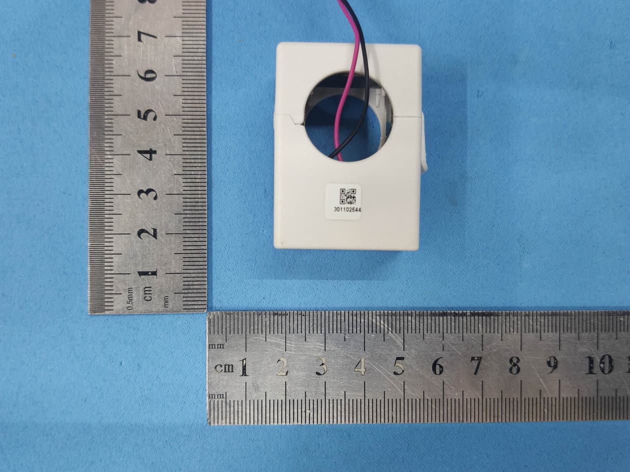
Z9M-PAN12P
Jan 06, 2021200A Wireless Current Sensor with Power Measurement Ability
Equipment Class
DXX - Part 15 Low Power Communication Device Transmitter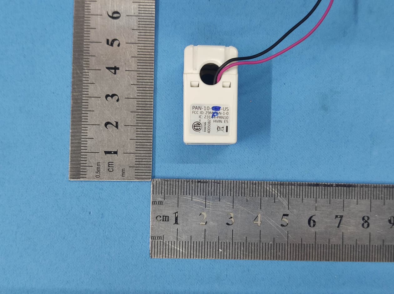
Z9M-PAN10P
Jan 05, 202163A Wireless Current Sensor with Power Measurement Ability
Equipment Class
DXX - Part 15 Low Power Communication Device Transmitter
Z9M-PAN-4-2
Jun 08, 2014Wireless Power Sensor PAN-42
Equipment Class
DXX - Part 15 Low Power Communication Device Transmitter
Z9M-PAN-1-2
Jul 31, 2012WIRELESS CURRENT SENSOR
Equipment Class
DXX - Part 15 Low Power Communication Device Transmitter