Z9M-PAN-4-2Wireless Power Sensor PAN-42
Panoramic Power ltd.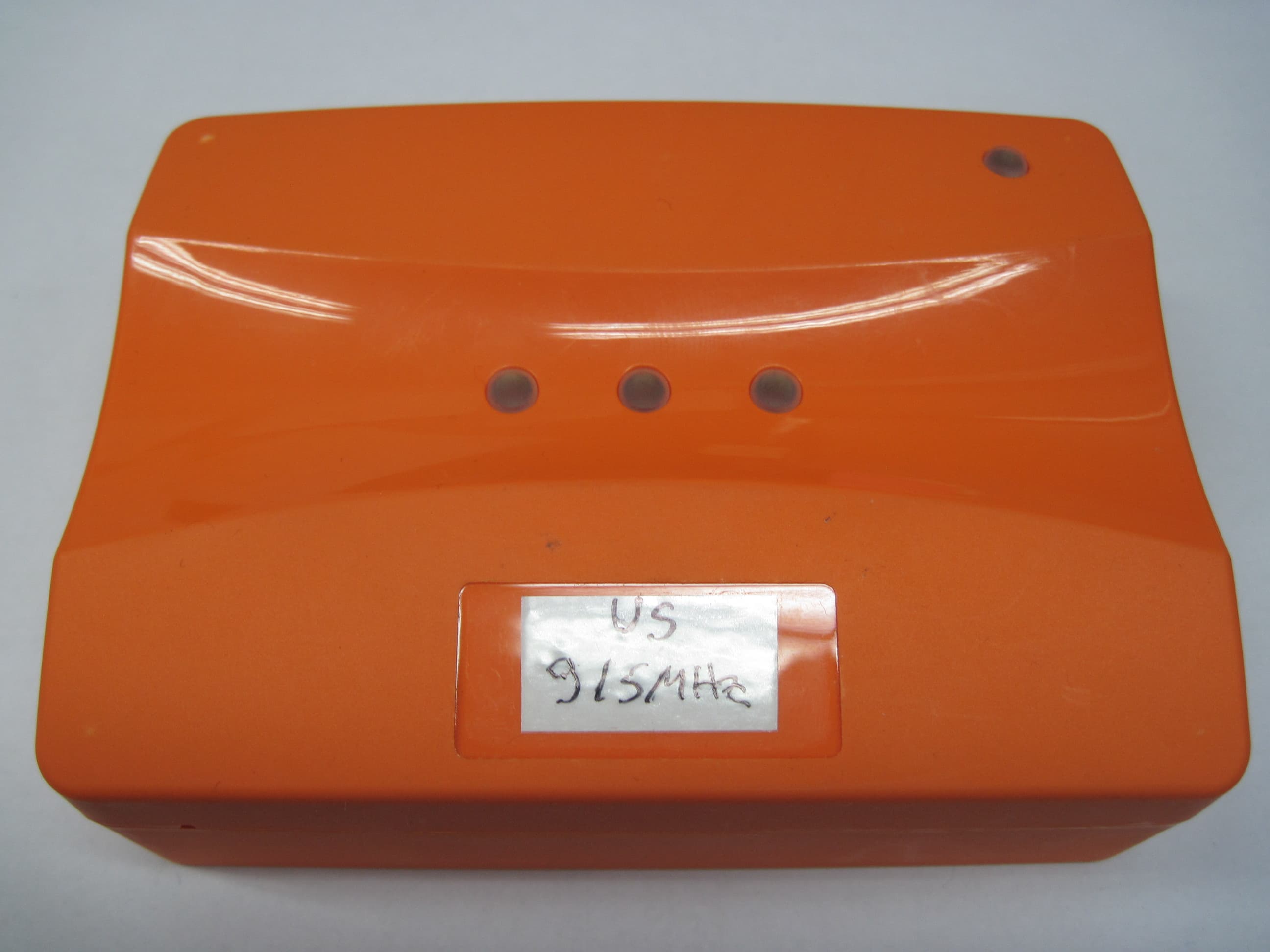
Click to zoom
Application Details
- Equipment Class
- DXX - Part 15 Low Power Communication Device Transmitter
- Date of Grant
- Jun 08, 2014
- Application Purpose
- Original Equipment
- Date of Application
- Jun 08, 2014
- Equipment Note
- Wireless Power Sensor PAN-42
- Frequency Range
- 915.00000000 - 915.00000000
- Company
- Panoramic Power ltd.
- Country
- Israel
Documents & Files
Document Text
Text extracted from the exhibit documents filed with the FCC. Open a document above to read the original.
Users Manual
Panoramic Power ® System PAN-42 User Guide PAN-42 User Guide 2 Copyright Notice Copyright © 2014 Panoramic Power Ltd. All rights reserved. PANORAMIC POWER® is a registered trademark of Panoramic Power Ltd. All other trademarks are the property of their respective owners FCC Compliance Statement This device has been tested and found to comply with the limits for a Class B digital device, pursuant to Part 15 of the FCC Rules. These limits are designed to provide reasonable protection against harmful interference in residential installations. This equipment generates uses and can radiate radio frequency energy and, if not installed and used in accordance with the instructions, may cause harmful interference to radio and television reception. However, there is no guarantee that interference will not occur in a particular installation. If this device does cause such interference, which can be verified by turning the device off and on, the user is encouraged to eliminate the interference by one or more of the following measures: Re-orient or re-locate the receiving antenna. Increase the distance between the device and the receiver. Connect the device to an outlet on a circuit different from the one that supplies power to the receiver. Consult the dealer or an experienced radio/TV technician. WARNING! Changes or modifications to this unit not expressly approved by the party responsible for compliance could void the user’s authority to operate the equipment. PAN-42 User Guide 3 FCC Declaration of Conformity Trade Name: Panoramic Power Product Name: Wireless Power Sensor Product Model Number: PAN-42-US This device complies with Part 15 of the FCC Rules. Operation is subject to the following two conditions: (1) This device may not cause harmful interference, and (2) this device must accept any interference received, including interference that may cause undesired operation. Responsible Party Name: Panoramic Power Inc. Address: 44 W. 28th Street, 8th Floor, New York, NY, 10001 Telephone: +1-646-794-4240 Manufacturer Name: Panoramic Power Ltd. Address: 20 Atir Yeda St., Kfar Saba 44643, Israel Telephone: +972-9-7667600 Date: _June 2 2014__ Signature: _________________________________________ Quality Assurance Manager of Manufacturer Printed Name: ____Moran Pekin___________ PAN-42 User Guide 4 Contents Overview ................................................................................................................ 5 Workflow ................................................................................................................ 5 Safety Precautions ................................................................................................. 5 Mechanical Installation ......................................................................................... 6 Electrical Connections........................................................................................... 8 Mapping the Site ................................................................................................... 9 Installing the Sensor .............................................................................................. 9 Registering the Installed Sensor ........................................................................ 10 Monitoring Sensor Activity ............................................................................... 10 Uninstalling a Sensor .......................................................................................... 11 Sensor Specifications ........................................................................................... 11 Certified CTs ........................................................................................................ 12 Support ................................................................................................................. 13 PAN-42 User Guide 5 Overview The PAN-42 wireless power sensor provides high-accuracy real-time power and power quality measurements for mains power monitoring, sub-metering and metering of large loads. Designed for demanding electrical applications, supporting industry accuracy standards, PAN-42 enables the metering of power, voltage, current, power factor and power quality measurement data. Information is sent wirelessly, through Panoramic Power’s Bridge unit, to Panoramic Power’s advanced cloud-based analytics platform. The data is then used to provide customers with actionable analytics and real-time dashboards and alerts. Workflow Sensor installation consists of the following steps: 1. Map the circuits. See Panoramic Power Deployment Tool User Guide. 2. Physically attach the sensor and the CTs to the wires. 3. Monitors the proper functioning of the sensor. See Panoramic Power Deployment Tool User Guide. Safety Precautions Read the instructions in this manual before installing, and take note of the following precautions: Ensure that all incoming AC power and other power sources are turned OFF before performing any work or connecting the PAN-42. Failure to do so may result in serious or even fatal injury and/or equipment damage. PAN-42 User Guide 6 Under no circumstances should PAN-42 be connected to a power source if it is damaged. To prevent potential fire or shock hazard, do not expose PAN-42 to rain or moisture. Ensure that the external current transformers are shorted (by using the recommended shorting switches) before disconnecting PAN42 from its current inputs. The sensor and CTs should be installed and removed only by a qualified electrician. Read this manual thoroughly before connecting the device to the current-carrying circuits. During operation of the device, hazardous voltages are present on input terminals. Failure to observe precautions can result in serious or even fatal injury, or damage to equipment. Mechanical Installation There are several mounting options for PAN-42: On a 35-mm DIN rail (see the drawing below) By using screws, using the slots on the back…
Text truncated - open the document above for the full version.
ID Label/Location Info
Revision Panoramic Power - PAN-LB-42-US-B DescriptionDate RevAPAN 42- US back label12/05/14 Back of Bridge PN PAN-LB-42-US-BPAN42 US Back label 49 x 29, R=1.2 DescriptionSize [wxh in mm] Includes company logo part number: "PAN-42-US" part number barcode serial number (generated in production) serial number barcode (generated in production) FCC text: "FCC ID: Z9M-PAN-4-2" ETL logo 7-digit control number below it Part name - Power sensor Design instructions: Part name Font: Helvetica Neue LT Std 55 Roman 10 px; kerning: 0 Part barcode size: 29.5x 3.5 mm Serial number font: Helvetica Neue LT Std 55 Roman 12 px; kerning: 0 Serial number barcode size: 17x3.5 mm Control number font: Helevetica Neue LT STD 47 Light Condensed 8 px, Kerning: 12 ‘FCC’ text font: Helevetica Neue LT STD 47 Light Condensed 8 px, Kerning: 12 ‘POWER SENSOR’- font: Helvetica Neue LT Std 45 Light 8 px; kerning: 80, Capitals Text & Barcode color: PANTONE 426 C Background color: Silver Please maintain the spaces and sizes as in this design. Panoramic logo pantone: PANTONE 426 C - Black PANTONE 368 C - Green Actual size: PAN-42-US 80689 POWER SENSOR FCC ID: Z9M-PAN-4-2 PAN-42-US 80689 POWER SENSOR FCC ID: Z9M-PAN-4-2 PAN-42-US 80689 POWER SENSOR FCC ID: Z9M-PAN-4-2 PAN-42-US 80689 POWER SENSOR FCC ID: Z9M-PAN-4-2 Revision Panoramic Power - PAN-LB-42-US-B DescriptionDate RevAPAN 42- US back label Instructions12/05/14 Design instructions: POWER SENSOR 1 2 4 5 1 2 1 3 6 Space from top-h:1.26 mm Space from logo bottom to part name-h:1.378 mm Space from left edge-w:4.052 mm Space from text to barcode-h:0.601 Space from barcode to text-h:1.009 Space from barcode to bottom-h:1.155 Panoramic logo size: 34.1x7.824 [wxh] Shape size: 4x29 [wxh] space from left and right shape edges: w:0.958 space from top and bottom shape edges: h:2.473 Space from left edge-w:1.332 mm 3 78 ETL logo size: 7.939x8.363 [wxh] 2 Space from Number to black shape:1.974 Space from ETL to bottom: h:3.881 Space from ETL logo to black shape:2.179 10 9
Operational Description
Panoramic Power USA - 44 W 28 th St. 8 th Fl, New York, NY 10001/Phone:+1-646794-4240;E-Mail: [email protected] Panoramic Power Israel-20 Atir Yeda St., Kfar Saba 44643, Israel/Phone: +972-9-766-7600; E-Mail: [email protected] Panoramic Power’s Wireless Power Sensor PAN-42 www.panpwr.com Key Features Single or 3 phase metering Accurate measurement of active and reactive power Real time monitoring of current, voltage, power and power quality Integrated within the Panoramic Power cloud based energy management platform Fast and easy installation The PAN-42 wireless power sensor provides high accuracy real time power measurements and advanced power quality measurements for main power monitoring, submetering and for the metering of large devices. Designed for demanding electrical applications, supporting industry accuracy standards, Pan42 enables the metering of power, voltage, current, power factor and power quality measurement data. Information is sent wirelessly, through Panoramic’s Bridge unit, to Panoramic’s advanced cloud-based analytics platform. The data is then used to provide customers with actionable analytics and real-time dashboards and alerts. PAN-42 complements the Panoramic Power sensor family (PAN-10, PAN-12 and PAN-14) that is used for more granular monitoring of individual circuits and devices. Together, they deliver a comprehensive range of metering and monitoring tools to reduce energy costs and maximize energy efficiency. Specifications PAN-42 4-wire Wye, 3-wire Delta, single-phase 3-wire, single-phase 2-wire, or dual-phase 3-wire Voltage: [120V / 208V], [240V / 416V], or [277V / 480V] Frequency: 48-62 Hz CT current input: standard 0-5 A rms Current measurement range: Depending on CT ratio Minimum current (at device input) ≤ 0.05 A rms (1%of full scale) Outputs Active Energy (kWh) – accumulated True RMS Voltage/Current – per phase Active/Reactive Power – per phase Power Factor – per phase Total Harmonic Distortion (%) – per phase (Voltage and Current) Neutral current Frequency Accuracy (for Voltage, Current and Active Energy) According to IEC687 (Class 0.5)* According to ANSI C12.20 (Class 0.5)* *Assuming CT of class 0.2 or better Pulse output 2 optically isolated outputs for active and reactive energy (kWh) Transmission frequency 434 MHz (EU) 915 MHz (US) Transmission power (ERP)* 0 dBm (Max) Transmission interval 10 seconds *Safety and EMC certificates USA & Canada Safety: UL-61010-1, CSA-C22.2 (ETL listed) EMC/Radio: FCC Part 15 subpart B, C Europe Safety: EN-61010-1 (CE) EMC: EN-ETSI 301489-3, Radio: EN-ETSI 300220-1 Dimensions Weight Mounting Options 110.3 × 81 × 37.2 mm 4.34 × 3.19 × 1.46 inch 200 g Wall mount or DIN top hat rail EN50022 - 35x7.5 Flammability rating of external enclosure UL94 V-0 Operating temperature 0 – 50° C 32- 122 F Storage temperature -20 – 65° C -4-149 F Display 3 LEDs for phase indications and additional LED for on line status indication. *Pending certification testing ** Product is not available yet. Content is not final and may be changed or modified in the future
Test Report
Test Report E137961.01 Panoramic Power Ltd. Page 1 of 41 ITL FCCMASVE 1.25 26 March 2003 DATE: 26 March 2014 I.T.L. (PRODUCT TESTING) LTD. FCC Radio Test Report for Panoramic Power Ltd. Equipment under test: Wireless Power Sensor PAN-42-US Written by: ____________________________ R. Pinchuck, Documentation Approved by: _____________________________ A. Sharabi, Test Engineer Approved by: _____________________________ I. Raz, EMC Laboratory Manager This report must not be reproduced, except in full, without the written permission of I.T.L. (Product Testing) Ltd. This report relates only to items tested. Test Report E137961.01 Panoramic Power Ltd. Page 2 of 41 ITL FCCMASVE 1.25 26 March 2003 Measurement/Technical Report for Panoramic Power Ltd. Equipment under test: Wireless Power Sensor PAN-42-US FCC ID: Z9M-PAN-4-2 This report concerns: Original Grant: x Class I change: Class II change: Equipment Type: Digital Transmission System Limits used: 47CFR15 Section 15.249 Measurement procedure used is KDB 558074 D01 09 April 2013 and ANSI C63.4-2003. Application for Certification Applicant for this device: prepared by: (different from "prepared by") R. Pinchuck Adi Shamir ITL (Product Testing) Ltd. Panoramic Power Ltd. Kfar Bin Nun 20 Atir Yeda St. D.N. Shimshon 99780 Kfar Saba, 44643 Israel Israel Tel: +972-8-918-6117 Tel: 972-9-766-7600 Fax: +972-8-915-3101 Fax: 972-9-766-7610 Email: [email protected] Email: [email protected] Test Report E137961.01 Panoramic Power Ltd. Page 3 of 41 ITL FCCMASVE 1.25 26 March 2003 TABLE OF CONTENTS 1. GENERAL INFORMATION ------------------------------------------------------------------------------- 4 1.1 Administrative Information ................................................................................. 4 1.2 List of Accreditations ......................................................................................... 5 1.3 Product Description ........................................................................................... 6 1.4 Test Methodology .............................................................................................. 6 1.5 Test Facility ....................................................................................................... 6 1.6 Measurement Uncertainty ................................................................................. 6 2. SYSTEM TEST CONFIGURATION --------------------------------------------------------------------- 7 2.1 Justification ........................................................................................................ 7 2.2 Special Accessories .......................................................................................... 7 2.3 Equipment Modifications ................................................................................... 7 2.4 Configuration of Tested System ........................................................................ 7 3. CONDUCTED AND RADIATED MEASUREMENTS TEST SETUP PHOTOS -------------- 8 4. CONDUCTED EMISSION FROM AC MAINS -------------------------------------------------------11 4.1 Test Specification ............................................................................................ 11 4.2 Test Procedure ................................................................................................ 11 4.3 Measured Data ................................................................................................ 11 4.4 Test Instrumentation Used, Conducted Measurement ................................... 15 5. FIELD STRENGTH OF FUNDAMENTAL ------------------------------------------------------------16 5.1 Test Specification ............................................................................................ 16 5.2 Test Procedure ................................................................................................ 16 5.3 Test Results..................................................................................................... 16 5.4 Test Instrumentation Used, Field Strength of Fundamental ........................... 20 6. SPURIOUS RADIATED EMISSION 9 KHZ - 30 MHZ ---------------------------------------------21 6.1 Test Specification ............................................................................................ 21 6.2 Test Procedure ................................................................................................ 21 6.3 Test results ...................................................................................................... 21 6.4 Test Instrumentation Used, Radiated Measurements 9 kHz – 30 MHz .......... 22 6.5 Field Strength Calculation ............................................................................... 22 7. SPURIOUS RADIATED EMISSION 30 MHZ- 10 GHZ --------------------------------------------23 7.1 Test Specification ............................................................................................ 23 7.2 Test Procedure ................................................................................................ 23 7.3 Test Results..................................................................................................... 23 7.4 Test Instrumentation Used, Radiated Measurements 30 MHz – 10 GHz ....... 26 7.5 Field Strength Calculation ............................................................................... 26 8. BAND EDGE ATTENUATION --------------------------------------------------------------------------27 8.1 Test Specification ............................................................................................ 27 8.2 Test Procedure ................................................................................................ 27 8.3 Test Results..................................................................................................... 27 8.4 Test Instrumentation Used, Band Edge Attenuation ....................................... 30 9. AVERAGE FACTOR CALCULATION ---------------------------…
Text truncated - open the document above for the full version.
Test Setup Photos
Figure 1. Radiated Emission Test
Contact Information
Applicant
Yael Alali(Hardware Team Leader)
Test Firm
Israel Testing LaboratoriesIIan Cohen
Technical Specifications
| # | Rule Parts | Frequency Range | Power Output |
|---|---|---|---|
| 1 | 15C | 915 MHz - 915 MHz | - |
Other Applications from Panoramic Power ltd.
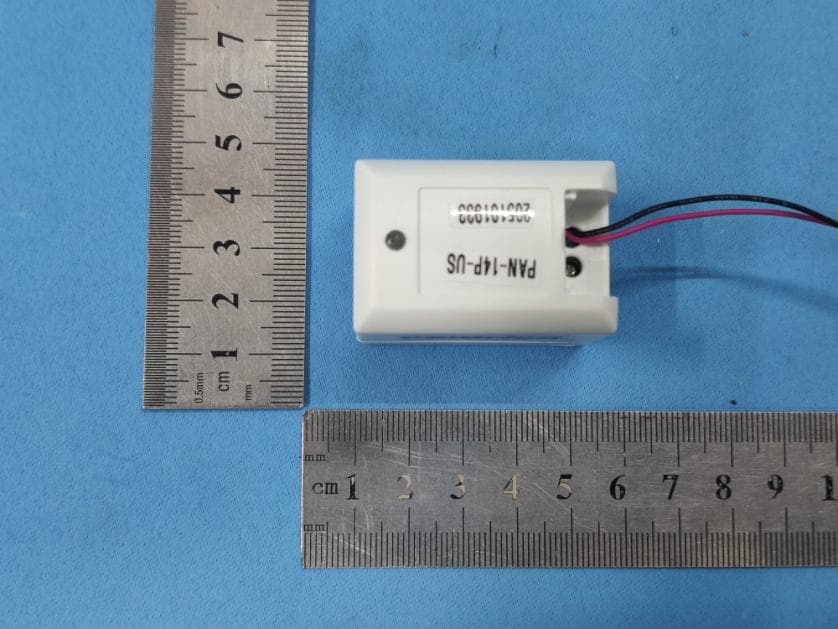
Z9M-PAN14P
Feb 09, 2021Wireless High Current Sensor with Power Measurement Ability
Equipment Class
DXX - Part 15 Low Power Communication Device Transmitter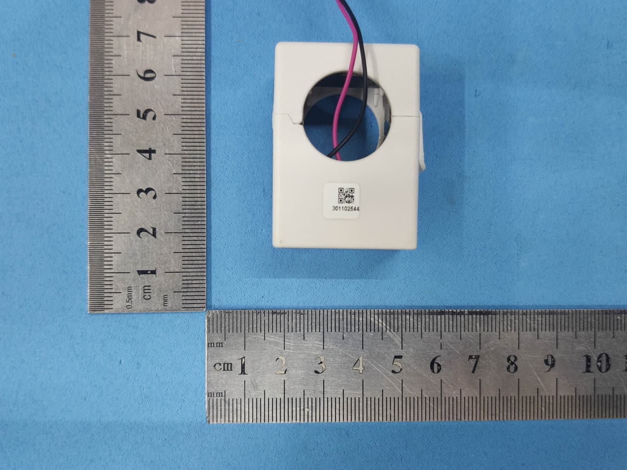
Z9M-PAN12P
Jan 06, 2021200A Wireless Current Sensor with Power Measurement Ability
Equipment Class
DXX - Part 15 Low Power Communication Device Transmitter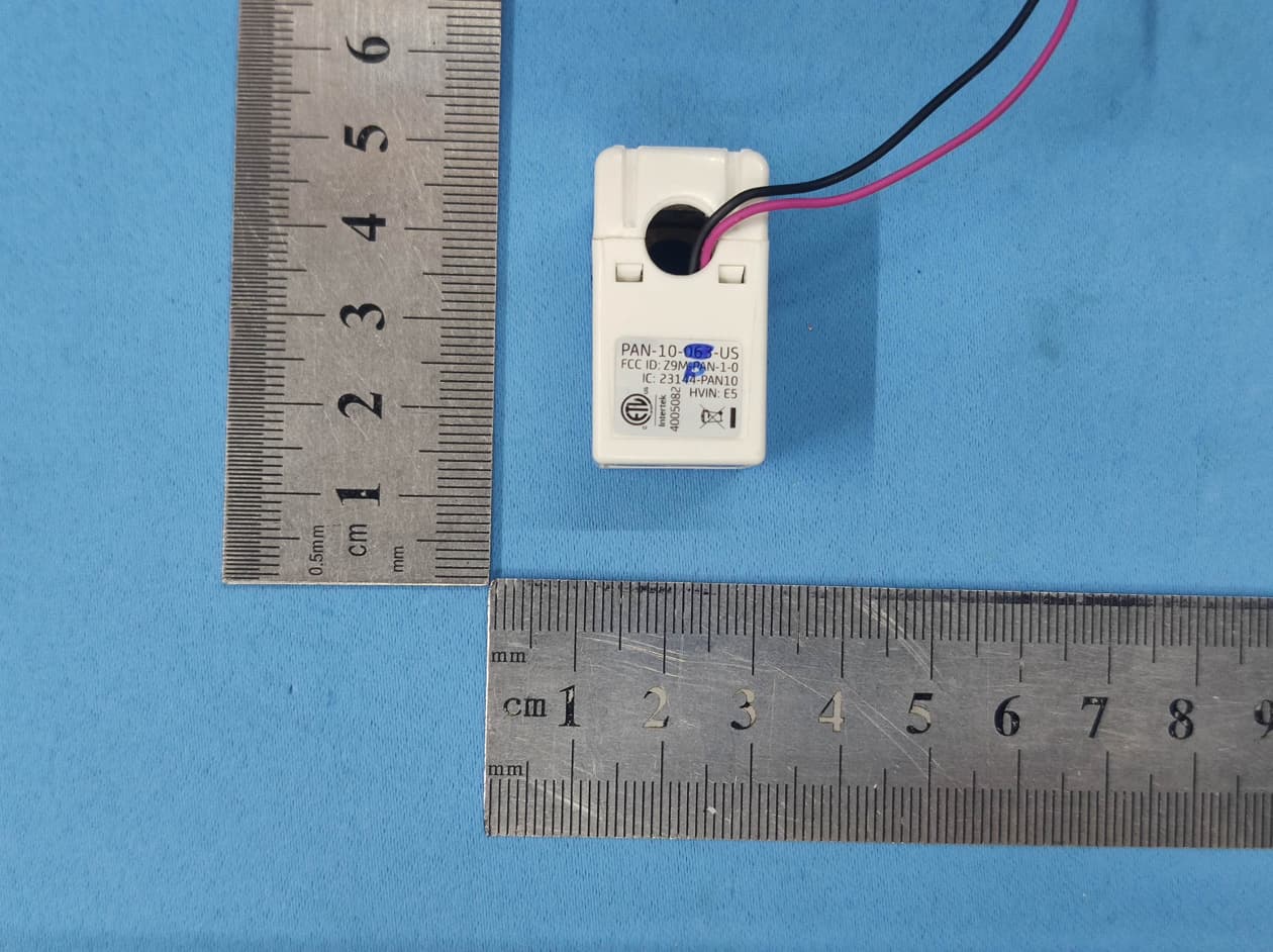
Z9M-PAN10P
Jan 05, 202163A Wireless Current Sensor with Power Measurement Ability
Equipment Class
DXX - Part 15 Low Power Communication Device Transmitter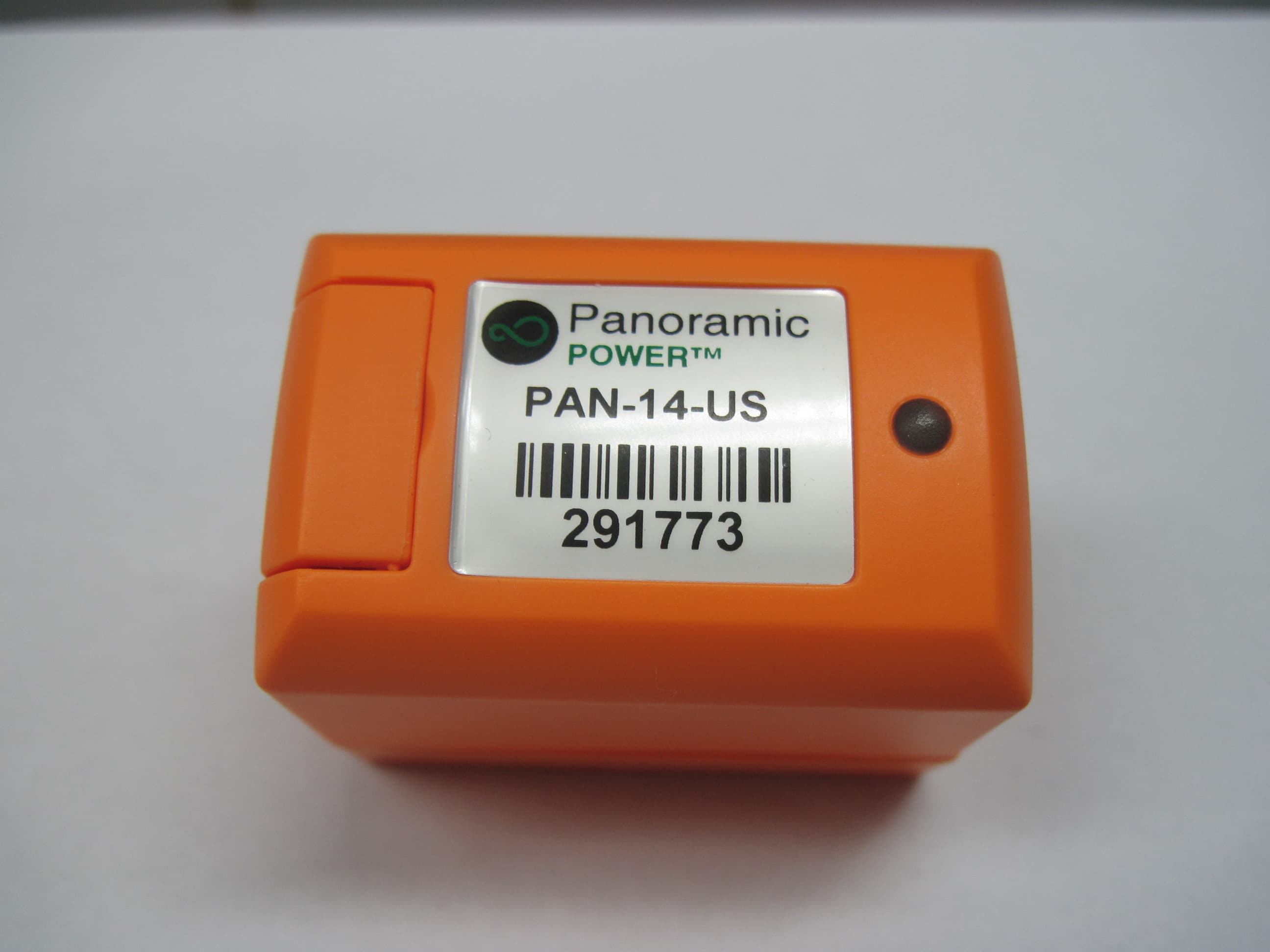
Z9M-PAN-1-4
May 26, 2014High Current Wireless Sensor PAN-14-US
Equipment Class
DXX - Part 15 Low Power Communication Device Transmitter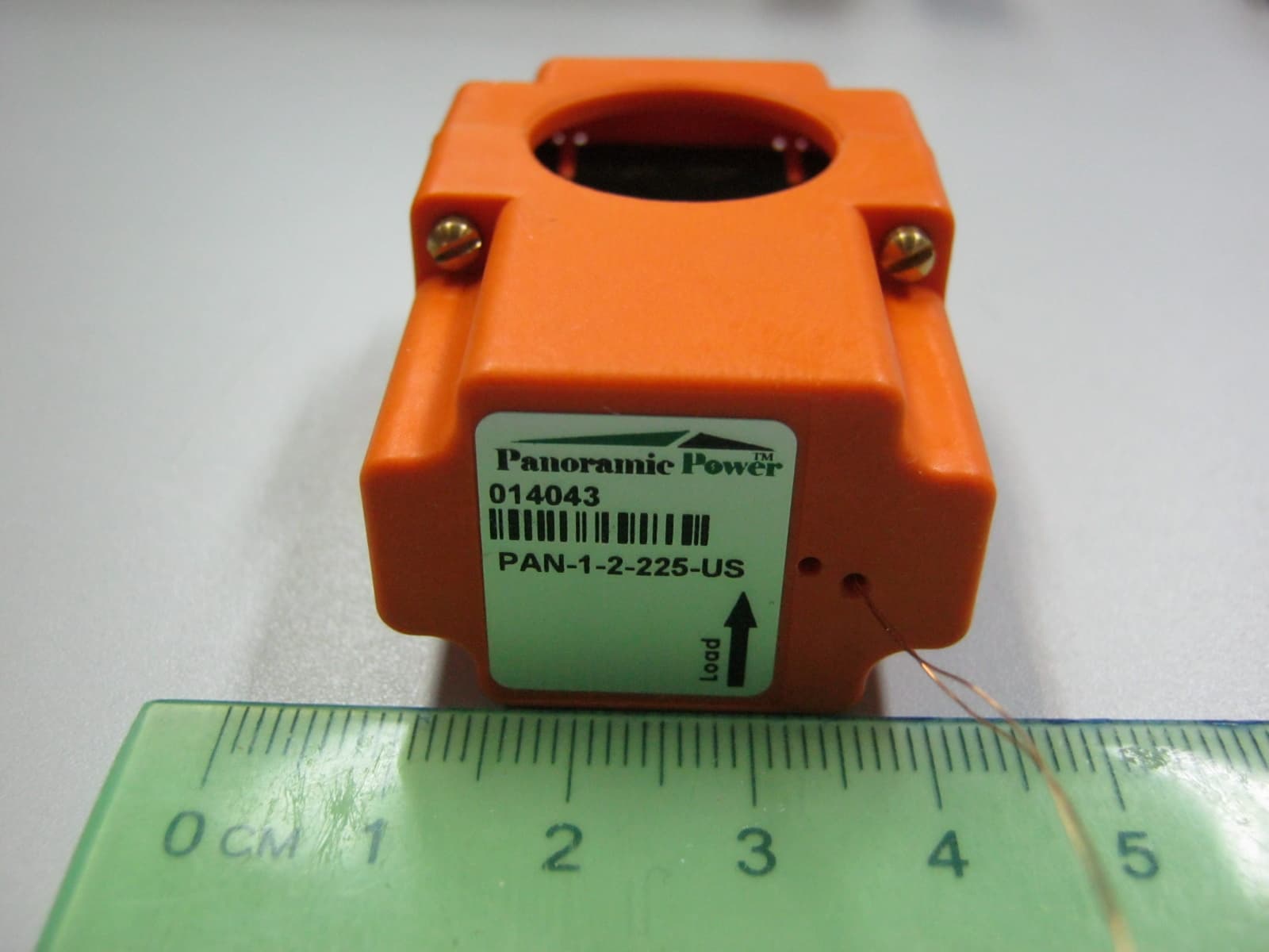
Z9M-PAN-1-2
Jul 31, 2012WIRELESS CURRENT SENSOR
Equipment Class
DXX - Part 15 Low Power Communication Device Transmitter