ZBNC16RInduction Cooker
Fruto Industrial International Ltd.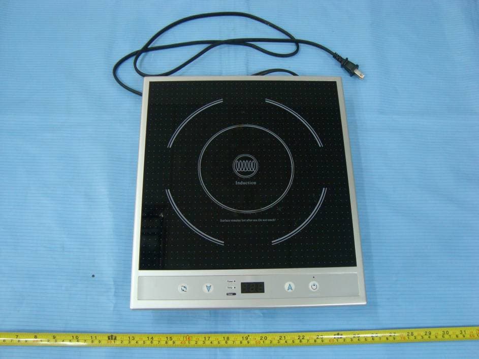
Click to zoom
Application Details
- Equipment Class
- 8CC - Part 18 Consumer Device
- Date of Grant
- Mar 06, 2011
- Application Purpose
- Original Equipment
- Date of Application
- Mar 06, 2011
- Equipment Note
- Induction Cooker
- Frequency Range
- 0.02000000 - 0.04000000
- Country
- China
Documents & Files
Document Text
Text extracted from the exhibit documents filed with the FCC. Open a document above to read the original.
Users Manual
I IMPORTANT SAFEGUARDS When using electrical appliances, basic safety precautions should always be followed including the following: 1. Read all instructions 2. Do not touch hot surfaces. Use handles or knobs. 3. To protect against electrical shock do not immerse cord, plugs, or (state specific part or parts in question) in water or other liquid. 4. Close supervision is necessary when any appliance is used by or near children. 5. Unplug from outlet when not in use and before cleaning. Allow to cool before putting on or taking off parts. 6. Do not operate any appliance with a damaged cord or plug or after the appliance malfunctions or has been damaged in any manner. Return appliance to the nearest authorized service facility for examination, repair, or adjustment. 7. The use of accessory attachments not recommended by the appliance manufacturer may cause injuries. 8. Do not use outdoors, household use only. 9. Do not let cord hang over edge of table or counter, or touch hot surfaces. 10. Do not place on or near a hot gas or electric burner, or in a heated oven. 11. Always attach plug to appliance first, then plug cord into the wall outlet( For the detached power cord).To disconnect, turn any control to off, then remove plug from wall outlet. 12. Do not use appliance for other than intended use. 13. Do not immerse in water. 15. A short power-supply cord(or detached power supply cord) is to be provided to reduce the risk resulting from becoming entangled in or tripping over a longer cord. 16. Longer detached power supply cord or extension cords are available and may be used if care is exercised in their use. 17. If a longer detached power supply cord or extension cords power-supply cord is used, a) The marked electrical rating of the extension cord should be at least as great as the electrical rating of the appliance, and b) The cord should be arranged so that it will not drape over the countertop or tabletop where it can be pulled on by children or tripped over unintentionally. 18. Do Not Cook on Broken Cook-Top – If cook-top should break, cleaning solutions and spillovers may penetrate the broken cook-top and create a risk of electric shock. 19. Clean Cook-Top with Caution – If a wet sponge or cloth is used to wipe spills on a hot cooking area, be careful to avoid steam burn, some cleaners can produce noxious fumes if applied to a hot surface. 20.Do not heat the pot empty or overheat it. 21. Do not place metallic objects such as knives, forks, spoons, lids, cans and aluminum foils on the top plate. 22. Allow sufficient space around the cooking area. 23. Never use the unit on low-heat-resistant materials (carpet, vinyl). 24. Do not place a sheet of paper between the pot or the pan and the unit. The paper may get burnt. 25. Be aware that the unit surface will remain hot for a short period of time. 26. Items with a magnetic field, such as: radios, televisions, automatic-banking cards and cassette tapes, can affect the unit. 27.This appliance has a polarized plug (one blade is wider than the other). To reduce the risk of electric shock, this plug is intended to fit into a polarized outlet only one way. If the plug does not fit fully into the outlet, reverse the plug. If it still does not fit, contact a qualified electrician. Do not attempt modify the plug in any way. SAVE THESE INSTRUCTIONS. SPECIFICATION:II z Item: C16R z Power Rate: 1600W z Voltage:120V z Operating Frequency:20kHz~40kHz HOW TO USEIII 1. Before turning on the power, make sure the cookware is on the ceramic plate with ingredients inside. Page 1 of 3 2. To turn the power on, press the ON/OFF button once. The power light will turn a steady red and heating will begin 3. To select the proper heat setting, press the REDUCE or INCREASE until the correct heat setting is achieved.(defaults=5, from 1 to 10 level) 4. To select temperature setting, press the” function” button once(defaults=270) ,the temperature light °F will turn a steady red ,and press the REDUCE or INCREASE until the correct temperature setting is achieved. (The temperature is between 150 to °F450°F,150,180,210,240,270,300,330, 360,390,420,450°F) 5. To select automatic timer setting, press the” function” button twice (defaults =0min),the timer light will turn a steady red ,and press the REDUCE or INCREASE until the correct timer setting is achieved. You will be able to select the operating time in increasing 5 minutes, and reducing 1 minute. (The timer is between 0 to 150 mins). After 5 seconds to finish setting the Timer Function, the unit will return to Power or Temp Function. If you want to check or change the setting timer, please press the Function key, and change to Timer function to adjust. 6. After cooking is completed, press the ON/OFF button again to turn off the unit. 7. After the cooking time reach 150 mins, the LED will show “EE” and sound, and then the unit will enter the standby mode. Press the ON/OFF button to restart the unit. Notice: If using the unit in TEMP or HEAT Function, not setting the TIMER Function, but when the unit is used 150 mins, the LED display shows EE code and sound. The unit will stop automatically. If using the unit in TEMP or HEAT Function 10 mins, and then set the TIMER, the max Timer is 140 mins. During timer operation, you can change the duration at any time with the arrow keys. NOTE: The power will completely shut off with 9 second if either (a) the wrong type of cookware is applied or (b) no cookware is placed on the unit. USABLE AND NONIV-USABLE UTENSILS: z Compatible Pans: Steel or cast iron, enameled iron, stainless steel, flat-bottom pan/pots with diameter of 12 to26 cm. z Non- compatible Pans: Heat-resistant glass, ceramic container, copper, aluminum pan/pots. Rounded-bottom pan/pots with the base measuring less than 12cm. HOW TO CLEAN:V z Clean after each use. Disconnect plug and wait until the unit has cooled down. z If the pots/pans are used without being cleaned, as this may result in discoloration or stains. z Do no…
Text truncated - open the document above for the full version.
External Photos
EXHIBIT B - EUT EXTERNAL PHOTOGRAPHS EUT – Top View EUT – Bottom View
Internal Photos
EXHIBIT C - EUT INTERNAL PHOTOGRAPHS EUT – Cover off View EUT – Control Board Top View EUT – Control Board Bottom View EUT – Mainboard Top View EUT – Main Board Bottom View EUT – Induction Coil Front View EUT – Induction Coil Rear View
Schematics
12 LIN 12 LOUT 12 C5 0.33uF/1200VDC IBGT2 H20R1202 R1 47R R46 30K R18 15.5K 1 2 N L2300uH 1 2 L C16 8uF/400DC F1 T15AH 250VAC 2 1 FAN +5V BZ 4K +5V C9 10uF D1 1N4007 D2 1N4007 R14 10K R8 12K C12 101 C15 104 R6 2K R7 2K +18V C14 104 R24 3K +5V R22 1K PPG RJ1 16mOhm C10 104 R25 1K R12 820K R11 30K C6 221 C20 2J102J 2V >3V C17 104 AC=270V4.0V VDD PB3 PB3 PPG BZDR/TCC/PA7 OSCI/PB4 OSCO/PB3 RESET/PC5 CO2/PB7/ADC7 VR1 500R R16 39K R9 3.3K C2 221 1 2 3 4 5 6 7 8 9 CON9 C8 104 R17 22K +5V T R-NTC MDJ-104-3950-5 1 2 3 HITE AC 1 AC 2 + 3 - 4 BG1 D25SB80 Q3 S8050 Q4 S8550 Q5 S8050 C7 104 R13 820K D3 4148 D8 1N4007 R4 820K R15 820K R27 820K Q2 SS8050 C13 103J C28 10uF/450V C27 223 D9 BYV26C C25 1uF/50V D7 UF4007 C23 100uF/25V Vin 1 G N D 2 Vout 3 U2 78L05 C24 470uF/10V C11 104 +5V C26 100uF/25V 1 1 2 2 3 3 4 4 5 5 6 6 7 7 8 8 U3 VIPer-12A Z1 +18V C18 100uF/25V VDD 1 32 4 L4 143×82 D6 RF107 R5 120R R26 22R C3N/PA5 1 C3P/PB2 2 PPWM/PA6 3 BZDR/TCC/PA7 4 VSS 5 OSCI/PB4 6 OSCO/PB3 7 RESET/PC5 8 CO2/PB7/ADC7 9 CO3/PB6/ADC5 10 PC3/ADC3/CAIN 13 PC2/ADC2 14 PC1/ADC1 15 PC0/ADC0 16 VDD 17 PB0/C4P/VREF 18 PA1/CO1 19 PB1/C1P 20 PA2/C1N 21 PA0/C4N 22 PB5/CO4/ADC5 11 PC4/INT/ADC4 10 C2N/PA3 23 C2P/PA4 24 U1 R19 20K +5V PB5/CO4/ADC5 PB5/CO4/ADC5 CO2/PB7/ADC7 RESET/PC5 OSCO/PB3 OSCI/PB4 BZDR/TCC/PA7 R20 9.2K R23 2K R21 240R C19 2J102J C1 4.7uF/275V Q1 S8050 R2 68K C21 104 IBGT1 H20R1202 R34 30K R48 47R J5 39K P0BG101 P0BG102 P0BG103 P0BG104 P0BZ01 P0BZ02 P0C101 P0C102 P0C201 P0C202 P0C501 P0C502 P0C601 P0C602 P0C701 P0C702 P0C801 P0C802 P0C901 P0C902 P0C1001 P0C1002 P0C1101 P0C1102 P0C1201 P0C1202 P0C1301 P0C1302 P0C1401 P0C1402 P0C1501 P0C1502 P0C1601 P0C1602 P0C1701 P0C1702 P0C1801 P0C1802 P0C1901 P0C1902 P0C2001 P0C2002 P0C2101 P0C2102 P0C2301 P0C2302 P0C2401 P0C2402 P0C2501 P0C2502 P0C2601 P0C2602 P0C2701 P0C2702 P0C2801 P0C2802 P0CON901 P0CON902 P0CON903 P0CON904 P0CON905 P0CON906 P0CON907 P0CON908 P0CON909 P0D101 P0D102 P0D201 P0D202 P0D301 P0D302 P0D601 P0D602 P0D701 P0D702 P0D801 P0D802 P0D901 P0D902 P0F101 P0F102 P0HITE01 P0HITE02 P0HITE03 P0IBGT10C P0IBGT10E P0IBGT10G P0IBGT20C P0IBGT20E P0IBGT20G P0J501 P0J502 P0L201 P0L202 P0L401 P0L402 P0L403 P0L404 P0LIN01 P0LIN02 P0LOUT01 P0LOUT02 P0N01 P0N02 P0L01 P0L02 P0FAN01 P0FAN02 P0Q101 P0Q102 P0Q103 P0Q201 P0Q202 P0Q203 P0Q301 P0Q302 P0Q303 P0Q401 P0Q402 P0Q403 P0Q501 P0Q502 P0Q503 P0R0NTC01 P0R0NTC02 P0R101 P0R102 P0R201 P0R202 P0R401 P0R402 P0R501 P0R502 P0R601 P0R602 P0R701 P0R702 P0R801 P0R802 P0R901 P0R902 P0R1101 P0R1102 P0R1201 P0R1202 P0R1301 P0R1302 P0R1401 P0R1402 P0R1501 P0R1502 P0R1601 P0R1602 P0R1701 P0R1702 P0R1801 P0R1802 P0R1901 P0R1902 P0R2001 P0R2002 P0R2101 P0R2102 P0R2201 P0R2202 P0R2301 P0R2302 P0R2401 P0R2402 P0R2501 P0R2502 P0R2601 P0R2602 P0R2701 P0R2702 P0R3401 P0R3402 P0R4601 P0R4602 P0R4801 P0R4802 P0RJ101 P0RJ102 P0U101 P0U102 P0U103 P0U104 P0U105 P0U106 P0U107 P0U108 P0U109 P0U1010 P0U1011 P0U1013 P0U1014 P0U1015 P0U1016 P0U1017 P0U1018 P0U1019 P0U1020 P0U1021 P0U1022 P0U1023 P0U1024 P0U201 P0U202 P0U203 P0U301 P0U302 P0U303 P0U304 P0U305 P0U306 P0U307 P0U308 P0VR101 P0VR102 P0VR103 P0Z101 P0Z102 P0BZ02 P0C1101 P0C1701 P0C2401 P0CON907 P0HITE01 P0HITE02 P0R0NTC02 P0U1017 P0U203 P0C1501 P0C1801 P0D302 P0Q302 P0R502 P0R602 P0R702 P0CON909 P0U104 N0BZDR/TCC/PA7 N0BZDR/TCC/PA7 P0CON904 N0CO2/PB7/ADC7 N0CO2/PB7/ADC7 P0C202 P0C602 P0C701 P0C802 P0C902 P0C1002 P0C1102 P0C1402 P0C1502 P0C1602 P0C1702 P0C1802 P0C2102 P0C2302 P0C2402 P0C2602 P0C2802 P0CON901 P0D901 P0IBGT10E P0IBGT20E P0L403 P0Q103 P0Q203 P0Q403 P0Q503 P0R902 P0R1101 P0R1402 P0R1702 P0R1801 P0R2402 P0R3402 P0R4602 P0RJ101 P0U105 P0U1020 P0U202 P0BG101 P0C101 P0D101 P0F102 P0R201 P0BG103 P0L201 P0BG104 P0C1001 P0R2501 P0RJ102 P0BZ01 P0R2102 P0C201 P0C1202 P0R401 P0R1802 P0U1023 P0C501 P0C1601 P0L202 P0LIN01 P0LIN02 P0R402 P0C502 P0IBGT10C P0IBGT20C P0LOUT01 P0LOUT02 P0R2702 P0C601 P0C2002 P0R1102 P0R1202 P0U101 P0C702 P0R2002 P0U1016 P0C801 P0R1701 P0R0NTC01 P0U1014 P0C901 P0R1401 P0R1502 P0U1010 P0C1201 P0J502 P0R1602 P0C1301 P0R1902 P0U1021 P0VR102 P0VR103 P0C1302 P0R1901 P0R2001 P0U1019 P0C1401 P0HITE03 P0R2401 P0U1015 P0C1901 P0Q101 P0R2302 P0C1902 P0R2301 P0C2001 P0R1201 P0R1302 P0R1501 P0C2501 P0D702 P0U304 P0Z102 P0C2502 P0C2702 P0D902 P0L401 P0U301 P0U302 P0C2601 P0D602 P0U201 P0C2701 P0U303 P0Z101 P0C2801 P0R2601 P0U305 P0U306 P0U307 P0U308 P0D102 P0D202 P0D801 P0R1301 P0D301 P0Q303 P0Q402 P0R102 P0R4802 P0D601 P0L404 P0D802 P0R2602 P0IBGT10G P0R3401 P0R4801 P0IBGT20G P0R101 P0R4601 P0J501 P0U1024 P0Q102 P0Q501 P0R701 P0Q201 P0R2201 P0Q301 P0Q401 P0Q502 P0R601 P0R801 P0R901 P0U1022 P0R802 P0R1601 P0R2701 P0R2101 P0U102 P0R2202 P0U1010 P0R2502 P0VR101 P0U103 P0U106 P0U107 P0U108 P0U109 P0U1011 P0U1013 P0U1018 P0FAN01 P0Q202 P0CON908 N0OSCI/PB4 N0OSCI/PB4 P0CON906 N0OSCO/PB3 N0OSCO/PB3 P0CON902 N0PB3 N0PB3 P0CON903 N0PB5/CO4/ADC5 N0PB5/CO4/ADC5 N0PPG P0CON905 N0RESET/PC5 N0RESET/PC5 P0C2101 P0C2301 P0D701 P0FAN02 P0L402 P0R501 P0BZ02 P0C1101 P0C1701 P0C2401 P0CON907 P0HITE01 P0HITE02 P0R0NTC02 P0U1017 P0U203 P0C1501 P0C1801 P0D302 P0Q302 P0R502 P0R602 P0R702 N0BZDR/TCC/PA7 P0CON909 P0U104 N0CO2/PB7/ADC7 P0CON904 P0C202 P0C602 P0C701 P0C802 P0C902 P0C1002 P0C1102 P0C1402 P0C1502 P0C1602 P0C1702 P0C1802 P0C2102 P0C2302 P0C2402 P0C2602 P0C2802 P0CON901 P0D901 P0IBGT10E P0IBGT20E P0L403 P0Q103 P0Q203 P0Q403 P0Q503 P0R902 P0R1101 P0R1402 P0R1702 P0R1801 P0R2402 P0R3402 P0R4602 P0RJ101 P0U105 P0U1020 P0U202 P0BG101 P0C101 P0D101 P0F102 P0R201 P0BG103 P0L201 P0BG104 P0C1001 P0R2501 P0RJ102 P0BZ01 P0R2102 P0C201 P0C1202 P0R401 P0R1802 P0U1023 P0C501 P0C1601 P0L202 P0LIN01 P0LIN02 P0R402 P0C502 P0IBGT10C P0IBGT20C P0LOUT01 P0LOUT02 P0R2702 P0C601 P0C2002 P0R1102 P0R1202 P0U101 P0C702 P0R2002 P0U1016 P0C801 P0R1701 P0R0NTC01 P0U1014 P0C901 P0R1401 P0R1502 P0U1010 P0C1201 P0J502 P0R1602 P0C1301 P0R1902 P0U1021 P0VR102 P0VR103 P0C1302 P0R1901 P0R2001 P0U1019 P0C1401 P0HITE03 P0R2401 P0U1015 P0C1901 P0Q101 P0R2302 P0C1902 P0R2301 P0C2001 P0R1201 P0R1302 P0R1501 P0C2501 P0D702 P0U3…
Text truncated - open the document above for the full version.
Test Report
Note: This test report is prepared for the customer shown above and for the device described herein. It may not be duplicated or used in part without prior written consent from Bay Area Compliance Laboratories Corp. This report must not be used by the customer to claim product certification, approval, or endorsement by NVLAP*, NIST, or any agency of the Federal Government. * This report contains data that are not covered by the NVLAP accreditation and are marked with an asterisk “★” (Rev.2) FCC PART 18 MEASUREMENT AND TEST REPORT For Fruto Industrial International Ltd Unit 1921, 19/F, China Shine Plaza, No. 3-15 Lin He Road west, Tian He, Guangzhou, China FCC ID: ZBNC16R Report Type: Original Report Product Type: Induction Cooker Test Engineer: Grace Xi Report Number: RSZ10122366 Report Date: 2011-03-04 Reviewed By: Lisa Zhu EMC Engineer Prepared By: Bay Area Compliance Laboratories Corp. (Shenzhen) 6/F, the 3rd Phase of WanLi Industrial Building, ShiHua Road, FuTian Free Trade Zone Shenzhen, Guangdong,China Tel: +86-755-33320018 Fax: +86-755-33320008 Fruto Industrial International Ltd FCC ID: ZBNC16R Report No.: RSZ10122366 Page 2 of 13 FCC Part 18 Test Report TABLE OF CONTENTS GENERAL INFORMATION.......................................................................................................................................3 PRODUCT DESCRIPTION FOR EQUIPMENT UNDER TEST (EUT) .....................................................................................3 OBJECTIVE...................................................................................................................................................................3 RELATED SUBMITTAL(S)/GRANT(S).............................................................................................................................3 TEST METHODOLOGY..................................................................................................................................................3 TEST FACILITY.............................................................................................................................................................3 SYSTEM TEST CONFIGURATION ..........................................................................................................................5 JUSTIFICATION.............................................................................................................................................................5 EUT EXERCISE SOFTWARE..........................................................................................................................................5 SPECIAL ACCESSORIES.................................................................................................................................................5 EQUIPMENT MODIFICATIONS.......................................................................................................................................5 EXTERNAL I/O CABLE..................................................................................................................................................5 CONFIGURATION OF TEST SETUP.................................................................................................................................5 BLOCK DIAGRAM OF TEST SETUP................................................................................................................................6 FCC §18.307 - CONDUCTED EMISSIONS ...............................................................................................................7 MEASUREMENT UNCERTAINTY....................................................................................................................................7 EUT SETUP..................................................................................................................................................................7 EMI TEST RECEIVER SETUP.........................................................................................................................................8 TEST EQUIPMENT LIST AND DETAILS...........................................................................................................................8 TEST PROCEDURE........................................................................................................................................................8 TEST RESULTS SUMMARY............................................................................................................................................8 TEST DATA..................................................................................................................................................................8 FCC §18.305 - FIELD STRENGTH ..........................................................................................................................11 MEASUREMENT UNCERTAINTY..................................................................................................................................11 EUT SETUP................................................................................................................................................................11 EMI TEST RECEIVER SETUP AND SPECTRUM ANALYZER SETUP................................................................................12 TEST EQUIPMENT LIST AND DETAILS.........................................................................................................................12 TEST PROCEDURE......................................................................................................................................................12 CORRECTED AMPLITUDE & MARGIN CALCULATION.................................................................................................12 TEST RESULTS SUMMARY..........................................................................................................................................13 TEST DATA AND P…
Text truncated - open the document above for the full version.
Test Setup Photos
EXHIBIT D - TEST SETUP PHOTOGRAPHS Conduction Emissions - Front View Conduction Emissions - Side View Radiated Emissions - Front View Radiated Emissions - Rear View
Contact Information
Applicant
April Chan(Manager)
Test Firm
Bay Area Compliance Laboratory Corp. (Shenzhen)John Chan
Technical Specifications
| # | Rule Parts | Frequency Range | Power Output |
|---|---|---|---|
| 1 | 18 | 0.02 MHz - 0.04 MHz | - |
Other Applications from Fruto Industrial International Ltd.
ZBNTI3B
Aug 17, 2015INDUCTION COOKTOP
Equipment Class
8CC - Part 18 Consumer Device
ZBNC18-13
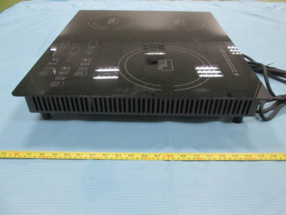
Jun 28, 2015Induction Cooker
Equipment Class
8CC - Part 18 Consumer Device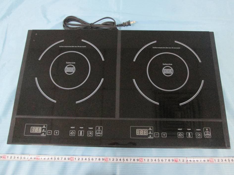
ZBNS2F1
May 07, 2015INDUCTION COOKER
Equipment Class
8CC - Part 18 Consumer Device
ZBNF-IH-01SS
Nov 26, 2014Induction cooker
Equipment Class
8CC - Part 18 Consumer Device
ZBN-C15Y3
Jan 26, 2014Induction cooker
Equipment Class
8CC - Part 18 Consumer Device