ZKZ-33505Receiver GR-12S HoTT
Graupner GmbH & Co. KG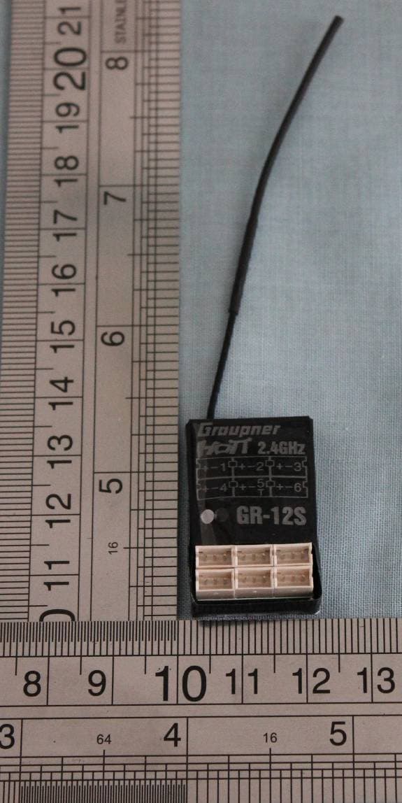
Click to zoom
Application Details
- Equipment Class
- DSS - Part 15 Spread Spectrum Transmitter
- Date of Grant
- Jun 13, 2011
- Application Purpose
- Original Equipment
- Date of Application
- Jun 13, 2011
- Equipment Note
- Receiver GR-12S HoTT
- Frequency Range
- 2404.00000000 - 2474.00000000
- Company
- Graupner GmbH & Co. KG
- Country
- Germany
Documents & Files
Document Text
Text extracted from the exhibit documents filed with the FCC. Open a document above to read the original.
Users Manual
Graupner GmbH & Co. KGHenriettenstraße 94 – 96D-73230 Kirchheim/TeckGermanywww.graupner.deÄnderungen sowie Liefermöglichkeiten vorbehalten. Lieferung durch den Fachhandel. Bezugsquellen werden nachgewiesen. Für Druckfehler kann keine Haftung übernommen werden.Speci fi cations and availability subject to change. Supplied through specialist model shops only. We will gladly inform you of your nearest supplier. We accept no liability for printing errors.Sous réserve de modi fi cations et de possibilité de livraison. Livraison uniquement au travers de maga- sins spécialisés en modélisme. Nous pourrons vous communiquer l’adresse de votre revendeur le plus proche. Nous ne sommes pas responsables d’éventuelles erreurs d’impression.Con riserva di variazione delle speci fi che e disponibilità del prodotto. Fornitura attraverso rivenditori specializzati.Saremmo lieti di potervi indicare il punto vendita più vicino a voi. Si declina qualsiasi res-ponsabilità per errori di stampa.HoTT 1.0 / March 2011 - EN V1.2 GRAUPNER GmbH & Co. KG – Postfach 1242 – 73230 Kirchheim/Teck – www.graupner.de Manual 33505 Receiver GR-12S HoTT 33506 Receiver GR-12 HoTT CONTENTS:1. General Note ............................................................................................................ .. 01 2. Functions .................................................................................................................... 01 2.1. Binding ................................................................................................................. ........ 01 2.2. Binding Multiple Receivers .......................................................................................... 012.3. Fail-Safe Function ........................................................................................................ 02 3. Receiver .................................................................................................................. .... 02 3.1. Connections ............................................................................................................. .... 02 3.2. Low Voltage Warning ................................................................................................... 023.3. Temperature Warning .................................................................................................. 034. Firmware Update ........................................................................................................ 03 4.1. Receiver ................................................................................................................ ...... 03 4.2. Update Procedure ........................................................................................................ 03 5. Declaration of Conformity ......................................................................................... 05 6. Warranty .................................................................................................................. ... 07 Manual V1.2 Revision: March 2011 Thank you for purchasing the Graupner HoTT 2.4 System Please read through this entire manual before you attempt the installation and usage of your Graupner HoTT 2.4 System!These operating instructions are part of this product. They contains important notes to the operation and handling. Please take this into consideration when you pass on the product to third parties. Neglect of the operating instructions and the safety instructions lead to expiring the warranty. Graupner constantly work on the advancement of all remote control systems; changes of the scope of deli-very in form, technology and equipment we must reserve ourselves therefore. Please have understanding for the fact that from data and illustrations of this operating instructions no requirements can be derived.Please keep these instructions for further reference!1. GENERAL NOTEWhen switching on or adjusting the radio control system it is essential to keep the transmitter aerial at least 15 cm away from the receiver aerials at all times. If the transmitter aerial is too close to the receiver aerials, the receiver will be overloaded, causing the green LED starts fl ashing. The transmitter responds by emitting a beep once every second; the red LED also goes out. The radio control system is now in Fail-Safe mode.If this should occur, simply increase the distance between the aerials until the audible warning signal ceases, and the red LED on the transmitter lights up again; at the same time the green LED on the receiver should glow constantly.2. FUNCTIONS 2.1. BindingWhen you wish to use the Graupner HoTT 2.4 GHz receiver with a particular transmitter, the fi rst step must always be to “bind” the unit to “its” Graupner HoTT 2.4 GHz RF module (transmitter). This “binding” procedure only needs to be carried out once for each combination of receiver and RF module. The units supplied in the set are already bound to each other at the factory, i.e. the binding procedure described in the following section only needs to be carried out when you wish to use an additional receiver. However, it can also be repeated at any time if required, e.g. after changing transmitters. When binding is required, this is the procedure:• Switch the transmitter and receiver on. • Locate the BIND / RANGE button on the back of the transmitter, and hold it pressed in while you press and hold the SET button on the receiver. Both LEDs on the back of the transmitter now glow constantly, and the green LED on the receiver fl ashes. • If the green fl ashing LED on the receiver begins to glow permanently within about ten seconds, this indicates that the binding process is complete. You can now release both buttons, and your transmitter / receiver combination is ready for use. • However, if the green LED on the receiver continues to fl ash for longer than ten seconds, then the binding process has failed. If this should occur, repeat the whole procedure. 2.2. Binding“ multiple receivers in one modelIf …
Text truncated - open the document above for the full version.
Cover Letter(s)
SCS-F18: Project and Product Certification Representative Authorization Letter Page 1 of 2 Rev 2.0 2206 Ringwood Avenue San Jose, CA 95131 Tel: 408-526-1188 Fax: 408-526-1088 Email: [email protected] Project and Product Certification Representative Authorization Letter Revision History Reason for Amendment (current / obsolete) From To Approved Date Initial Release (current) Revised wording (current) SCS-F18: Project and Product Certification Representative Authorization Letter Page 2 of 2 Rev 2.0 Graupner GmbH & Co. KG May 23, 2011 To: SIEMIC, INC. 2206 Ringwood Avenue, San Jose, CA 95131 USA Dear Sir/Madam, Re: Project and Product Certification Representative Authorization Letter We, Graupner GmbH & Co. KG hereby authorize SIEMIC, INC. to act as a Certification Body for certifying for the following project(s): (Product description, Receiver GR-12S HoTT model name, GR-12S ) We affirm that between SIEMIC and Graupner GmbH & Co. KG , any difference in understanding, including test plan, measurement methods, applicable standards and relevant procedures and processes have been resolved prior to commencement of testing activities. Sincerely, Client’s signature: Client’s name / title: Head of Development Dept. Contact information / address: Henriettenstr. 94-96 D-73230 Kirchheim/Teck GERMANY
Cover Letter(s)
Graupner GmbH & Co. KG Date: September 2, 2011 Federal Communications Commission 7435 Oakland Mills Road Columbia MD 21046 Subject:Request for Confidentiality FCC ID:ZKZ-33505 To Whom It May Concern: Pursuant to the provisions of Sections 0.457 and 0.459 of the Commission’s rules (47 CFR §§ 0.457, 0.459), we are requesting the Commission to withhold the following attachments as confidential document from public disclosure indefinitely. - Block Diagram - Schematics - Operational Description Above mentioned document contains detailed system and equipment description are considered as proprietary information in operation of the equipment. The public disclosure of above documents might be harmful to our company and would give competitor an unfair advantage in the market. It is our understanding that all measurement test reports, FCC ID label format and correspondent during certification review process cannot be granted as confidential documents and those information will be available for public review once the grant of equipment authorization is issued. We decide to apply for confidentiality now, after getting FCC ID certificates because we were not aware of this issue when applying for Certificate." Signature Best Regards Name : Ralf Helbing Title: Head of Development Dept. Company Name: Graupner GmbH & Co. KG Address: Henriettenstr. 94-96 D-73230 Kirchheim/Teck Germany. Email: [email protected] Telephone: :+49/7021/722-185
External Photos
External Photographs EUT –Top View EUT –Rear View
ID Label/Location Info
FCC Label Sample FCC ID: ZKZ-33505 Product: Receiver GR-12S HoTT Model: GR-12S
ID Label/Location Info
FCC ID Label Location FCC ID Label Location
Internal Photos
Internal Photographs EUT – Uncovered View EUT –PCB View
RF Exposure Info
1 Radio Frequency Exposure Graupner GmbH & Co. KG FCC ID: ZKZ-33505 Product Description: Receiver GR-12S HoTT Model No.: GR-12S Prepared for: Graupner GmbH & Co. KG Henriettenstr. 94-96 D-73230 Kirchheim Teck,Germany Prepared by: Shenzhen Laker Testing Technology Co.,Ltd 15C,Block 1,Sunshine Huayi Building,Nanhai West Road, Nanshan, Shenzhen, China Tel: 86-755-27617110 Fax: 86-755-27617110 Report No.: LK11ER-00104E Issue Date: May 26, 2011 Te s t D a t e : May 05~20, 2011 Te s t b y : Reviewed By: Owen Li Edmund Zou 2 LIMIT Systems operating under the provisions of this section shall be operated in a manner that ensures that the public is not exposed to radio frequency energy levels in excess of the Commission's guidelines. See FCC part 15.247(i)and §1.1307(b)(1) of this chapter. EUT Specification EUT Receiver GR-12S HoTT Type of Modulation: FHSS Frequency Band: 2404 MHz ~ 2474 MHz Number of Channels: 70 Channel Bandwidth: 1 MHz Device category Portable (<20cm separation) Mobile (>20cm separation) Others __________________________ Exposure classification Occupational/Controlled exposure (S = 5mW/cm 2 ) General Population/Uncontrolled exposure (S=1mW/cm 2 ) Antenna diversity Single antenna Multiple antennas Tx diversity Rx diversity Tx/Rx diversity Max. output power -2.02dBm (0.628mW) Antenna gain (Max) 1.5 dBi Evaluation applied MPE Evaluation SAR Evaluation Note: 1. The maximum output power is -2.02dBm (0.628mW)) at 2404MHz (with 1.5 numeric antenna gain.) 2. For mobile or fixed location transmitters, no SAR consideration applied. The minimum separation generally be used is at least 20 cm, even if the calculations indicate that the MPE distance would be lesser. TEST RESULT No non-compliance noted. 3 Calculation Given d GP E ×× = 30 & 3770 2 E S= Where E = Field Strength in Volts / meter P = Power in Watts G=Numeric antenna gain d=Distance in meters S=Power Density in milliwatts / square centimeter Combining equations and re-arranging the terms to express the distance as a function of the remaining variables yields: 2 3770 30 d GP S ×× = Changing to units of mW and cm, using: P (mW) = P (W) / 1000 and d (cm) =100 * d (m) Yields 2 )100/(3770 )1000/(30 d GP S × ×× = = 2 0796.0 d GP × × Equation 1 Where d = distance in cm P = Power in mW G = Numeric antenna gain S = Power Density in mW / cm 2 Maximum Permissible Exposure EUT Output Power=0.628mW Numeric antenna gain=1.5 Substituting the MPE safe distance using d=20 cm into Equation 1 : Yields S=0.000199 × P × G Where P = Power in mW G = Numeric antenna gain S = Power Density in mW / cm2 The power density S = 0.000199 × 0.628 × 1.5=0.00019 mW / cm2 (For mobile or fixed location transmitters, the maximum power density is 1.0 mW / cm 2 even if the calculation indicates that the power density would be larger.) Evaluation reslut : PA S S
Test Report
Test Report of FCC Part 15 C for FCC Certificate On Behalf of Graupner GmbH & Co. KG FCC ID: ZKZ-33505 Product Description: Receiver GR-12S HoTT Model No.: GR-12S Prepared for: Graupner GmbH & Co. KG Henriettenstr. 94-96 D-73230 Kirchheim Teck,Germany Prepared by: Shenzhen Laker Testing Technology Co.,Ltd 15C,Block 1,Sunshine Huayi Building,Nanhai West Road, Nanshan, Shenzhen, China Tel: 86-755-27617110 Fax: 86-755-27617110 Report No.: LK11ER-00104E Issue Date: May 26, 2011 Test Date: May 05~20, 2011 Test by: Reviewed By: Owen Li Edmund Zou Report No.: LK11ER-00104E Page 2 of 46 FCC ID: ZKZ-33505 TABLE OF CONTENTS 1. GENERAL INFORMATION....................................................................................................................................4 1.1 PRODUCT DESCRIPTION FOR EQUIPMENT UNDER TEST (EUT).........................................................................4 1.2 RELATED SUBMITTAL(S) / GRANT (S)...................................................................................................................4 1.3 TEST METHODOLOGY...........................................................................................................................................4 1.4 TEST FACILITY......................................................................................................................................................5 2. SYSTEM TEST CONFIGURATION......................................................................................................................6 2.1 EUT CONFIGURATION..........................................................................................................................................6 2.2 EUT EXERCISE.....................................................................................................................................................6 2.3 GENERAL TEST PROCEDURES.............................................................................................................................6 2.4 LIST OF MEASURING EQUIPMENTS USED............................................................................................................7 3. SUMMARY OF TEST RESULTS...........................................................................................................................9 4. TEST OF HOPPING CHANNEL BANDWIDTH................................................................................................10 4.1 APPLICABLE STANDARD.....................................................................................................................................10 4.2 EUT SETUP........................................................................................................................................................10 4.3 TEST EQUIPMENT LIST AND DETAILS.................................................................................................................10 4.4 TEST PROCEDURE..............................................................................................................................................10 4.5 TEST RESULT......................................................................................................................................................10 5. TEST OF HOPPING CHANNEL SEPARATION...............................................................................................14 5.1 APPLICABLE STANDARD.....................................................................................................................................14 5.2 EUT SETUP........................................................................................................................................................14 5.3 TEST EQUIPMENT LIST AND DETAILS.................................................................................................................14 5.4 TEST PROCEDURE..............................................................................................................................................14 5.5 TEST RESULT......................................................................................................................................................14 6. TEST OF NUMBER OF HOPPING FREQUENCY...........................................................................................18 6.1 APPLICABLE STANDARD.....................................................................................................................................18 6.2 EUT SETUP........................................................................................................................................................18 6.3 TEST EQUIPMENT LIST AND DETAILS.................................................................................................................18 6.4 TEST PROCEDURE..............................................................................................................................................18 6.5 TEST RESULT......................................................................................................................................................18 7. TEST OF DWELL TIME OF EACH FREQUENCY...........................................................................................20 7.1 APPLICABLE STANDARD.....................................................................................................................................20 7.2 EUT SETUP........................................................................................................................................................20 7.3 TEST EQUIPMENT LIST AND DETAILS.................................................................................................................20 7.4 TEST PROCEDURE..............................................................................................................................................20 7.5 TEST RESULT................................................................…
Text truncated - open the document above for the full version.
Test Setup Photos
TEST SETUP PHOTOGRAPHS Radiated Emission
Contact Information
Applicant
Ralf Helbing(manager)
Test Firm
CENTRE TESTING INTERNATIONAL CORPORATIONChristy Chen
Technical Specifications
| # | Rule Parts | Frequency Range | Power Output |
|---|---|---|---|
| 1 | 15C | 2.40 GHz - 2.47 GHz | 628.00 µW |
Other Applications from Graupner GmbH & Co. KG

ZKZ-MC-16
Jan 27, 2013ComputerSystem Graupner/SJ HoTT
Equipment Class
DSS - Part 15 Spread Spectrum Transmitter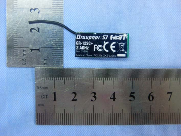
ZKZ-33566
Dec 10, 2012Slow Flyer Receiver Graupner/SJ HoTT
Equipment Class
DSS - Part 15 Spread Spectrum Transmitter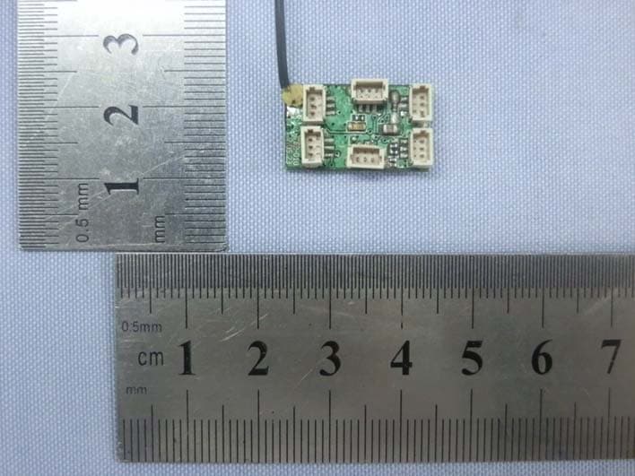
ZKZ-33565
Dec 10, 2012Slow Flyer Receiver Graupner/SJ HoTT
Equipment Class
DSS - Part 15 Spread Spectrum Transmitter
ZKZ-MC-20
Aug 26, 2012COMPUTER SYSTEM GRAUPNER/SJ HOTT
Equipment Class
DSS - Part 15 Spread Spectrum Transmitter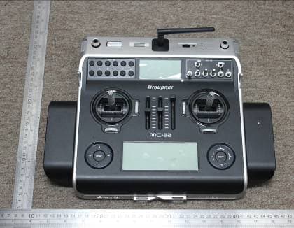
ZKZ-MC-32
Dec 21, 2011ComputerSystem Graupner HoTT
Equipment Class
DSS - Part 15 Spread Spectrum Transmitter