ZKZ-33566Slow Flyer Receiver Graupner/SJ HoTT
Graupner GmbH & Co. KG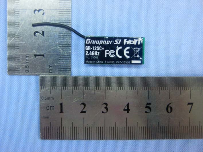
Click to zoom
Application Details
- Equipment Class
- DSS - Part 15 Spread Spectrum Transmitter
- Date of Grant
- Dec 10, 2012
- Application Purpose
- Original Equipment
- Date of Application
- Dec 10, 2012
- Equipment Note
- Slow Flyer Receiver Graupner/SJ HoTT
- Frequency Range
- 2404.00000000 - 2479.00000000
- Company
- Graupner GmbH & Co. KG
- Country
- Germany
Documents & Files
Document Text
Text extracted from the exhibit documents filed with the FCC. Open a document above to read the original.
Users Manual
Graupner GmbH & Co. KG Henriettenstraße 94 – 96 D-73230 Kirchheim/Teck Germany www.graupner.de Änderungen sowie Liefermöglichkeiten vorbehalten. Lieferung durch den Fachhandel. Bezugsquellen werden nachgewiesen. Für Druckfehler kann keine Haftung übernommen werden. Specifi cations and availability subject to change. Supplied through specialist model shops only. We will gladly inform you of your nearest supplier. We accept no liability for printing errors. Sous réserve de modifi cations et de possibilité de livraison. Livraison uniquement au travers de maga- sins spécialisés en modélisme. Nous pourrons vous communiquer l’adresse de votre revendeur le plus proche. Nous ne sommes pas responsables d’éventuelles erreurs d’impression. Con riserva di variazione delle specifi che e disponibilità del prodotto. Fornitura attraverso rivenditori specializzati.Saremmo lieti di potervi indicare il punto vendita più vicino a voi. Si declina qualsiasi res- ponsabilità per errori di stampa. EN V1.0 PN.QH-01 Manual 33565Receiver GR-12SH+ HoTT 33566Receiver GR-12SC+ HoTT CONTENTS: 1. General Note .............................................................................................................. 01 2. Functions .................................................................................................................... 01 2.1. Binding ......................................................................................................................... 01 2.2. Fail-Safe Function ........................................................................................................ 02 3. Receiver ...................................................................................................................... 02 3.1. Connections ................................................................................................................. 02 3.2. Programming ............................................................................................................... 02 3.3. Operation ..................................................................................................................... 02 4. Firmware Update ........................................................................................................ 04 4.1. Update Procedure ........................................................................................................ 05 5. Declaration of Conformity ......................................................................................... 07 6. Warranty ..................................................................................................................... 09 GRAUPNER GmbH & Co. KG – Postfach 1242 – 73230 Kirchheim/Teck – www.graupner.de Manual V1.0 Revision: August 2012 Thank you for purchasing the receiver GR-12SH+ or SC+ for the Graupner HoTT 2.4 System. Please read through this entire manual before you attempt the installation and usage of your Graupner HoTT 2.4 System! These operating instructions are part of this product. They contains important notes to the operation and hand- ling. Please take this into consideration when you pass on the product to third parties. Neglect of the operating instructions and the safety instructions lead to expiring the warranty. Graupner constantly work on the advancement of all remote control systems; changes of the scope of de- livery in form, technology and equipment we must reserve ourselves therefore. Please have understanding for the fact that from data and illustrations of this operating instructions no requirements can be derived. Please keep these instructions for further reference! Intended use The receiver is specifi cally designed for slow-fl y models whose components are fi tted with SH or ZH connec- tors. The maximum range is around 300 m, which is appropriate to this type of model. The receiver must not be used in any model which requires greater range, or whose servos draw a current which exceeds the maximum permissible for SH connectors (#33565 max. 0.5 A) or ZH connectors (#33566 max. 1 A). This product works with any Graupner HoTT 2.4 GHz transmitter, but with no others. If you do not own a Graupner HoTT 2.4 system, the receiver will not function. This product is not compatible with any other 2.4 GHz radio control system. It is not suitable for young people under fourteen years. If a young person below that age wishes to use it, he or she must be supervised by an adult. Before using the receiver for the fi rst time, please read and observe all the warnings and safety notes in these instructions and on the packaging. WARNINGS Do not connect servos to this receiver whose current drain exceeds the maximum permissible for• SH connectors (#33565 max. 0.5 A) or ZH connectors (#33566 max. 1 A). If channel 1 is used as an electronic speed controller, the continuous current of the motor connec-• ted to it must never exceed 2 A, otherwise the receiver could be ruined! If several independent models / receivers are operated close together - e.g. for glider towing - the receivers • must be kept a minimum of 50 cm apart, otherwise there is a danger of interaction between them. For the same reason the pilots on the ground should stand at least 5 m apart. 1. GENERAL NOTE When switching on or adjusting the radio control system it is essential to keep the transmitter aerial at least 15 cm away from the receiver aerials at all times. If the transmitter aerial is too close to the receiver aerials, the receiver will be overloaded, causing the red LED starts fl ashing. The transmitter responds by emitting a beep once every second; the red LED also goes out. The radio control system is now in Fail-Safe mode. If this should occur, simply increase the distance between the aerials until the audible warning signal ceases, and the red LED on the transmitter lights up again; at the same time the red LED on the receiver should go out. 2. FUNCTIONS 2.1. Binding When you wish to use the Graupner HoTT 2.4 GHz r…
Text truncated - open the document above for the full version.
Cover Letter(s)
FCC Confidentiality Request Number: CF303 Version: V05 Date: 21-05-2012 (Permanent or also called long term confidentiality is the normal method to keep certain docuements confidential, and may apply to schematics, block diagrams, operational description and bill of materials.) To: Federal Communications Commission Equipment Authorization Branch 7435 Oakland Mills Road Columbia, MD 21046 Pursuant to 47 CFR Section 0.459(a) & (b), we, (the applicant / grantee) Company name Graupner GmbH & Co. KG Address Henriettenstr. 94-96 D-73230 Kirchheim/Teck GERMANY City Kirchheim Country GERMANY request for this certification filing under: Grantee Code Product Number FCC ID:ZKZ-33566 to maintain permanent confidentiality for the following documents submitted within this application: (please cross what is applicable, or add other documents, provide the file name and description) Exhibit File Name Description Operational Description ZKZ-33566_CircuitDescription.pdf explaining the functioning of the block diagram Block Diagrams ZKZ-33566_Block Diagram.pdf showing the systematic building blocks of the EUT Schematics Diagrams ZKZ-33566_Schematic Diagram.pdf showing components, their values and interconnection Bill of Materials List of components used on the PCB’s of the EUT Above materials crossed contain secrets, proprietary and technical information, which would customarily be guarded from competitors under 47 CFR, section 0.457(d)(2). Disclosure or publication or any portion of this company confidential material to other parties could cause substantial competitive harm and provide unjustified benefits for competitors. We understand that pursuant to 47 CFR section 0.457(d)(1)(ii) disclosure of the applicant and all accompanying documentation will not be made before the date of the grant. The documents indicated as confidential above, are not publicly available elsewhere. Attestation: City and Country: Date: Name: (this must be a person) Function: Signature: (or official company stamp) SHEN ZHEN 2012-12-03 Ralf Helbing Head of Development Dept Graupner GmbH & Co. KG ZKZ-33566 FCC ID:
Cover Letter(s)
Graupner GmbH & Co. KG FCC Modular Approval Request Number:CF305 Version: V04 Date: 07-08-2012 To the FCC or FCC TCB handling this application Hereby we, Company name (grantee)Graupner GmbH & Co. KG AddresssHenriettenstr. 94-96 D-73230 Kirchheim/Teck GERMANY City / ZIP / State / CountryKirchheim GERMANY request modular approval for the certification of our equipment within this application, identified by: FCC ID:ZKZ-33566 The table below contains the justification for modular approval of this equipment: Requirement per 15.212 and KDB 996369 D01 Module Certification Guide v01r03Explanation from grantee (do not write yes / no, but explain why it complies / how it is achieved) 1. The modular transmitter must have its own RF shielding.YES: Module has metal shielding, so complies. 2. The modular transmitter must have buffered modulation/data inputs (if such inputs are provided) to ensure that the module will comply with Part 15 requirements under conditions of excessive data rates or over-modulation. YES: Module has buffered in and outputs, so complies 3. The modular transmitter must have its own power supply regulation.YES: Module has power stabilization, so complies. 4. The modular transmitter must comply with the antenna requirements of Section 15.203 and 15.204(c). The antenna must either be permanently attached or employ a “unique” antenna coupler (at all connections between the module and the antenna, including the cable).. YES: Has a fixed wire antenna, so complies 5. The modular transmitter must be tested in a stand-alone configuration, i.e., the module must not be inside another device during testing. This is intended to demonstrate that the module is capable of complying with Part 15 emission limits regardless of the device into which it is eventually installed. YES: Was tested stand alone, see setup. 6. The modular transmitter must be labeled with its own FCC ID number, and, if the FCC ID is not visible when the module is installed inside another device, then the outside of the device into which the module is installed must also display a label referring to the enclosed module. This exterior label can use wording such as the following: “Contains Transmitter Module FCC ID: XYZMODEL1” or “Contains FCC ID: XYZMODEL1.” Any similar wording that expresses the same meaning may be used. The Grantee may either provide such a label, an example of which must be included in the application for equipment authorization, or, must provide adequate instructions along with the module which explain this requirement. In the latter case, a copy of these instructions must be included in the application for equipment authorization. YES: Module is labeled with FCC ID: ZKZ-33566 User manual provides instructions how to label the host and integrate the module 7. The modular transmitter must comply with any specific rule or operating requirements applicable to the transmitter and the manufacturer must provide adequate instructions along with the module to explain any such requirements. A copy of these instructions must be included in the application for equipment authorization. For example, there are very strict operational and timing requirements that must be met before a transmitter is authorized for operation under Section 15.231. For instance, data transmission is prohibited, except for operation under Section 15.231(e), in which case there are separate field strength level and timing requirements. Compliance with these requirements must be assured. YES: Module integration explained in manual 8. The modular transmitter must comply with any applicable RF exposure requirements. For example, FCC Rules in Sections 2.1091, 2.1093 and specific Sections of Part 15, including 15.319(i), 15.407(f), 15.253(f) and 15.255(g), require that Unlicensed PCS, UNII and millimeter wave devices perform routine environmental evaluation for RF Exposure to demonstrate compliance. In addition, spread spectrum transmitters operating under Section 15.247 are required to address RF Exposure compliance in accordance with Section 15.247(b)(4). Modular transmitters approved under other Sections of Part 15, when necessary, may also need to address certain RF Exposure concerns, typically by providing specific installation and operating instructions for users, installers and other interested parties to ensure compliance. YES: Module is compliant for ̈mobile ̈ applications (with unmodified fixed antenna) at a minimum user distance of 20cm from the antenna. Further module RF exposure advise for integration is provided in the manual Attestation (by grantee) City and Country:Date:Name: (this must be a person) Function:Signature: (or official company stamp) SHEN ZHEN 2012-12-3 Ralf Helbing Head of Development Dept
Cover Letter(s)
FCC Authorization Letter Number: CF304 Version: V03 Date: 01-08-2011 We, (the approval holder) Company name Graupner GmbH & Co. KG Address Henriettenstr. 94-96 D-73230 Kirchheim/Teck GERMANY City Kirchheim Country GERMANY declare that the following representative (agent): Name (person) Tony Wu Company name Bontek Compliance Laboratory Co., Ltd. Address 1/F, Block East H-3,OCT Eastern Ind. Zone, Qiaocheng East Road, Nanshan, City Shenzhen,Guangdong Country China is hereby authorized to apply the following equipment for certification on our behalf: Product Description Slow Flyer Receiver Graupner/SJ HoTT Type or Model(s) GR-12SC+ Tradename or Brand(s) HoTT We also authorize Teleconformity (Mr. M. Koop, Manager Certification, Address: Rietven 31, 7534NH Enschede, the Netherlands) to apply and sign this application for certification, registration or filing on our behalf (as representative agent or certifier). Attestation: City and Country: Date: Name: (this must be a person) Function: Signature: (or official company stamp) SHEN ZHEN 2012-12-03 Graupner GmbH & Co. KG Head of Development Dept Graupner GmbH & Co. KG
External Photos
External Photographs EUT –Front View EUT – Rear View
ID Label/Location Info
FCC ID Label Sample
ID Label/Location Info
FCC ID Location FCC ID Location
Internal Photos
Internal Photographs EUT - PCB View Antenna base EUT -PCB View
RF Exposure Info
MPE Calculation (for Mobile Device) FCC ID: ZKZ-33566 Power density limit for mobile devices at 2.4 GHz: S ≤ 1 mW/cm 2 Remark: Average ≤ Peak, which means that calculating the power density applying Peak power is worst case. The worst case operation mode generating the highest power in each frequency range is taken for calculation. Frequency range: 2402-2479MHz Maximum measured conducted power (Peak): P conducted = 4.88 dBm Antenna Gain: G = 1 dBi User distance: 20cm Calculation: P radiated = P conducted + G linear = 4.88 dBm + 1 dBi = 5.88 dBm = 3.87 mW Power density S = (P radiated ) / (4π x d 2 ) = 3.87 / 5026 = 0.00077 mW/cm 2 which is below limit, PASS.
Test Report
Test Report of FCC CFR 47 Part 15 Subpart C On Behalf of Graupner GmbH & Co. KG FCC ID: ZKZ-33566 Product Description: Slow Flyer Receiver Graupner/SJ HoTT Model No.: GR-12SC+ Supplementary Model: N/A Prepared for: Graupner GmbH & Co. KG Henriettenstr. 94-96 D-73230 Kirchheim/Teck GERMANY Prepared by: Bontek Compliance Testing Laboratory Ltd 1/F, Block East H-3, OCT Eastern Ind. Zone, Qiaocheng East Road, Nanshan, Shenzhen, China Tel: 86-755-86337020 Fax: 86-755-86337028 Report No.: BCT12HR-1346E-1 Issue Date: December 06, 2012 Test Date: August 15~29, 2012 Tested by: Reviewed by: Lion Cai Kendy Wang Approved by: Tony Wu Report No.: BCT12HR-1346E-1 Page 2 of 40 FCC ID:ZKZ-33566 TABLE OF CONTENTS 1. GENERAL INFORMATION................................................................................................................................... 4 1.1 PRODUCT DESCRIPTION FOR EQUIPMENT UNDER TEST (EUT)......................................................................... 4 1.2 RELATED SUBMITTAL(S) / GRANT (S) AND TEST METHODOLOGY....................................................................... 4 1.3 TEST FACILITY...................................................................................................................................................... 5 2. SYSTEM TEST CONFIGURATION...................................................................................................................... 6 2.1 EUT CONFIGURATION.......................................................................................................................................... 6 2.2 EUT EXERCISE.................................................................................................................................................... 6 2.3 GENERAL TEST PROCEDURES............................................................................................................................. 6 2.4 MEASUREMENT UNCERTAINTY............................................................................................................................ 6 2.5TEST EQUIPMENT LIST AND DETAILS................................................................................................................... 7 3. SUMMARY OF TEST RESULTS.......................................................................................................................... 9 4. TEST OF HOPPING CHANNEL BANDWIDTH................................................................................................ 10 4.1 APPLICABLE STANDARD..................................................................................................................................... 10 4.2 EUT SETUP........................................................................................................................................................ 10 4.3 TEST EQUIPMENT LIST AND DETAILS................................................................................................................ 10 4.4 TEST PROCEDURE............................................................................................................................................. 10 4.5 TEST RESULT..................................................................................................................................................... 10 5. TEST OF HOPPING CHANNEL SEPARATION.............................................................................................. 13 5.1 APPLICABLE STANDARD..................................................................................................................................... 13 5.2 EUT SETUP........................................................................................................................................................ 13 5.3 TEST EQUIPMENT LIST AND DETAILS................................................................................................................ 13 5.4 TEST PROCEDURE............................................................................................................................................. 13 5.5 TEST RESULT..................................................................................................................................................... 13 6. TEST OF NUMBER OF HOPPING FREQUENCY........................................................................................... 16 6.1 APPLICABLE STANDARD..................................................................................................................................... 16 6.2 EUT SETUP........................................................................................................................................................ 16 6.3 TEST EQUIPMENT LIST AND DETAILS................................................................................................................ 16 6.4 TEST PROCEDURE............................................................................................................................................. 16 6.5 TEST RESULT..................................................................................................................................................... 16 7. TEST OF DWELL TIME OF EACH FREQUENCY.......................................................................................... 18 7.1 APPLICABLE STANDARD..................................................................................................................................... 18 7.2 EUT SETUP........................................................................................................................................................ 18 7.3 TEST EQUIPMENT LIST AND DETAILS................................................................................................................ 18 7.4 TEST PROCEDURE............................................................................................................................................. 18 7.5 T…
Text truncated - open the document above for the full version.
Test Setup Photos
TEST SETUP PHOTOGRAPHS Radiated Emission
Contact Information
Applicant
Ralf Helbing(manager)
Technical Contact
Test Firm
Bontek Compliance Testing Laboratory LtdTony Wu
Technical Specifications
| # | Rule Parts | Frequency Range | Power Output |
|---|---|---|---|
| 1 | 15C | 2.40 GHz - 2.48 GHz | 3.08 mW |
Other Applications from Graupner GmbH & Co. KG

ZKZ-MC-16
Jan 27, 2013ComputerSystem Graupner/SJ HoTT
Equipment Class
DSS - Part 15 Spread Spectrum Transmitter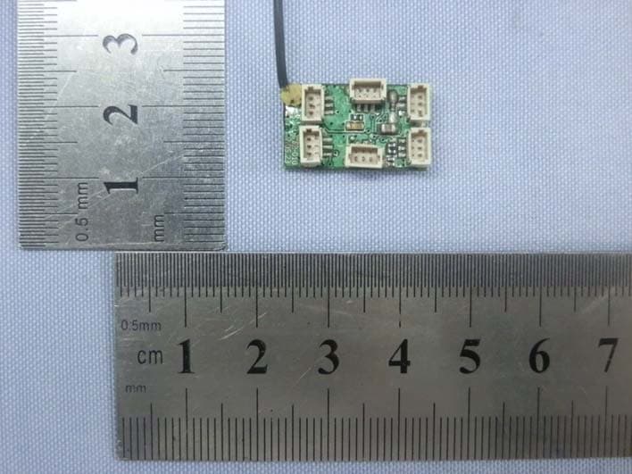
ZKZ-33565
Dec 10, 2012Slow Flyer Receiver Graupner/SJ HoTT
Equipment Class
DSS - Part 15 Spread Spectrum Transmitter
ZKZ-MC-20
Aug 26, 2012COMPUTER SYSTEM GRAUPNER/SJ HOTT
Equipment Class
DSS - Part 15 Spread Spectrum Transmitter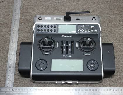
ZKZ-MC-32
Dec 21, 2011ComputerSystem Graupner HoTT
Equipment Class
DSS - Part 15 Spread Spectrum Transmitter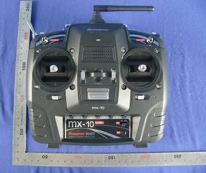
ZKZ-MX-10
Nov 20, 2011ComputerSystem Graupner HoTT
Equipment Class
DSS - Part 15 Spread Spectrum Transmitter