ZRQKB4Penclic Keyboard KB4
Penclic AB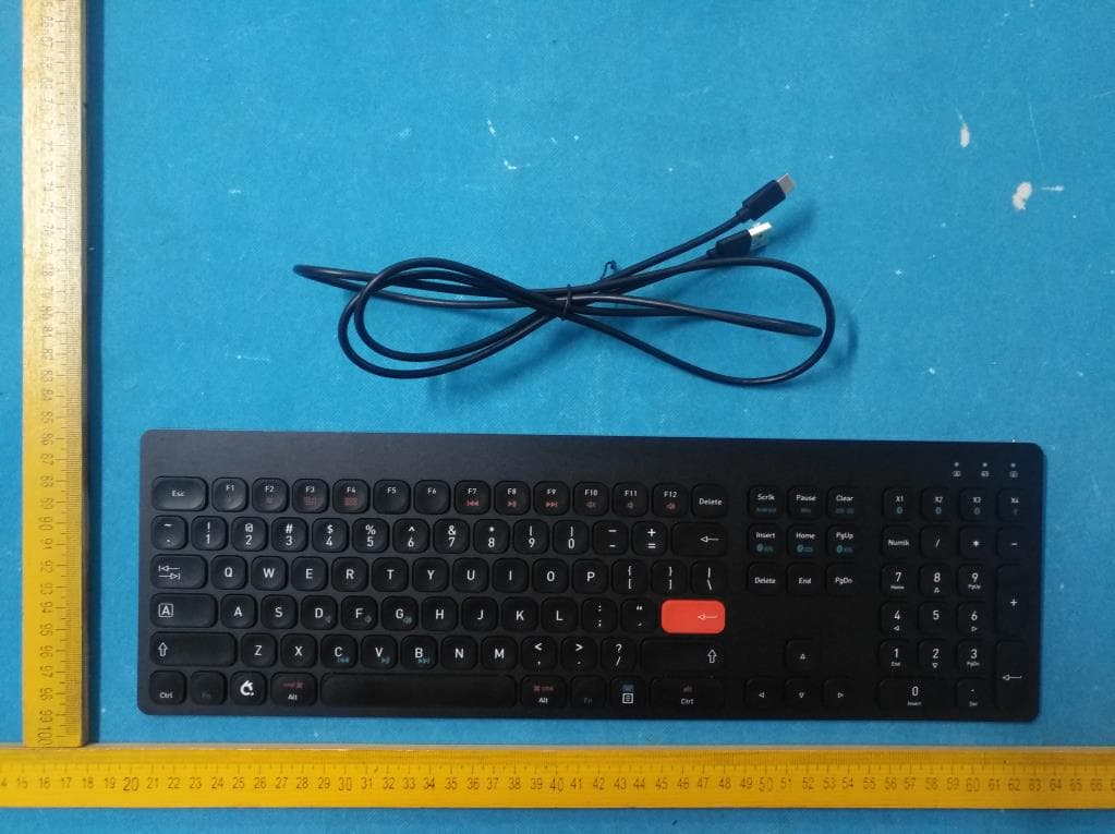
Click to zoom
Application Details
- Equipment Class
- DTS - Digital Transmission System
- Date of Grant
- Oct 08, 2020
- Application Purpose
- Original Equipment
- Date of Application
- Oct 08, 2020
- Equipment Note
- Penclic Keyboard KB4
- Frequency Range
- 2402.00000000 - 2480.00000000
- Company
- Penclic AB
- Country
- Sweden
Documents & Files
Document Text
Text extracted from the exhibit documents filed with the FCC. Open a document above to read the original.
Users Manual
User Manual Penclic KB4 Keyboard Setup With secure key handover Windows, Linux and MacOS 1. Connect device to computer via USB cable 2. Put keyboard in pairing mode by pressing Fn + X1/X2/X3 for 3 seconds 3. Start Bluetooth pairing process on your computer 4. When computer asks for pairing code, click in the input field then press any button on the KB4 keyboard, whole key will be input. 5. Done [Optional] Additional setting software available at https://penclic.se/downloads/ With normal Bluetooth security handover Windows, Linux and MacOS 1. Put keyboard in pairing mode by pressing Fn + X1/X2/X3 for 3 seconds 2. Start Bluetooth pairing process on your computer 3. When computer tells you to input code, press code on the KB4. 4. Done. [Optional] Additional setting software available at https://penclic.se/downloads/ iOS 1. Put keyboard in pairing mode by pressing Fn + Home/End/Page Down for 3 seconds 2. Start Bluetooth pairing process on your iOS device. 3. When Device tells you to input code, press code on the KB4. 4. Done. Features 1. Power switch 2. Macro Key 1 3. Macro Key 2 4. Macro Key 3 5. Macro Key 4 6. Fn, Function key Fn key combination keys: 2. Bluetooth channel 1 Tap to select, Hold 3 seconds to enter pairing mode 3. Bluetooth channel 2 4. Bluetooth channel 3 5. Connect via USB cable 7. iOS Bluetooth channel 1 8. iOS Bluetooth channel 2 9. iOS Bluetooth channel 3 10. Android 11. PC 12. iOS/MacOS 13. Mute volume 14. Volume down 15. Volume up 16. Previous song 17. Play/Pause 18. Next song 19. Numpad (support depends on OS) 20. Input language switch (support depends on OS) 21. Caps Lock indicator Light 22. Bluetooth connection (blue light), Wired connection (green light) 23. Battery status and charge indication. 24. Battery power (LED will blink once / 25% charge) Frequently asked Questions Q: Why is there a separate mode for iOS. A: iOS doesn’t support multidevice required for some multimedia functions Q: What’s the difference between the 2 Bluetooth connection modes for PC. A: The normal connection mode can potentially be intercepted if someone is listening while the pairing process is ongoing. The secure one sends the code via the cable. Q: Why USB-C to USB-A cable instead of USB-C to USB-C A: The average computer is 3-5 years old and USB-A is most common. Also too many different standards for USB-C to USB-C cable and people will assume it’s the highest performance kind. Technical specification: Bluetooth: 5.0 Bluetooth Low Energy (BLE) Range: Up to 10m Encryption: AES 256 Battery: 750mAh Lithium-ion Weight: Measurements: Cable: 2m USB-C male to USB-A male Adapter: USB-C male to USB-A female Operating systems: Windows XP or later, MacOS, Linux, iOS, Android Certifications: CE, FCC, RoHS 2.0 Technical support https://penclic.se/customer-service/ [email protected] Switchboard: +46 70 580 2140 During business hours CET time zone. Manufactured by: Penclic AB Slipgatan 7 117 39 Stockholm Sweden FCC Caution: Any changes or modifications not expressly approved by the party responsible for compliance could void the user's authority to operate this equipment. This device complies with Part 15 of the FCC Rules. Operation is subject to the following two conditions: (1) This device may not cause harmful interference, and (2) this device must accept any interference received, including interference that may cause undesired operation. NOTE: This equipment has been tested and found to comply with the limits for a Class B digital device, pursuant to part 15 of the FCC Rules. These limits are designed to provide reasonable protection against harmful interference in a residential installation. This equipment generates, uses and can radiate radio frequency energy and, if not installed and used in accordance with the instructions, may cause harmful interference to radio communications. However, there is no guarantee that interference will not occur in a particular installation. If this equipment does cause harmful interference to radio or television reception, which can be determined by turning the equipment off and on, the user is encouraged to try to correct the interference by one or more of the following measures: —Reorient or relocate the receiving antenna. —Increase the separation between the equipment and receiver. —Connect the equipment into an outlet on a circuit different from that to which the receiver is connected. —Consult the dealer or an experienced radio/TV technician for help. The device has been evaluated to meet general RF exposure requirement. The device can be used in portable condition without restriction
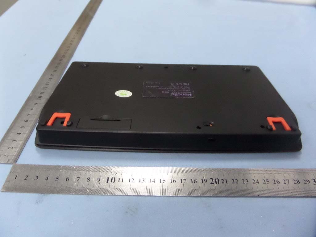
External Photos
Report No.: EC2007046RF02 Building A1, Changsha E Center, No. 18 Xiangtai Avenue, Tel.:+86-731-89634887 Liuyang Economic and Technological Development Zone, Hunan, P.R.C Fax.: +86-731-89634887 www.hn-ecloud.com Page 25 of 30 Appendix B. Photographs of EUT External Photographs Fig. 1 Fig. 2 Report No.: EC2007046RF02 Building A1, Changsha E Center, No. 18 Xiangtai Avenue, Tel.:+86-731-89634887 Liuyang Economic and Technological Development Zone, Hunan, P.R.C Fax.: +86-731-89634887 www.hn-ecloud.com Page 26 of 30 Fig. 3 Fig. 4 Report No.: EC2007046RF02 Building A1, Changsha E Center, No. 18 Xiangtai Avenue, Tel.:+86-731-89634887 Liuyang Economic and Technological Development Zone, Hunan, P.R.C Fax.: +86-731-89634887 www.hn-ecloud.com Page 27 of 30 Fig. 5 Fig. 6
Internal Photos
Report No.: EC2007046RF02 Building A1, Changsha E Center, No. 18 Xiangtai Avenue, Tel.:+86-731-89634887 Liuyang Economic and Technological Development Zone, Hunan, P.R.C Fax.: +86-731-89634887 www.hn-ecloud.com Page 26 of 30 Fig. 4 Report No.: EC2007046RF02 Building A1, Changsha E Center, No. 18 Xiangtai Avenue, Tel.:+86-731-89634887 Liuyang Economic and Technological Development Zone, Hunan, P.R.C Fax.: +86-731-89634887 www.hn-ecloud.com Page 27 of 30 Fig. 5 Fig. 6 Report No.: EC2007046RF02 Building A1, Changsha E Center, No. 18 Xiangtai Avenue, Tel.:+86-731-89634887 Liuyang Economic and Technological Development Zone, Hunan, P.R.C Fax.: +86-731-89634887 www.hn-ecloud.com Page 28 of 30 Fig.7 Fig.8 Report No.: EC2007046RF02 Building A1, Changsha E Center, No. 18 Xiangtai Avenue, Tel.:+86-731-89634887 Liuyang Economic and Technological Development Zone, Hunan, P.R.C Fax.: +86-731-89634887 www.hn-ecloud.com Page 29 of 30 Fig.9 Fig.10 Report No.: EC2007046RF02 Building A1, Changsha E Center, No. 18 Xiangtai Avenue, Tel.:+86-731-89634887 Liuyang Economic and Technological Development Zone, Hunan, P.R.C Fax.: +86-731-89634887 www.hn-ecloud.com Page 30 of 30 Fig.11 --------------------------------------------------------End of the report-------------------------------------------------------- Bluetooth Antenna
RF Exposure Info
FCC ID: ZRQKB4 FCC RF Exposure Evaluation Exposure category: General population/uncontrolled environment EUT Type: Production Unit Device Type: Portable device Refer Standard: KDB 447498 D01 General RF Exposure Guidance v06 FCC Part 2 §2.1093 Evaluation method According to KDB447498 D01 General RF Exposure Guidance v06 Section 4.3.1 Standalone SAR test exclusion considerations: “Unless specifically required by the published RF exposure KDB procedures, standalone 1-g head or body and 10-g extremity SAR evaluation for general population exposure conditions, by measurement or numerical simulation, is not required when the corresponding SAR Test Exclusion Threshold condition, listed below, is satisfied. These test exclusion conditions are based on source-based time-averaged maximum conducted output power of the RF channel requiring evaluation, adjusted for tune-up tolerance, and the minimum test separation distance required for the exposure conditions.22 The minimum test separation distance is determined by the smallest distance from the antenna and radiating structures or outer surface of the device, according to the host form factor, exposure conditions and platform requirements, to any part of the body or extremity of a user or bystander (see 5) of section 4.1). To qualify for SAR test exclusion, the test separation distances applied must be fully explained and justified by the operating configurations and exposure conditions of the transmitter and applicable host platform requirements, typically in the SAR measurement or SAR analysis report, according to the required published RF exposure KDB procedures. When no other RF exposure testing or reporting is required, a statement of justification and compliance must be included in the equipment approval, in lieu of the SAR report, to qualify for the SAR test exclusion. When required, the device specific conditions described in the other published RF exposure KDB procedures must be satisfied before applying these SAR test exclusion provisions; for example, handheld PTT two-way radios, handsets, laptops & tablets etc.23 “ [(max. power of channel, including tune-up tolerance, mW)/ (min. test separation distance, mm)] · [√f (GHz)] ≤ 3.0 for 1-g SAR and ≤ 7.5 for 10-g extremity SAR, where: • f (GHz) is the RF channel transmit frequency in GHz • Power and distance are rounded to the nearest mW and mm before calculation • The result is rounded to one decimal place for comparison • 3.0 and 7.5 are referred to as the numeric thresholds in the step 2 below The test exclusions are applicable only when the minimum test separation distance is ≤ 50 mm and for transmission frequencies between 100 MHz and 6 GHz. When the minimum test separation distance is < 5 mm, a distance of 5 mm according to 5) in section 4.1 is applied to determine SAR test exclusion. Conducted Power Results & Manufacturing tolerance Specification Operating Mode Conducted Peak Output Power (dBm) Target (dBm) Tolerance ±(dB) Bluetooth GFKS -1.42 -1 1 FCC ID: ZRQKB4 Evaluation Results Band/Mode f (GHz) Antenna Distance (mm) RF output power Evaluation Result SAR Test Exclusion Threshold SAR Test dBm mW Exclusion GFSK 2.402 5 0 1 0.31 3 Yes Remark: 1. Output power including tune up tolerance; 2. When the minimum test separation distance is < 5 mm, a distance of 5 mm according to 5) in section 4.1 is applied to determine SAR test exclusion. Conclusion The measurement results comply with the FCC Limit per 47 CFR 2.1093 for the uncontrolled RF Exposure and SAR Exclusion Threshold per KDB 447498 v06. --------------------------------------------------------End of the report--------------------------------------------------------
Test Report
RF Test Report For Penclic AB Test Standards: Part 15C Subpart C §15.247 Product Name: Penclic Keyboard KB4 Tested Model: KB4 Pro Additional Model No.: KB4 Office Brand Name: Penclic FCC ID: ZRQKB4 Classification (DTS) Digital Transmission System Report No.: EC2007046RF01 Tested Date: 2020-09-02 to 2020-09-07 Issued Date: 2020-09-07 Prepared By: Jerry Wang / Engineer Approved By: Bacon Wu / RF Manager Hunan Ecloud Testing Technology Co., Ltd. Building A1, Changsha E Center, No. 18 Xiangtai Avenue, Liuyang Economic and Technological Development Zone, Hunan, P.R.C Tel.: +86-731-89634887 Fax.: +86-731-89634887 www.hn-ecloud.com Note: The test results in this report apply exclusively to the tested model / sample. Without written approval of Hunan Ecloud Testing Technology Co., Ltd., the test report shall not be reproduced except in full. Report No.: EC2007046RF01 Building A1, Changsha E Center, No. 18 Xiangtai Avenue, Tel.:+86-731-89634887 Liuyang Economic and Technological Development Zone, Hunan, P.R.C Fax.: +86-731-89634887 FCC ID : ZRQKB4 www.hn-ecloud.com Page 2 of 75 Report Revise Record Report Version Revise Time Issued Date Valid Version Notes V1.0 / 2020.09.07 Valid Original Report Report No.: EC2007046RF01 Building A1, Changsha E Center, No. 18 Xiangtai Avenue, Tel.:+86-731-89634887 Liuyang Economic and Technological Development Zone, Hunan, P.R.C Fax.: +86-731-89634887 FCC ID : ZRQKB4 www.hn-ecloud.com Page 3 of 75 TABLE OF CONTENTS 1. TEST LABORATORY ................................................................................................................................. 5 1.1 Test facility ......................................................................................................................................... 5 2. GENERAL DESCRIPTION .......................................................................................................................... 6 2.1 Applicant ............................................................................................................................................ 6 2.2 Manufacturer ...................................................................................................................................... 6 2.3 General Description Of EUT .............................................................................................................. 6 2.4 Modification of EUT ........................................................................................................................... 7 2.5 Applicable Standards ......................................................................................................................... 7 3. TEST CONFIGURATION OF EQUIPMENT UNDER TEST ........................................................................ 8 3.1 Descriptions of Test Mode ................................................................................................................. 8 3.2 Test Mode .......................................................................................................................................... 8 3.3 Support Equipment ............................................................................................................................ 9 3.4 Test Setup ......................................................................................................................................... 9 3.5 Measurement Results Explanation Example ................................................................................... 12 4. TEST RESULT .......................................................................................................................................... 13 4.1 6dB and 99% Bandwidth Measurement .......................................................................................... 13 4.2 Peak Output Power Measurement .................................................................................................. 14 4.3 Power Spectral Density Measurement ............................................................................................ 15 4.4 Conducted Band Edges and Spurious Emission Measurement ..................................................... 16 4.5 Radiated Band Edges and Spurious Emission Measurement ........................................................ 17 4.6 AC Conducted Emission Measurement........................................................................................... 47 4.7 Antenna Requirements .................................................................................................................... 50 5. LIST OF MEASURING EQUIPMENT ........................................................................................................ 51 6. UNCERTAINTY OF EVALUATION ........................................................................................................... 53 APPENDIX A: DTS BANDWIDTH ................................................................................................................... 54 APPENDIX B: OCCUPIED CHANNEL BANDWIDTH .................................................................................... 57 APPENDIX C: MAXIMUM CONDUCTED OUTPUT POWER ......................................................................... 60 APPENDIX D: MAXIMUM POWER SPECTRAL DENSITY ............................................................................ 63 APPENDIX E: BAND EDGE MEASUREMENTS ............................................................................................ 66 APPENDIX F: CONDUCTED SPURIOUS EMISSION .................................................................................... 68 APPENDIX G: SETUP PHOTOGRAPHS ........................................................................................................ 74 Report No.: EC2007046RF01 Building A1, Changsha E Center, No. 18 Xiangtai Avenue, Tel.:+86-731-89634887 Liuyang Economic and Technological Development Zone, Hunan, P.R.C Fax.: +86-731-89634887 FCC ID : ZRQK…
Text truncated - open the document above for the full version.
Test Setup Photos
Report No.: EC2007046RF01 Building A1, Changsha E Center, No. 18 Xiangtai Avenue, Tel.:+86-731-89634887 Liuyang Economic and Technological Development Zone, Hunan, P.R.C Fax.: +86-731-89634887 FCC ID : ZRQKB4 www.hn-ecloud.com Page 74 of 75 Appendix G: Setup Photographs Fig. 1 Radiated emission setup photo(Below 30MHz) Fig. 2 Radiated emission setup photo(30MHz-1GHz) Report No.: EC2007046RF01 Building A1, Changsha E Center, No. 18 Xiangtai Avenue, Tel.:+86-731-89634887 Liuyang Economic and Technological Development Zone, Hunan, P.R.C Fax.: +86-731-89634887 FCC ID : ZRQKB4 www.hn-ecloud.com Page 75 of 75 Fig. 3 Radiated emission setup photo(Above 1GHz) Fig. 4 Power line conducted emission setup photo --------------------------------------------------------End of the report--------------------------------------------------------
Contact Information
Applicant
Olle Wahlqvist(CTO)
Technical Contact
Test Firm
Hunan Ecloud Testing Technology Co., Ltd.Bacon Wu
[email protected]+86 134 2793 2505
Technical Specifications
| # | Rule Parts | Frequency Range | Power Output |
|---|---|---|---|
| 1 | 15C | 2.40 GHz - 2.48 GHz | 700.00 µW |
Other Applications from Penclic AB
ZRQ-K3
Dec 01, 2014Penclic wireless keyboard
Equipment Class
DXX - Part 15 Low Power Communication Device Transmitter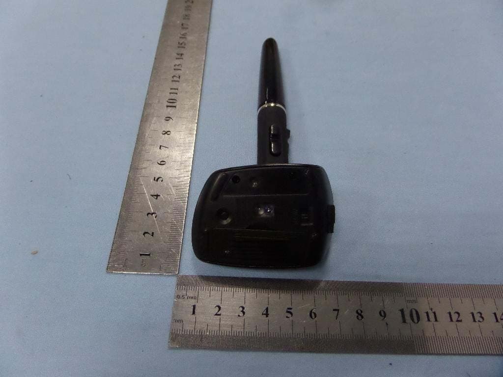
ZRQ-B4
Aug 13, 2014Penclic mouse
Equipment Class
DSS - Part 15 Spread Spectrum Transmitter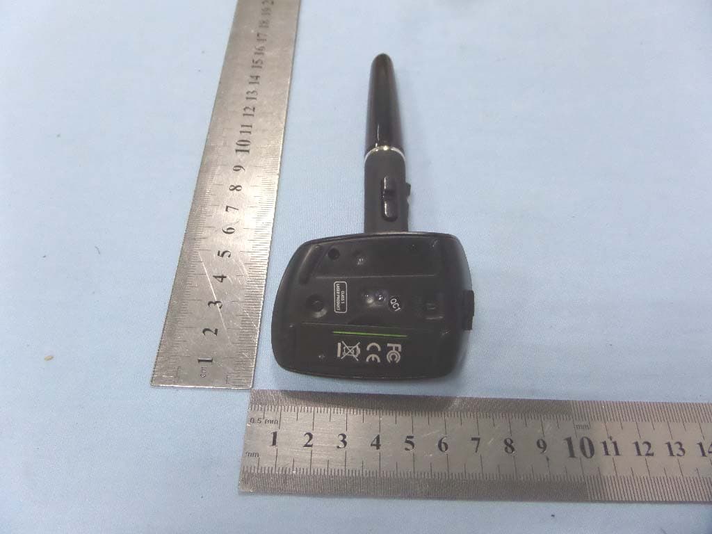
ZRQ-R5
Jun 24, 2014Penclic mouse
Equipment Class
DXX - Part 15 Low Power Communication Device Transmitter
ZRQ-R4
Mar 06, 2014PENCLIC MOUSE
Equipment Class
DXX - Part 15 Low Power Communication Device Transmitter
ZRQ-B3
Dec 03, 2013PENCLIC MOUSE
Equipment Class
DSS - Part 15 Spread Spectrum Transmitter