ZY4ABC03Motor for drive a vertical blind by RF remote control
Coulisse B.V.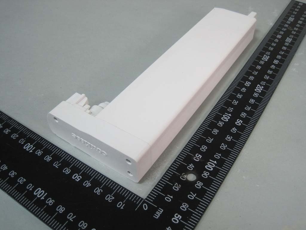
Click to zoom
Application Details
- Equipment Class
- DXX - Part 15 Low Power Communication Device Transmitter
- Date of Grant
- May 03, 2012
- Application Purpose
- Original Equipment
- Date of Application
- May 03, 2012
- Equipment Note
- Motor for drive a vertical blind by RF remote control
- Frequency Range
- 2402.00000000 - 2480.00000000
- Company
- Coulisse B.V.
- Country
- Netherlands
Documents & Files
Document Text
Text extracted from the exhibit documents filed with the FCC. Open a document above to read the original.
Users Manual
- + Coulisse B.V., Vonderweg 48, 7468 DC Enter, The Netherlands ABC-03-U_R0_ !! indoor use only 233,5 88,3 34 66,0 Online Resources For the latest information and updated manuals go to www.coulisse.nl. Obtaining Warranty Service First follow the advice in this booklet and then go to your local dealer. If the product appears to be damaged or does not function properly, go to your local dealer for instructions on how to obtain warranty service. User Manual Absolute Control Vertical Motor ABC-03 WARNING: Important safety instructions. Follow all instructions, since incorrect installation can lead to severe injury. Do not make repairs yourself. Do not attempt to open the device or disassemble it. You run the risk of electric shock and voiding the limited warranty. No user-serviceable parts are inside. WARNING: 1. General information The ABC-03 is a complete kit to motorize Vertical Absolute systems. The motorunit is always situated on the left side of the system. The motorunit is operated with a Coulisse remote control only. The software in the motorunit is selfl earning and detects its endpoints automatically. The motorunit contains a motor with a gearbox. An electronic actuator switches between sliding and rotating the slats. Sliding and rotating is possible at every position. The blinds are automatically rotated in a secure position before sliding. 1.1 General dimensions ABC-03 Powersupply12-24V DC - 3A Rated power36W Nom. translating speed1,5mtr/min Max. rotating torque680 mNm Max. pulling force3,6 Kg Max. channels to pair32 channels Operating temperature5 - 60°C 1.2 Performances 1.3 Connectors and buttons - Pair to a channel/remote (also possible by using ‘SingleSelect’, see manual Remote control*) 2. Programming and operating 2.1 Programming Set in Program mode: Shortly press program button Program mode: Blind is stepping... Choose channel by pressing the ChannelSelect button Pair/unpair by pressing the program button on the backside of the remote Exit Program mode: Shortly press program button 2.2 Operating - Manual Control - Control by remote Press program button for more than 2 sec. Blind rotates as long as button is pressed (max. 15 sec.) Exit or press program button another time for more than 2 sec. and blind moves in opposite direction Additional blind settings:Available Switch rotation directionYes Favorite positionYes BatteryModeYes We refer to the manual of the Coulisse Remote control to set the additional blind settings. 2.3 Additional blind settings Disclaimer: © Copyright Coulisse All rights reserved. No part of this publication may be reproduced, stored in a retrieval system, or transmitted, in any form, by any means, electronic, mechanical, photocopying, recording, digital or otherwise without the written permission of the publisher. Although this manual has been composed with the most care, Coulisse B.V. does not accept any responsibility for damage due to mistakes and/or faults in this manual. Coulisse B.V. reserves the right to revise the manual and to revise and/or changes its content at any time, without obligation to notify any person or entity of such revisions or changes. The most recent version replaces older versions of this manual. The most recent version is available at ww.coulisse.nl or contact your Coulisse contact person. We invite you to send remarks and comments about this manual to Coulisse at [email protected]. 2.4 Reset & initialisation - Reset to factory defaults New motors can be initialized directly without resetting Hold program button for 10 sec. untill blind stops stepping Program mode: Blind is stepping... Set in Program mode: Shortly press program button - Reset to factory defaults & Erase all paired remotes Hold program button for 15 sec. untill blind stops stepping and steps once Program mode: Blind is stepping... Set in Program mode: Shortly press program button - Initialisation (only possible after reset) 1. Connect the motorunit with the 12-24V DC - 3A powersupply 2. Detect endpositions: Shortly press program button It is important that the run- nertrain fi rst moves outwards. If not, press program button to stop and press it again to change the direction. Blind is now ready for normal use. Blind moves slowly Wait while blind is detecting the end- points... (this process will take a while and may make some noise) When blind is ready the runnertrain must be in. Check if all run- ners are aligned. If not, repeat step 1 & 2 completely. 5. Service & Support Do not make repairs yourself. Do not attempt to open the device or disassemble it. You run the risk of electric shock and voiding the limited warranty. No user-serviceable parts are inside. WARNING: 4. Safety & Cleaning 4.1 Safety 4.2 Cleaning Follow these general rules when cleaning the outside of the device and its components: - Make sure the device is unplugged. - Use a damp, soft, lint-free cloth. Avoid getting moisture in openings. - Don’t use aerosol sprays, solvents, alcohol, or abrasives. Do not make repairs yourself. Do not attempt to open the device or disassemble it. You run the risk of electric shock and voiding the limited warranty. No user-serviceable parts are inside. WARNING: - Do not let children play with the blind and/or remote control. - Only use powersupplies or batteries that comply with the specifi cations on the motor. - In case of malfunction, unplug the device or remove the batteries and contact your dealer. - Take care that the blind can move freely and is not blocked by objects. - Take care that the powersupply cable is out of reach for children. - Do not paint the device. - Keep the device dry. 3. Tips & Troubleshooting Please check www.coulisse.nl for the latest tips and troubleshooting guide (See manual Remotecontrol) 1 sec10 sec 1 sec15 sec 1 sec > 2 sec 1 sec. 1 sec. Program button Antenna 12-24V DC - 3A input GB1 12.9.2011 FCC Manual Regulatory information This device complies with Part 15 of the FCC Rules. Operation is subject to the following two condit…
Text truncated - open the document above for the full version.
External Photos
SPORTON International Inc. PAGE NUMBER : 1 OF 3 TEL : 886-2-2696-2468 ISSUED DATE : Apr. 05, 2012 FAX : 886-2-2696-2255 Photographs of EUT SPORTON International Inc. PAGE NUMBER : 2 OF 3 TEL : 886-2-2696-2468 ISSUED DATE : Apr. 05, 2012 FAX : 886-2-2696-2255 SPORTON International Inc. PAGE NUMBER : 3 OF 3 TEL : 886-2-2696-2468 ISSUED DATE : Apr. 05, 2012 FAX : 886-2-2696-2255
Internal Photos
SPORTON International Inc. PAGE NUMBER : 1 OF 10 TEL : 886-2-2696-2468 ISSUED DATE : Apr. 05, 2012 FAX : 886-2-2696-2255 Photographs of EUT SPORTON International Inc. PAGE NUMBER : 2 OF 10 TEL : 886-2-2696-2468 ISSUED DATE : Apr. 05, 2012 FAX : 886-2-2696-2255 SPORTON International Inc. PAGE NUMBER : 3 OF 10 TEL : 886-2-2696-2468 ISSUED DATE : Apr. 05, 2012 FAX : 886-2-2696-2255 SPORTON International Inc. PAGE NUMBER : 4 OF 10 TEL : 886-2-2696-2468 ISSUED DATE : Apr. 05, 2012 FAX : 886-2-2696-2255 SPORTON International Inc. PAGE NUMBER : 5 OF 10 TEL : 886-2-2696-2468 ISSUED DATE : Apr. 05, 2012 FAX : 886-2-2696-2255 SPORTON International Inc. PAGE NUMBER : 6 OF 10 TEL : 886-2-2696-2468 ISSUED DATE : Apr. 05, 2012 FAX : 886-2-2696-2255 SPORTON International Inc. PAGE NUMBER : 7 OF 10 TEL : 886-2-2696-2468 ISSUED DATE : Apr. 05, 2012 FAX : 886-2-2696-2255 SPORTON International Inc. PAGE NUMBER : 8 OF 10 TEL : 886-2-2696-2468 ISSUED DATE : Apr. 05, 2012 FAX : 886-2-2696-2255 SPORTON International Inc. PAGE NUMBER : 9 OF 10 TEL : 886-2-2696-2468 ISSUED DATE : Apr. 05, 2012 FAX : 886-2-2696-2255 SPORTON International Inc. PAGE NUMBER : 10 OF 10 TEL : 886-2-2696-2468 ISSUED DATE : Apr. 05, 2012 FAX : 886-2-2696-2255
Test Report
SPORTON International Inc. No.8, Lane 724, Bo-ai St., Jhubei City, HsinChu County 302, Taiwan, R.O.C. Ph: 886-3-656-9065 / FAX: 886-3-656-9085 / www.sporton.com.tw Report Format Version: 01 FCC RADIO TEST REPORT Applicant’s company Coulisse B.V. Applicant Address Vonderweg 48 7468 DC FCC ID ZY4ABC03 Manufacturer’s company Santa Monica Co., Ltd Manufacturer Address 18F., No.67, Sec.2, Tun-Hwa South Rd. Taipei, Taiwan Product Name Motor for drive a vertical blind by RF remote control Brand Name Coulisse Model Name ABC-03 Marketing Name Coulisse Test Rule Part(s) 47 CFR FCC Part 15 Subpart C § 15.249 Test Freq. Range 2402 ~ 2480MHz Received Date Nov. 17, 2011 Final Test Date Mar. 19, 2012 Submission Type Original Equipment Statement The test result in this report refers exclusively to the presented test model / sample. Without written approval of SPORTON International Inc., the test report shall not be reproduced except in full. The measurements and test results shown in this test report were made in accordance with the procedures and found in compliance with the limit given in ANSI C63.10-2009 and 47 CFR FCC Part 15 Subpart C. The test equipment used to perform the test is calibrated and traceable to NML/ROC. Report No.: FR1N1731 Report Format Version: 01 Page No. : i of ii FCC ID: ZY4ABC03 Issued Date : Apr. 05, 2012 Table of Contents 1. CERTIFICATE OF COMPLIANCE ......................................................................................................................... 1 2. SUMMARY OF THE TEST RESULT .......................................................................................................................... 2 3. GENERAL INFORMATION .................................................................................................................................. 3 3.1. Product Details....................................................................................................................................................................................3 3.2. Accessories .........................................................................................................................................................................................3 3.3. Table for Carrier Frequencies .............................................................................................................................................................3 3.4. Table for Test Modes ...........................................................................................................................................................................4 3.5. Table for Testing Locations..................................................................................................................................................................4 3.6. Table for Supporting Units ...................................................................................................................................................................4 3.7. Test Configurations .............................................................................................................................................................................5 4. TEST RESULT ..................................................................................................................................................... 8 4.1. AC Power Line Conducted Emissions Measurement...........................................................................................................................8 4.2. Field Strength of Fundamental Emissions Measurement ...................................................................................................................12 4.3. 20dB Spectrum Bandwidth Measurement ........................................................................................................................................17 4.4. Radiated Emissions Measurement ....................................................................................................................................................20 4.5. Band Edge Emissions Measurement .................................................................................................................................................29 4.6. Antenna Requirements .....................................................................................................................................................................32 5. LIST OF MEASURING EQUIPMENTS ................................................................................................................... 33 6. TEST LOCATION.............................................................................................................................................. 35 7. TAF CERTIFICATE OF ACCREDITATION ............................................................................................................. 36 APPENDIX A. TEST PHOTOS ........................................................................................................................ A1 ~ A6 Report No.: FR1N1731 Report Format Version: 01 Page No. : ii of ii FCC ID: ZY4ABC03 Issued Date : Apr. 05, 2012 History of This Test Report REPORT NO. VERSION DESCRIPTION ISSUED DATE FR1N1731 Rev. 01 Initial issue of report Apr. 05, 2012 47 CFR FCC Part 15 Subpart C 15.205(a) 15.209(a) Further, this requirement does not apply to intentional radiators that must be professionally installed. Report No.: FR1N1731 Report Format Version: 01 Page No. : 2 of 36 FCC ID: ZY4ABC03 Issued Date : Apr. 05, 2012 2. SUMMARY OF THE TEST RESULT Applied Standard: 47 CFR FCC Part 15 Subpart C Part Rule Section Description of Test Result Under Limit 4.1 15.207 AC Power Line Conducted Emissions Complies 21.93 dB 4.2 15.249(a) Field Strength of Fundamental Emissions Complies 18.40 dB 4.3 15.215(c) 20dB Spectrum Bandwidth Complies - 4.4 15.249(a)/(d) Radiated Emissions Complies 0.93 dB 4.5 15.249(d) Band Edge Emissions C…
Text truncated - open the document above for the full version.
Test Setup Photos
Report No.: FR1N1731 FCC ID: ZY4ABC03 Page No. : 1 of 6 Appendix A. Test Photos Report No.: FR1N1731 FCC ID: ZY4ABC03 Page No. : 2 of 6 1. Photographs of Conducted Emissions Test Configuration FRONT VIEW REAR VIEW Report No.: FR1N1731 FCC ID: ZY4ABC03 Page No. : 3 of 6 SIDE VIEW Report No.: FR1N1731 FCC ID: ZY4ABC03 Page No. : 4 of 6 2. Photographs of Radiated Emissions Test Configuration Test Configuration: 9kHz ~30MHz FRONT VIEW REAR VIEW Report No.: FR1N1731 FCC ID: ZY4ABC03 Page No. : 5 of 6 Test Configuration: 30MHz~1GHz FRONT VIEW REAR VIEW Report No.: FR1N1731 FCC ID: ZY4ABC03 Page No. : 6 of 6 Test Configuration: Above 1GHz FRONT VIEW REAR VIEW
Contact Information
Applicant
Bas Klein Tuente(Manager Engineering)
Test Firm
Sporton International Inc.Alex Chen
Technical Specifications
| # | Rule Parts | Frequency Range | Power Output |
|---|---|---|---|
| 1 | 15C | 2.40 GHz - 2.48 GHz | - |
Other Applications from Coulisse B.V.
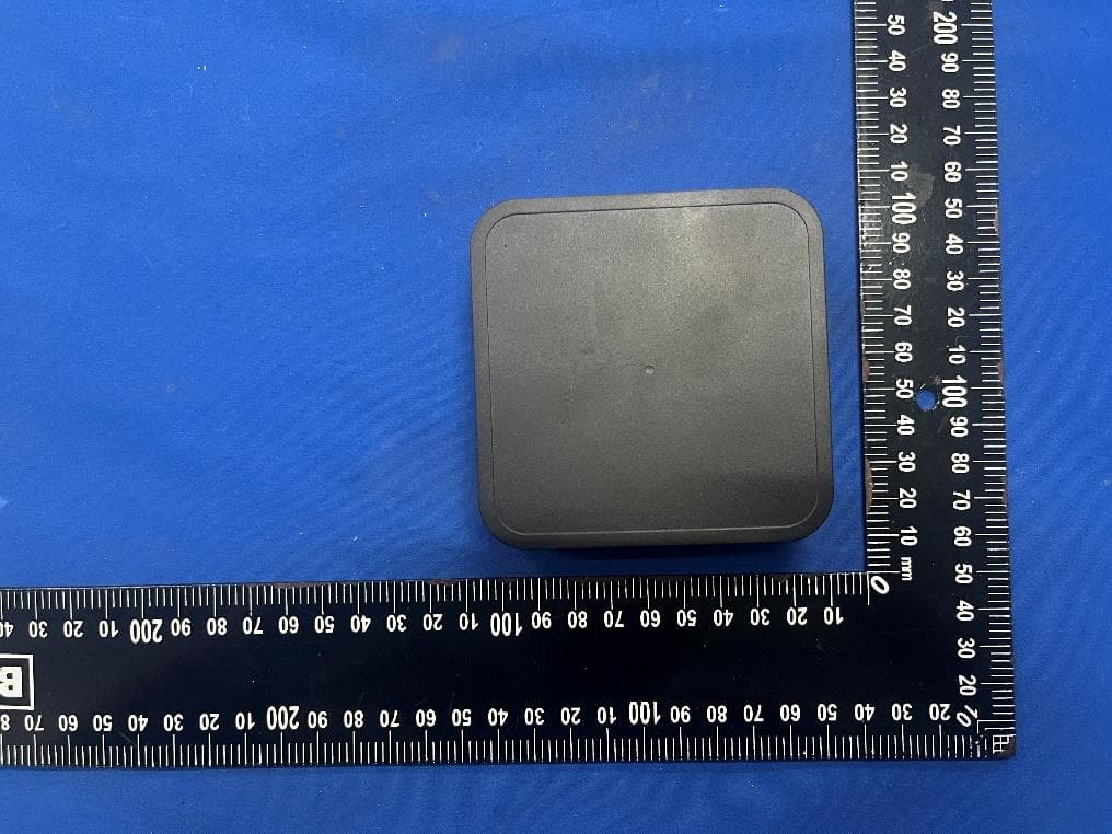
ZY4CM55
Sep 26, 2024Motionblinds Wifi Matter Bridge
Equipment Class
DSS - Part 15 Spread Spectrum Transmitter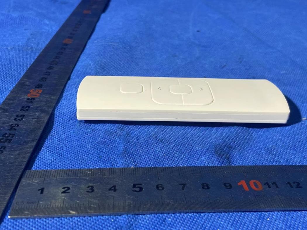
ZY4CM48
Sep 24, 2024hand-held remote with 5 channels for operating and programming blinds
Equipment Class
DSC - Part 15 Security/Remote Control Transmitter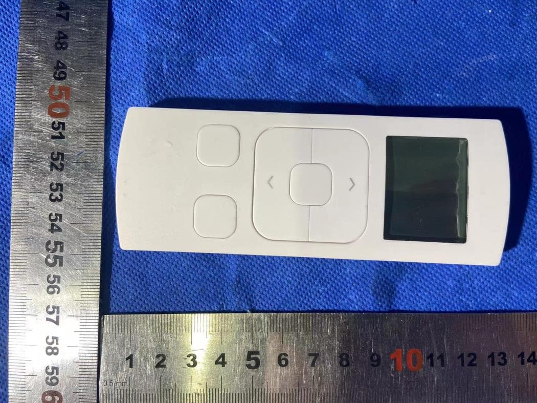
ZY4CM49
Sep 12, 2024Transmitter
Equipment Class
DSC - Part 15 Security/Remote Control Transmitter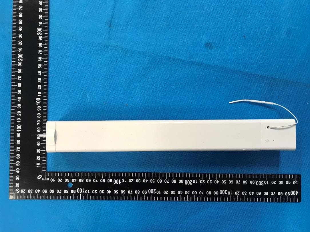
ZY4CM36B
May 18, 2023DC CURTAIN MOTOR
Equipment Class
DTS - Digital Transmission System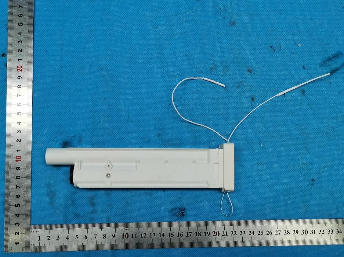
ZY4CM08E
Apr 01, 2023Honeycomb Motor
Equipment Class
DTS - Digital Transmission System