ZY4ABC05Motor for indoor blinds
Coulisse B.V.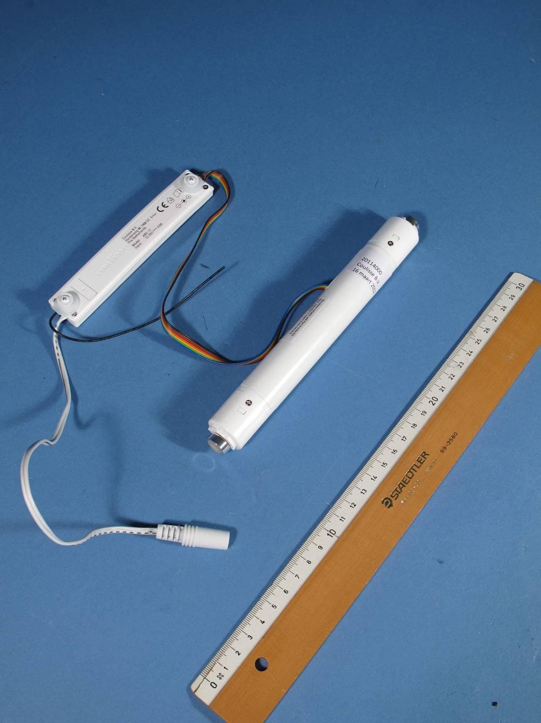
Click to zoom
Application Details
- Equipment Class
- DXT - Part 15 Low Power Transceiver, Rx Verified
- Date of Grant
- May 29, 2012
- Application Purpose
- Original Equipment
- Date of Application
- May 21, 2012
- Equipment Note
- Motor for indoor blinds
- Frequency Range
- 2402.00000000 - 2480.00000000
- Company
- Coulisse B.V.
- Country
- Netherlands
Documents & Files
Document Text
Text extracted from the exhibit documents filed with the FCC. Open a document above to read the original.
Users Manual
L3 L2 L1 Ø D1 Ø d1 - + - + 1. 2. 1. 2. Coulisse B.V., Vonderweg 48, 7468 DC Enter, The Netherlands indoor use only ABC-05-U_R0_ 1.1A User Manual DC Tubular motor ABC-05 1. General information 1.1 General dimensions The ABC-05 is a tubular motor to motorize Coulisse Absolute Roller. The tubular motor is compatible with Coulisse tubes and makes it possible to operate your blind motorised with minimum noise. The motors are operated with a Coulisse remote control only. Endpoints and favorite position are set with the remote control. The motor is energy effi cienct and can also be battery operated. WARNING: Important safety instructions. Follow all instructions, since incorrect installation can lead to severe injury. Do not make repairs yourself. Do not attempt to open the device or disassemble it. You run the risk of electric shock and voiding the limited warranty. No user-serviceable parts are inside. WARNING: 1.2 Performances 1.3 Compatibility 1.4 Connectors and buttons Program button 12-24V DC -0.6A input 2. Programming and operating 2.1 First use Step 1: Connect the motor with the 12V powersupply Program button (also possible by using ‘SingleSelect’, see manual remote control*) *Manuals are also available on our website www.coulisse.nl Step 2: Set the blind in program-mode by pushing the program button Step 3: Pair the blind to a channel/remote Choose channel by pressing the ChannelSelect button Pair/unpair by pressing the program button on the backside of the remote Press the up + down button to change the rotation direction Step 4: Switch the rotating direction Set to program mode: Shortly press program button Program mode: Blind is stepping... 1 sec Action confi rmed: blind stops stepping for 3 seconds Action confi rmed: blind stops stepping for 3 seconds If you press down and the blind goes up, the rotation direction of the blind has to be switched. Set the blind in program mode and follow this step. 12-24V DC -0.6A input We refer to the manual of the Coulisse Remote control to set the addtional blind settings. 2.4 Additional blind settings 5. Service & Support 4.2 Cleaning Follow these general rules when cleaning the outside of the device and its components: - Make sure the device is unplugged. - Use a damp, soft, lint-free cloth. Avoid getting moisture in openings. - Don’t use aerosol sprays, solvents, alcohol, or abrasives. Do not make repairs yourself. Do not attempt to open the device or disassemble it. You run the risk of electric shock and voiding the limited warranty. No user-serviceable parts are inside. WARNING: Do not make repairs yourself. Do not attempt to open the device or disassemble it. You run the risk of electric shock and voiding the limited warranty. No user-serviceable parts are inside. WARNING: - Do not let children play with the blind and/or remote control. - Only use powersupplies or batteries that comply with the specifi cations on the motor. - In case of malfunction, unplug the device or remove the batteries and contact your dealer. - Take care that the blind can move freely and is not blocked by objects. - Take care that the powersupply cable is out of reach for children. - Do not paint the device. - Keep the device dry. Online Resources For the latest information and updated manuals go to www.coulisse.nl. Obtaining Warranty Service First follow the advice in this booklet and then go to your local dealer. If the product appears to be damaged or does not function properly, go to your local dealer for instructions on how to obtain warranty service. 3. Tips & Troubleshooting Please check www.coulisse.nl for the latest tips and troubleshooting guide Disclaimer: © Copyright Coulisse All rights reserved. No part of this publication may be reproduced, stored in a retrieval system, or transmitted, in any form, by any means, electronic, mechanical, photocopying, recording, digital or otherwise without the written permission of the publisher. Although this manual has been composed with the most care, Coulisse B.V. does not accept any responsibility for damage due to mistakes and/or faults in this manual. Coulisse B.V. reserves the right to revise the manual and to revise and/or changes its content at any time, without obligation to notify any person or entity of such revisions or changes. The most recent version replaces older versions of this manual. The most recent version is available at ww.coulisse.nl or contact your Coulisse contact person . We invite you to send remarks and comments about this manual to Coulisse at [email protected]. Shortly press program button ( <2 sec. ) Program mode: Blind is stepping... - Reset to factory defaults & Erase all paired channels/remotes Hold program button for 10 sec. untill blind stops stepping 2.2 Normal use - Manual Control Hold program button for more than 2 sec. Blind moves as long as button is pressed (max. 15 sec.) For moving in opposite direction release button and hold program button again for more than 2 sec. 2.3 Reset Shortly press program button ( <2 sec. ) Program mode: Blind is stepping... - Reset to factory defaults Hold program button for 15 sec. untill blind stops stepping and steps once 1 sec 15 sec Step 6: Exit the program-mode by pressing the program button again Then set the lower endposition Step 5: Set endpositions (the positions can also be set after fi rst installation) Use the up and down buttons to go to the lower endposition Set the position by pressing the center + up button Action confi rmed: blind stops stepping for 3 seconds Action confi rmed: blind stops stepping for 3 seconds Exit program mode: Shortly press program button 1 sec 10 sec >2 sec TypePower supply Rated power Torq - rpmOperating temp. Max. channels to pair ABC-0512-24V DC0.6A - 7W0.8Nm - 28 rpm5°-60°32 channels TypeRollerVenetianOther ABC-0528, 30, 35mm-- OR Additional blind settings:Available Switch rotation directionYes Favorite positionYes BatteryModeYes 4. Safety & Cleaning Use the up and down buttons to go to the upper endp…
Text truncated - open the document above for the full version.
Users Manual
1. 2. 1. 2. indoor use only ABC-17-U_R0_ 1.1A D1 L1 L2D2 D4L3 D3 - + - + User manual Middle motor ABC-17 1. General information 1.1 General dimensions The ABC-17 is a middle motor for the motorisation of the Absolute roman blind system of Coulisse 25 mm venetian blinds and 20-25 mm pleated blinds. The motor can be operated with the Coulisse remote control only. End positions and favourite positions can be programmed with the remote control. The motor is silent, energy effi cient and equipped for the use of batteries as well for the use of solar energy. WARNING: Important safety instructions. Follow all instructions, since incorrect installation can lead to severe injury. Do not make repairs yourself. Do not attempt to open the device or disassemble it. You run the risk of electric shock and voiding the limited warranty. No user-serviceable parts are inside. WARNING: 1.2 Performances 1.3 Compatibility 1.4 Connectors and buttons Program button 12-24VDC -0.6A input 2. Programming and operating 2.1 First use Step 1: Connect the motor to 12 - 24 VDC (also possible by using ‘SingleSelect’, see manual remote control*) *Manuals are also available on our website www.coulisse.nl Step 2: Set the blind in program-mode by pushing the program button Step 3: Pair the blind to a channel/remote Choose channel by pressing the ChannelSelect button Pair/unpair by pressing the program button on the backside of the remote Press the up + down button to change the rotation direction Step 4: Draairichting veranderen Set to program mode: Shortly press program button Program mode: Blind is stepping... 1 sec Action confi rmed: blind stops stepping for 3 seconds Action confi rmed: blind stops stepping for 3 seconds If you press down and the blind goes up, the rotation direction of the blind has to be switched. Set the blind in program mode and follow this step. We refer to the manual of the Coulisse Remote control to set the addtional blind settings. 2.4 Additional blind settings 5. Service & Support 4.2 Cleaning Follow these general rules when cleaning the outside of the device and its components: - Make sure the device is unplugged. - Use a damp, soft, lint-free cloth. Avoid getting moisture in openings. - Don’t use aerosol sprays, solvents, alcohol, or abrasives. Do not make repairs yourself. Do not attempt to open the device or disassemble it. You run the risk of electric shock and voiding the limited warranty. No user-serviceable parts are inside. WARNING: Do not make repairs yourself. Do not attempt to open the device or disassemble it. You run the risk of electric shock and voiding the limited warranty. No user-serviceable parts are inside. WARNING: - Do not let children play with the blind and/or remote control. - Only use powersupplies or batteries that comply with the specifi cations on the motor. - In case of malfunction, unplug the device or remove the batteries and contact your dealer. - Take care that the blind can move freely and is not blocked by objects. - Take care that the powersupply cable is out of reach for children. - Do not paint the device. - Keep the device dry. Online Resources For the latest information and updated manuals go to www.coulisse.nl. Obtaining Warranty Service First follow the advice in this booklet and then go to your local dealer. If the product appears to be damaged or does not function properly, go to your local dealer for instructions on how to obtain warranty service. 3. Tips & Troubleshooting Please check www.coulisse.nl for the latest tips and troubleshooting guide. Disclaimer: © Copyright Coulisse All rights reserved. No part of this publication may be reproduced, stored in a retrieval system, or transmitted, in any form, by any means, electronic, mechanical, photocopying, recording, digital or otherwise without the written permission of the publisher. Although this manual has been composed with the most care, Coulisse B.V. does not accept any responsibility for damage due to mistakes and/or faults in this manual. Coulisse B.V. reserves the right to revise the manual and to revise and/or changes its content at any time, without obligation to notify any person or entity of such revisions or changes. The most recent version replaces older versions of this manual. The most recent version is available at ww.coulisse.nl or contact your Coulisse contact person. We invite you to send remarks and comments about this manual to Coulisse at [email protected]. Shortly press program button ( <2 sec. ) Program mode: Blind is stepping... - Reset to factory defaults & Erase all paired channels/remotes Hold program button for 10 sec. untill blind stops stepping 2.2 Normal use - Manual Control Hold program button for more than 2 sec. Blind moves as long as button is pressed (max. 15 sec.) For moving in opposite direction release button and hold program button again for more than 2 sec. 2.3 Resetten Shortly press program button ( <2 sec. ) Program mode: Blind is stepping... - Reset to factory defaults Hold program button for 15 sec. untill blind stops stepping and steps once 1 sec15 sec Step 6: Exit the program-mode by pressing the program button again Then set the lower endposition Step 5: Set endpositions (the positions can also be set after fi rst installation) Use the up and down buttons to go to the lower endposition Set the position by pressing the center + up button Action confi rmed: blind stops stepping for 3 seconds Action confi rmed: blind stops stepping for 3 seconds Exit program mode: Shortly press program button 1 sec10 sec >2 sec TypePower supply Rated Power Max. lifting weight Max. Torq - rpm Operating temp. Max. channels to pair ABC-17 12-24VDC 0.6A-7W4,5 kg0.8Nm-28 rpm5°-60°32 channels TypeRoman blindsVenetian blindPleated blind ABC-1735 mm25 mm20-25 mm OR Additional blind settings:Available Switch rotation directionYes Favorite positionYes BatteryMode/SolarYes 4. Safety & Cleaning Use the up and down buttons to go to the upper endposition Set the position by pressin…
Text truncated - open the document above for the full version.
Users Manual
ABC-18-A_R0_ Coulisse B.V., Vonderweg 48, 7468 DC Enter, The Netherlands 1. 2. 1. 2. 1. 2. 120 mm 25 mm 35 mm 38 mm indoor use only - + User manual Tilt-only motor 35-50 ABC-18 2. Programming and operation GB0 2.1 First use WARNING: Important safety instructions. Follow all instructions, since incorrect installation can lead to severe injury. Do not make repairs yourself. Do not attempt to open the device or disassemble it. You run the risk of electric shock and voiding the limited warranty. No user-serviceable parts are inside. WARNING: 1. General information The ABC-18 is a universal tilt-motor for 35 mm and 50 mm venetian blinds. The motor is placed in the middle of the head rail. 1.1 Dimensions Program button 12 - 24 V DC -0.6A input 2.2 Operation - Manual operation Press and hold the program button for at least 2 sec. Blind is moving as long as the button remains pressed (max. 15 sec.) In order to make the blind move in the other direction, release the button and press and hold the button once more for at least 2 sec. >2 sec See manual remote control for programming of advanced settings. 2.4 Advanced settings Advanced settings:Available Switch rotation directionYes Favourite positionYes BatteryModeYes 5. Service & Support 4. Safety & Cleaning 4.1 Safety 4.2 Cleaning Follow these general rules when cleaning the outside of the device and its components: - Make sure the device is unplugged. - Use a damp, soft, lint-free cloth. Avoid getting moisture in openings. - Don’t use aerosol sprays, solvents, alcohol, or abrasives. Do not make repairs yourself. Do not attempt to open the device or disassemble it. You run the risk of electric shock and voiding the limited warranty. No user-serviceable parts are inside. WARNING: - Do not let children play with the blind and/or remote control. - Only use powersupplies or batteries that comply with the specifi cations on the motor. - In case of malfunction, unplug the device or remove the batteries and contact your dealer. - Take care that the blind can move freely and is not blocked by objects. - Take care that the powersupply cable is out of reach for children. - Do not paint the device. - Keep the device dry. Online Resources For the latest information and updated manuals go to www.coulisse.nl. Obtaining Warranty Service First follow the advice in this booklet and then go to your local dealer. If the product appears to be damaged or does not function properly, go to your local dealer for instructions on how to obtain warranty service. 3. Tips & Troubleshooting Please check www.coulisse.nl for the latest tips and troubleshooting guide. Disclaimer: © Copyright Coulisse All rights reserved. No part of this publication may be reproduced, stored in a retrieval system, or transmitted, in any form, by any means, electronic, mechanical, photocopying, recording, digital or otherwise without the written permission of the publisher. Although this manual has been composed with the most care, Coulisse B.V. does not accept any responsibility for damage due to mistakes and/or faults in this manual. Coulisse B.V. reserves the right to revise the manual and to revise and/or changes its content at any time, without obligation to notify any person or entity of such revisions or changes. The most recent version replaces older versions of this manual. The most recent version is available at ww.coulisse.nl or contact your Coulisse contact person. We invite you to send remarks and comments about this manual to Coulisse at [email protected]. ABC-18 Power supply12-24V - 0,3 A Rated power3W Torque (rpm)0.65Nm Operating temperature5 - 60 ° Max. number of channels32 channels 1.2 Specifi cations 1.3 Power supply and buttons Step 5: Programming end positions Now program the lower position Use the up and down button to go to the lower position Confi rm the position by pressing the middle and down button Action confi rmed: blinds stop stepping for 3 sec. Exit program mode: shortly press program button Action confi rmed: blinds stop stepping for 3 sec. Use the up and down button to go to the upper position First program the upper position Step 4: Switch direction of rotation Press the up and down button at the same time to switch the direction of rotation Action confi rmed: blinds stop stepping for 3 sec. Step 3: Pair blind to channel/remote control Select channel with Channelselect button Pair/unpair by pressing the program button on the back side of the remote control Action confi rmed: blinds stop stepping for 3 sec. Step 2: Set the blind in program mode by pressing the program button (also possible with SingleSelect, See manual remote control) Program mode: blind is stepping... 1 sec Set in program mode: shortly press program button Step 1: Connect the motor to 12 - 24 V DC Shortly press program button (<2 sec.) Program mode: blind is stepping... Press and hold the program button for 10 sec. until the blind stops stepping 2.3 Reset - Reset to factory defaults 1 sec 10 sec - Reset to factory defaults & erase all paired channels/remote controls Shortly press program button (<2 sec.) Program mode: blind is stepping... Press and hold the program button for 15 sec. until the blind stops stepping and steps once again. 1 sec 15 sec Do not make repairs yourself. Do not attempt to open the device or disassemble it. You run the risk of electric shock and voiding the limited warranty. No user-serviceable parts are inside. WARNING:
Users Manual
07.05.2012 FCC Manual Regulatory information This device complies with Part 15 of the FCC Rules. Operation is subject to the following two conditions: (1) this device may not cause harmful interference, and (2) this device must accept any interference received, including interference that may cause undesired operation. FCC ID: ZY4ABC05 1 FCC Information to User This product does not contain any user serviceable components and is to be used with approved antennas only. Any product changes or modifications will invalidate all applicable regulatory certi- fications and approvals. 2 FCC Electronic Emission Notices This device complies with part 15 of the FCC Rules. Operation is subject to the following two conditions: 1. This device may not cause harmful interference 2. This device must accept any interference received, including interference that may cause unde- sired operation. 3 FCC Radio Frequency Interference statement This equipment has been tested and found to comply with the limits for a class B digital device, pursuant to Part 15 of the FCC Rules. These limits are designed to provide reasonable protection against harmful interference when the equipment is operated in a commercial environment. This equipment generates, uses and can radiate radio frequency energy and, if not installed and used in accordance with the instructions, may cause harmful interference to radio communications. Operation of this equipment in a residential area may cause harmful interference, in which case the user will be required to correct the interference at his own expense. If this equipment does cause harmful interference to radio or television reception, which can be determined by turning the equipment off and on, the user is encouraged to try to correct the interference by one or more of the following measures: • Reorient or relocate the receiving antenna • Increase the separation between the equipment and receiver • Connect the equipment into an outlet on a circuit different from that to which the receiver is connected • Consult the dealer or an experienced radio/TV technician for help
External Photos
Photographs module 20114000300 External PHOTOGRAPH 1: - OVERVIEW OF ABC-05 ........................................................................................................ 2 PHOTOGRAPH 2: - DETAIL VIEW OF ABC-05 ..................................................................................................... 3 PHOTOGRAPH 3: - DC CONNECTOR OF ABC-05 ................................................................................................ 4 PHOTOGRAPH 4: - OVERVIEW OF ABC-17 ........................................................................................................ 5 PHOTOGRAPH 5: - MOTOR OF ABC-17 ............................................................................................................. 6 PHOTOGRAPH 6: - TOP VIEW OF ABC-17 .......................................................................................................... 7 PHOTOGRAPH 7: - BOTTOM VIEW OF ABC-17 ................................................................................................... 8 PHOTOGRAPH 8: - DC CONNECTOR OF ABC-17 ................................................................................................ 9 PHOTOGRAPH 9: - OVERVIEW OF ABC-18 .......................................................................................................10 PHOTOGRAPH 10: - DETAIL OF ABC-18 ..........................................................................................................11 PHOTOGRAPH 11: - DC CONNECTORL OF ABC-18 ...........................................................................................12 Page: 2 of 12 Photograph module 20114000300 external Photograph 1: - Overview of ABC-05 Page: 3 of 12 Photograph module 20114000300 external Photograph 2: - Detail view of ABC-05 Page: 4 of 12 Photograph module 20114000300 external Photograph 3: - DC connector of ABC-05 Page: 5 of 12 Photograph module 20114000300 external Photograph 4: - Overview of ABC-17 Page: 6 of 12 Photograph module 20114000300 external Photograph 5: - Motor of ABC-17 Page: 7 of 12 Photograph module 20114000300 external Photograph 6: - Top view of ABC-17 Page: 8 of 12 Photograph module 20114000300 external Photograph 7: - Bottom view of ABC-17 Page: 9 of 12 Photograph module 20114000300 external Photograph 8: - DC connector of ABC-17 Page: 10 of 12 Photograph module 20114000300 external Photograph 9: - Overview of ABC-18 Page: 11 of 12 Photograph module 20114000300 external Photograph 10: - Detail of ABC-18 Page: 12 of 12 Photograph module 20114000300 external Photograph 11: - DC connectorl of ABC-18
ID Label/Location Info
FCC Label location ABC-05 + varianten: ABC-05 ABC-17 ABC-18
ID Label/Location Info
This device complies with Part 15 of the FCC Rules. Operation is subject to the following two conditions: (1) this device may not cause harmful interference, and (2) this device must accept any interference received, including interference that may cause undesired operation. FCC ID: ZY4ABC05 sticker size 37.5 x 25 mm
Internal Photos
Photographs module 20114000300 Internal PHOTOGRAPH 1: - MAIN PCB OF ABC-05, TOP VIEW ........................................................................................ 2 PHOTOGRAPH 2: - MAIN PCB OF ABC-05, BOTTOM VIEW ................................................................................. 3 PHOTOGRAPH 3: - MAIN PCB OF ABC-17, TOP VIEW ........................................................................................ 4 PHOTOGRAPH 4: - MAIN PCB OF ABC-17, BOTTOM VIEW ................................................................................. 5 PHOTOGRAPH 5: - MAIN PCB OF ABC-18, OVERVIEW ...................................................................................... 6 PHOTOGRAPH 6: - MAIN PCB OF ABC-18, TOP VIEW ........................................................................................ 7 PHOTOGRAPH 7: - MAIN PCB OF ABC-18, BOTTOM VIEW ................................................................................. 8 Page: 2 of 8 Photograph module 20114000300 internal Photograph 1: - Main PCB of ABC-05, top view Page: 3 of 8 Photograph module 20114000300 internal Photograph 2: - Main PCB of ABC-05, bottom view Page: 4 of 8 Photograph module 20114000300 internal Photograph 3: - Main PCB of ABC-17, top view Page: 5 of 8 Photograph module 20114000300 internal Photograph 4: - Main PCB of ABC-17, bottom view Page: 6 of 8 Photograph module 20114000300 internal Photograph 5: - Main PCB of ABC-18, overview Page: 7 of 8 Photograph module 20114000300 internal Photograph 6: - Main PCB of ABC-18, top view Page: 8 of 8 Photograph module 20114000300 internal Photograph 7: - Main PCB of ABC-18, bottom view
Test Setup Photos
Photographs module 20114000300 Test set up PHOTOGRAPH 1: TEST SETUP RADIATED EMISSIONS (0.15 - 30 MHZ) ................................................................. 2 PHOTOGRAPH 2: TEST SETUP RADIATED EMISSIONS 30-1000 MHZ) ................................................................... 3 PHOTOGRAPH 3: TEST SETUP RADIATED EMISSIONS 1-18 GHZ) ......................................................................... 4 PHOTOGRAPH 4: TEST SETUP RADIATED EMISSIONS 18 - 26 GHZ) ...................................................................... 5 PHOTOGRAPH 5: TEST SETUP CONDUCTED EMISSIONS ON DC POWER PORT ....................................................... 6 Page: 2 of 6 Photograph module 20123271300 test setup Photograph 1: Test setup radiated emissions (0.15 - 30 MHz) Page: 3 of 6 Photograph module 20123271300 test setup Photograph 2: Test setup radiated emissions 30-1000 MHz) Page: 4 of 6 Photograph module 20123271300 test setup Photograph 3: Test setup radiated emissions 1-18 GHz) Page: 5 of 6 Photograph module 20123271300 test setup Photograph 4: Test setup radiated emissions 18 - 26 GHz) Page: 6 of 6 Photograph module 20123271300 test setup Photograph 5: Test setup conducted emissions on DC power port
Contact Information
Applicant
Bas Klein Tuente(Manager Engineering)
Technical Contact
Test Firm
Kiwa Nederland B.V.Willem Jong
[email protected]+31 889983621
Technical Specifications
| # | Rule Parts | Frequency Range | Power Output |
|---|---|---|---|
| 1 | 15C | 2.40 GHz - 2.48 GHz | - |
Other Applications from Coulisse B.V.
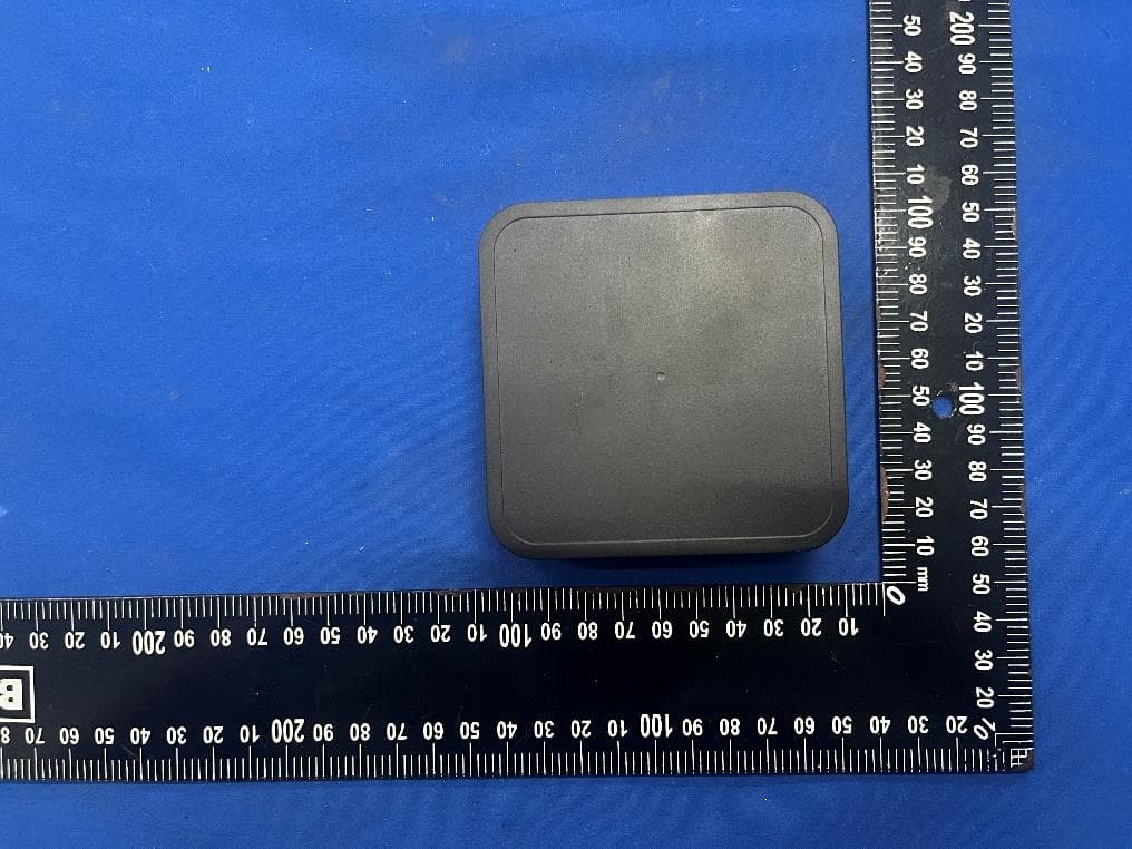
ZY4CM55
Sep 26, 2024Motionblinds Wifi Matter Bridge
Equipment Class
DSS - Part 15 Spread Spectrum Transmitter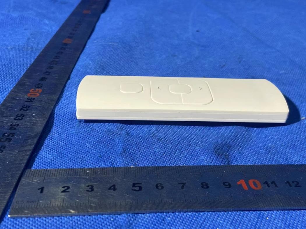
ZY4CM48
Sep 24, 2024hand-held remote with 5 channels for operating and programming blinds
Equipment Class
DSC - Part 15 Security/Remote Control Transmitter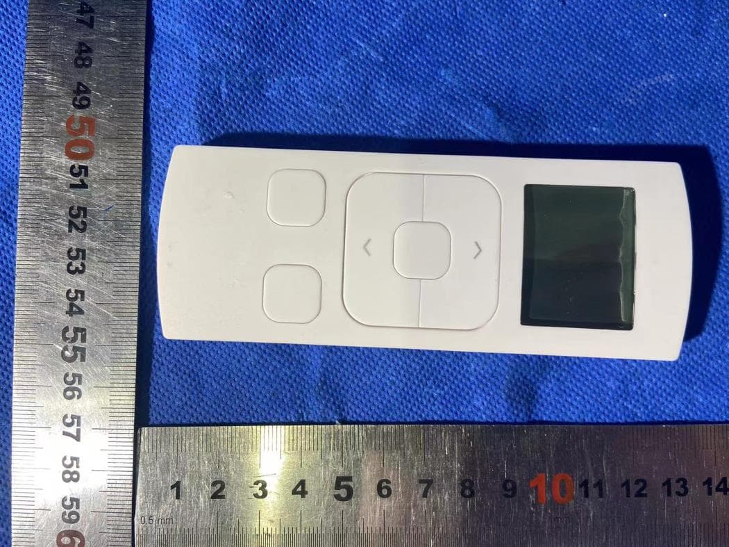
ZY4CM49
Sep 12, 2024Transmitter
Equipment Class
DSC - Part 15 Security/Remote Control Transmitter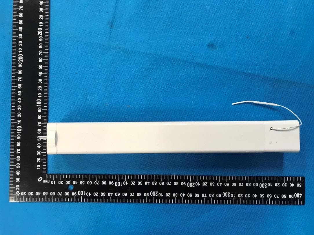
ZY4CM36B
May 18, 2023DC CURTAIN MOTOR
Equipment Class
DTS - Digital Transmission System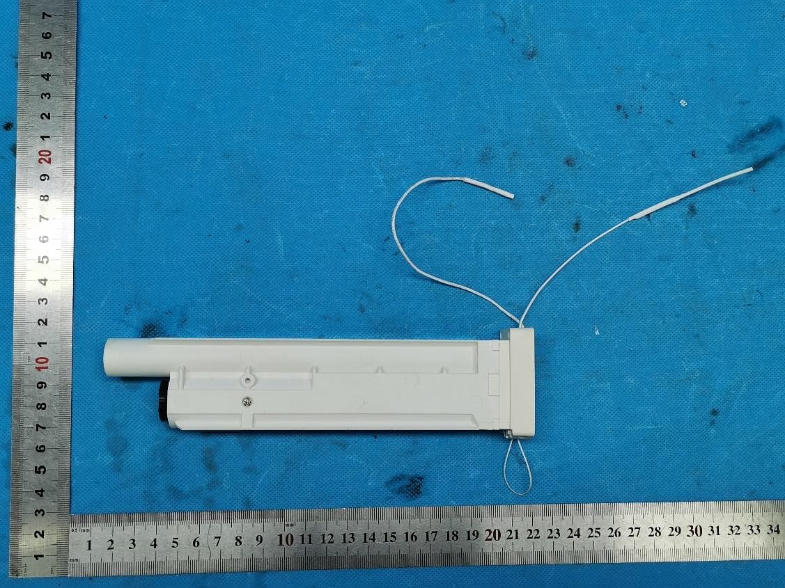
ZY4CM08E
Apr 01, 2023Honeycomb Motor
Equipment Class
DTS - Digital Transmission System