ZY4ABC06Tubular Motor
Coulisse B.V.Application Details
- Equipment Class
- DXT - Part 15 Low Power Transceiver, Rx Verified
- Date of Grant
- Jul 14, 2012
- Application Purpose
- Original Equipment
- Date of Application
- Jul 14, 2012
- Equipment Note
- Tubular Motor
- Frequency Range
- 2402.00000000 - 2480.00000000
- Company
- Coulisse B.V.
- Country
- Netherlands
Documents & Files
Document Text
Text extracted from the exhibit documents filed with the FCC. Open a document above to read the original.
Users Manual
RCU-29-ABCRCU-30-ABCRCU-32-ABCRCU-31-ABCRCU-33-ABC RCU-13RCU-13-ABCRCU-14RCU-14-ABC RTU-42 RTU-50RTU-65RTU-80 1.3A1.3B 1.3C 1.3E 1.3D RCU-29-ABC ph1 1.4A1.4B 1.4D 1.4E 1.4F 1.4G ph1 1.4C RCU-30/31/32/33-ABC RCU-13/14 ph1 ABC-0607-A_R1_ Assembly Manual AC Tubular motors ABC-06, -07 - MC Motor ABC-06/ABC-07 System:Tube:Drive plug:Adapter: Roller 42mmRTU-42 RCU-29-ABCno adapters Roller 50mmRTU-50 RCU-29-ABCno adapters Roller 65mmRTU-65 RCU-30-ABCRCU-13 Roller 80mmRTU-80 RCU-31-ABCRCU-14 1. Assembly 1.1 Compatibility and adapters Drive plugs: 1.2 Component overview 1.3 Motor assembly Roller 42/50mm Adapters: Tubes: GB1 1.4 Motor assembly Roller 65/80mm indoor use only L3 L2 Ø D1 L1 ! Coulisse B.V., Vonderweg 48, 7468 DC Enter, The Netherlands ! ABC-0607MC-U_R1_ User Manual AC Tubular motors ABC-06, -07 - MC(120) WARNING: Important safety instructions. Follow all instructions, since incorrect installation can lead to severe injury. Do not make repairs yourself. Do not attempt to open the device or disassemble it. You run the risk of electric shock and voiding the limited warranty. No user-serviceable parts are inside. WARNING: 1. General information The ABC-06-MC(120), ABC-07-MC(120) are tubular motors to motorize Coulisse Absolute Roller. The tubular motors are compatible with Coulisse tubes and makes it possible to operate your blind motorised with minimum noise. TypePower supply Rated power Torq - rpmMax. revolutions Weight [gram] IP ABC-06-MC230V AC 50Hz 0.53A - 121W 5Nm - 30 rpm30175044 ABC-07-MC230V AC 50Hz 0.53A - 121W 10Nm - 15 rpm30175044 ABC-06-MC(120) 120V AC 60Hz 0.85A - 102W 6Nm - 33 rpm30175044 ABC-07-MC(120) 120V AC 60Hz0.89A - 92W 10Nm - 21 rpm30175044 1.2 Performances 2. Connecting diagram Do not make repairs yourself. Do not attempt to open the device or disassemble it. You run the risk of electric shock and voiding the limited warranty. No user-serviceable parts are inside. WARNING: - Do not let children play with the blind and/or remote control. - Only use powersupplies or batteries that comply with the speci cations on the motor. - In case of malfunction, unplug the device or remove the batteries and contact your dealer. - Take care that the blind can move freely and is not blocked by objects. - Take care that the powersupply cable is out of reach for children. - Do not paint the device. - Keep the device dry. 6. Service & Support Follow these general rules when cleaning the outside of the device and its components: - Make sure the device is unplugged. - Use a damp, soft, lint-free cloth. Avoid getting moisture in openings. - Don’t use aerosol sprays, solvents, alcohol, or abrasives. Do not make repairs yourself. Do not attempt to open the device or disassemble it. You run the risk of electric shock and voiding the limited warranty. No user-serviceable parts are inside. WARNING: Online Resources For the latest information and updated manuals go to www.coulisse.nl. Obtaining Warranty Service First follow the advice in this booklet and then go to your local dealer. If the product appears to be damaged or does not function properly, go to your local dealer for instructions on how to obtain warranty service. 4. Tips & Troubleshooting Please check www.coulisse.nl for the latest tips and troubleshooting guide Disclaimer: © Copyright Coulisse All rights reserved. No part of this publication may be reproduced, stored in a retrieval system, or transmitted, in any form, by any means, electronic, mechanical, photocopying, recording, digital or otherwise without the written permission of the publisher. Although this manual has been composed with the most care, Coulisse B.V. does not accept any responsibility for damage due to mistakes and/or faults in this manual. Coulisse B.V. reserves the right to revise the manual and to revise and/or changes its content at any time, without obligation to notify any person or entity of such revisions or changes. The most recent version replaces older versions of this manual. The most recent version is available at ww.coulisse.com or contact your Coulisse contact person . We invite you to send remarks and comments about this manual to Coulisse at [email protected]. 5. Safety & Cleaning TypeRollerVenetianOther namor-mm08 ,56 ,05 ,24)021(CM-60-CBA ABC-07-MC(120) 42, 50, 65, 80mm50mm tilt and liftroman 1.3 Compatibility IMPORTANT: When the mains cable is permanently connected, a readily accessible disconnect device shall be incorporated external to the motor. When there is a pluggable connecter installed on the mains cable, the socket-outlet shall be installed near the motor and shall be easily accessible. 1.1 General dimensions Mains cable230V120V Neutral (1)BlueWhite Direction 1 (2)BrownRed Direction 2 (3)BlackBlack Ground (4)Green/YellowGreen General Max. operating time4 min. Operating Temp.5 - 60°C rtm 2eriw htgneL 1. Do not wire two or more motors to one single pole switch or relay. 2. Do not control one motor from several locations without using a proper controller. 3. Do not connect the brown wire and the black wire at the same time to the powersource, this may permanently damage the motor. Attention: T M MS 1 M S 2 C 1 2 3 4 3. Position adjustment 2. Lower position Turn the switch downwards and turn the white or red screw until the blind has reached the lower position (select the white o r red screw depending on the position of the motor in the blind; you need to rst test this in order to make the selection). The lower position is now set. 1. Upper position Turn the switch upwards and turn the white or red screw until the blind has reached the upper position (select the white or red screw depending on the position of the motor in the blind; you need to rst test this in order to make the selection). The upper position is now set. 3. Changing positions: By turning the red or the white screw to the right (+) or to the left you can respectively enlarge the end position or make it smaller. Switch Lower position Upper position GB1 Type L1L2 L3 Ø …
Text truncated - open the document above for the full version.
Cover Letter(s)
May 31, 2012 To: SIEMIC, INC. 2206 Ringwood Avenue, San Jose, CA 95131 USA Dear Sir/Madam, Re: Project and Product Certification Representative Authorization Letter We, ______ Coulisse B.V. ___hereby authorize SIEMIC, INC. to act as a Certification Body for certifying for the following project(s): Product Description: Tubular motor Model name: ABC-06-QC120, ABC-07-QC120 We affirm that between SIEMIC and _ Coulisse B.V. __, any difference in understanding, including test plan, measurement methods, applicable standards and relevant procedures and processes have been resolved prior to commencement of testing activities. Sincerely,
Cover Letter(s)
SCS-F19: Confidentiality Request Letter Page 1 of 1 Rev 2.0 May 31, 2012 To: Federal Communications Commission Authorization and Evaluation Division 7435 Oakland Mills Road Columbia, MD Confidentiality Request regarding application for certification of FCC ID: ZY4ABC06 We hereby request confidential treatment of information accompanying this application as outlined below: - Block Diagram - Operational Description - Schematic The above materials contain trade secrets and proprietary information not customarily released to the public. The public disclosure of these materials may be harmful to the applicant and provide unjustified benefits to its competitors. The applicant understands that pursuant to Section 0.457 & 0.459 of the Rules, disclosure of this application and all accompanying documentation will not be made before the date of the Grant for this application.
ID Label/Location Info
FCC Certification label Sample
ID Label/Location Info
FCC Certification Label Location Sample Label location
Internal Photos
Antenna
Test Report
Page 1 of 58 FCC ID: ZY4ABC06 ACCURATE TECHNOLOGY CO. LTD REPORT NO. ATE20121024 FCC CERTIFICATION On Behalf of Coulisse B.V. Tubular motor Model No.: ABC-06-QC120, ABC-07-QC120 FCC ID: ZY4ABC06 Prepared for : Coulisse B.V. Address : Vonderweg 48, Enter, Netherlands Prepared by : ACCURATE TECHNOLOGY CO. LTD Address : F1, Bldg. A, Changyuan New Material Port, Keyuan Rd. Science & Industry Park, Nanshan, Shenzhen, Guangdong P.R. China Tel: (0755) 26503290 Fax: (0755) 26503396 Report Number : ATE20121024 Date of Test : May 28-31, 2012 Date of Report : May 31, 2012 Page 2 of 58 FCC ID: ZY4ABC06 ACCURATE TECHNOLOGY CO. LTD REPORT NO. ATE20121024 TABLE OF CONTENTS Description Page Test Report Certification 1. GENERAL INFORMATION .......................................................................................................... 4 1.1. Description of Device (EUT)....................................................................................................................4 1.2. Description of Test Facility ......................................................................................................................5 1.3. Measurement Uncertainty.........................................................................................................................6 2. MEASURING DEVICE AND TEST EQUIPMENT ..................................................................... 7 3. SUMMARY OF TEST RESULTS................................................................................................... 8 4. FUNDAMENTAL AND HARMONICS RADIATED EMISSION FOR SECTION 15.249(A) 9 4.1. Block Diagram of Test Setup....................................................................................................................9 4.2. The Emission Limit ................................................................................................................................10 4.3. Configuration of EUT on Measurement .................................................................................................10 4.4. Operating Condition of EUT ..................................................................................................................10 4.5. Test Procedure ........................................................................................................................................11 4.6. The Field Strength of Radiation Emission Measurement Results ..........................................................12 5. SPURIOUS RADIATED EMISSION FOR SECTION 15.249(D) ............................................. 15 5.1. Block Diagram of Test Setup..................................................................................................................15 5.2. The Emission Limit For Section 15.249(d) ............................................................................................16 5.3. EUT Configuration on Measurement .....................................................................................................16 5.4. Operating Condition of EUT ..................................................................................................................17 5.5. Test Procedure ........................................................................................................................................17 5.6. The Emission Measurement Result ........................................................................................................18 6. BAND EDGES ................................................................................................................................. 21 6.1. The Requirement ....................................................................................................................................21 6.2. EUT Configuration on Measurement .....................................................................................................21 6.3. Operating Condition of EUT ..................................................................................................................21 6.4. Test Procedure ........................................................................................................................................21 6.5. The Measurement Result ........................................................................................................................22 7. AC POWER LINE CONDUCTED EMISSION FOR FCC PART 15 SECTION 15.207(A) .. 24 7.1. Block Diagram of Test Setup..................................................................................................................24 7.2. The Emission Limit ................................................................................................................................24 7.3. Configuration of EUT on Measurement .................................................................................................25 7.4. Operating Condition of EUT ..................................................................................................................25 7.5. Test Procedure ........................................................................................................................................25 7.6. Power Line Conducted Emission Measurement Results ........................................................................26 8. ANTENNA REQUIREMENT........................................................................................................ 27 8.1. The Requirement ....................................................................................................................................27 8.2. Antenna Construction .............................................................................................................................27 Page 3 of 58 FCC ID: ZY4ABC06 ACCURATE TECHNOLOGY CO. LTD REPORT NO. ATE20121024 Test Report Certification Applicant : Coulisse B.V. Manufacturer : NINGBO DOOYA MECHANIC & ELECTRONIC TECHNOLOGY CO., LTD EUT Description : Tub…
Text truncated - open the document above for the full version.
Test Setup Photos
Conducted emissions test Radiated emissions test < 30MHz Radiated emissions test < 1GHz Radiated emissions test > 1GHz
Contact Information
Applicant
Bas Klein Tuente(Manager Engineering)
Test Firm
Accurate Technology Co., Ltd.Sean Liu
Technical Specifications
| # | Rule Parts | Frequency Range | Power Output |
|---|---|---|---|
| 1 | 15C | 2.40 GHz - 2.48 GHz | - |
Other Applications from Coulisse B.V.
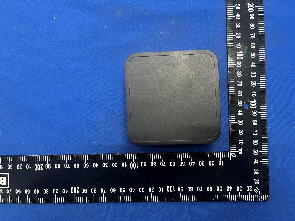
ZY4CM55
Sep 26, 2024Motionblinds Wifi Matter Bridge
Equipment Class
DSS - Part 15 Spread Spectrum Transmitter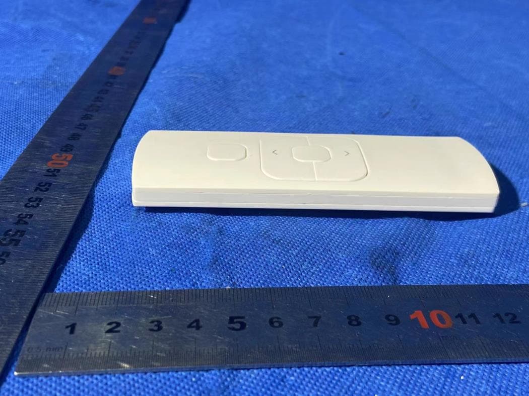
ZY4CM48
Sep 24, 2024hand-held remote with 5 channels for operating and programming blinds
Equipment Class
DSC - Part 15 Security/Remote Control Transmitter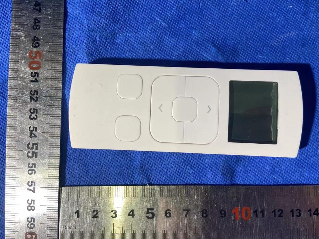
ZY4CM49
Sep 12, 2024Transmitter
Equipment Class
DSC - Part 15 Security/Remote Control Transmitter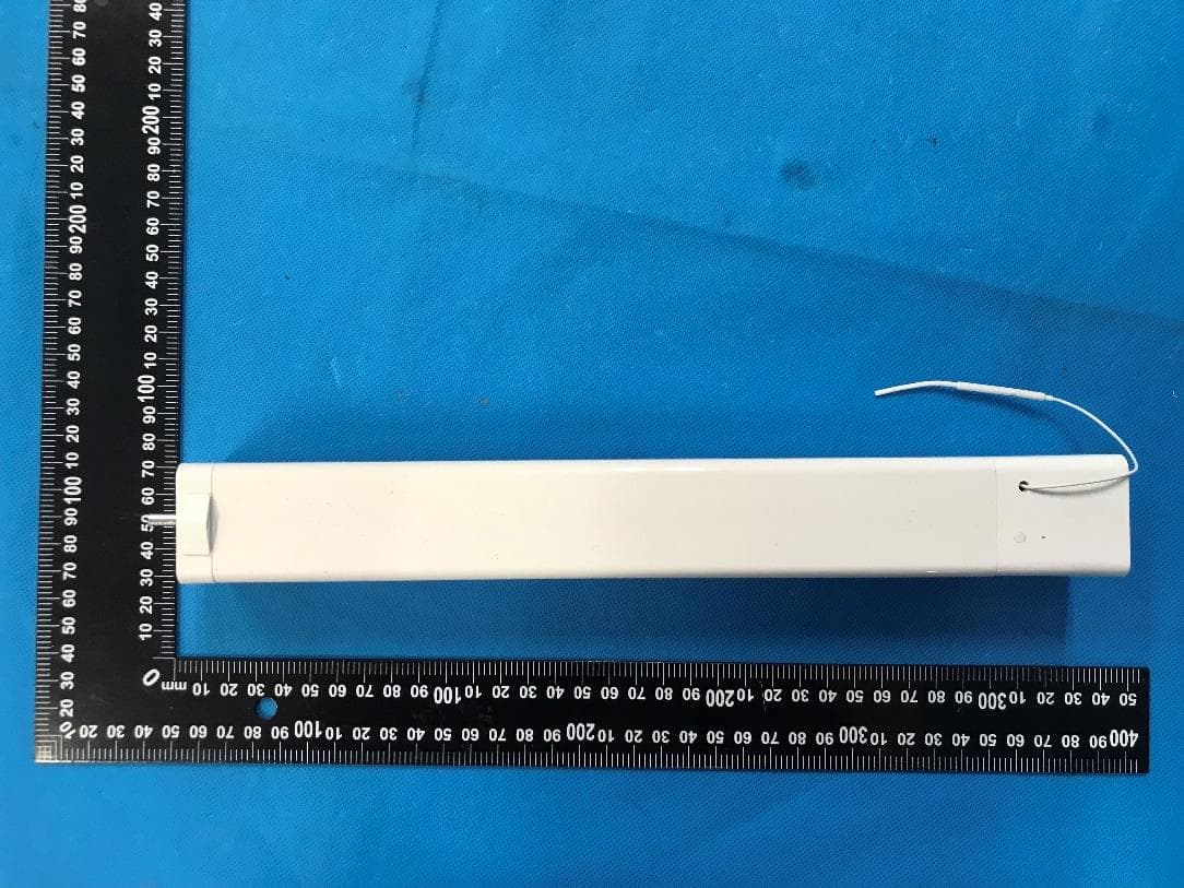
ZY4CM36B
May 18, 2023DC CURTAIN MOTOR
Equipment Class
DTS - Digital Transmission System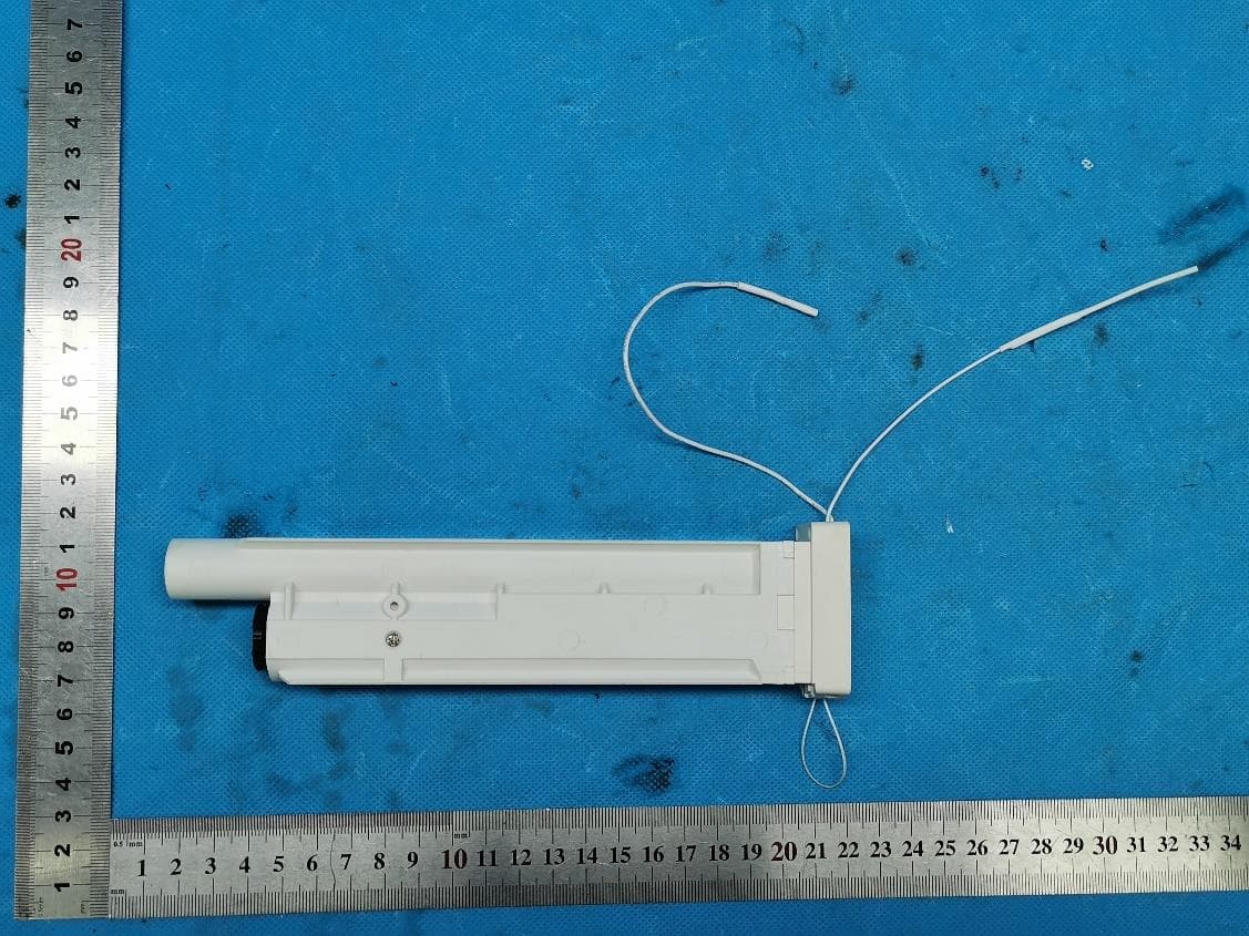
ZY4CM08E
Apr 01, 2023Honeycomb Motor
Equipment Class
DTS - Digital Transmission System