ZY4ABC22Device for receiving and sending signals for indoor blinds
Coulisse B.V.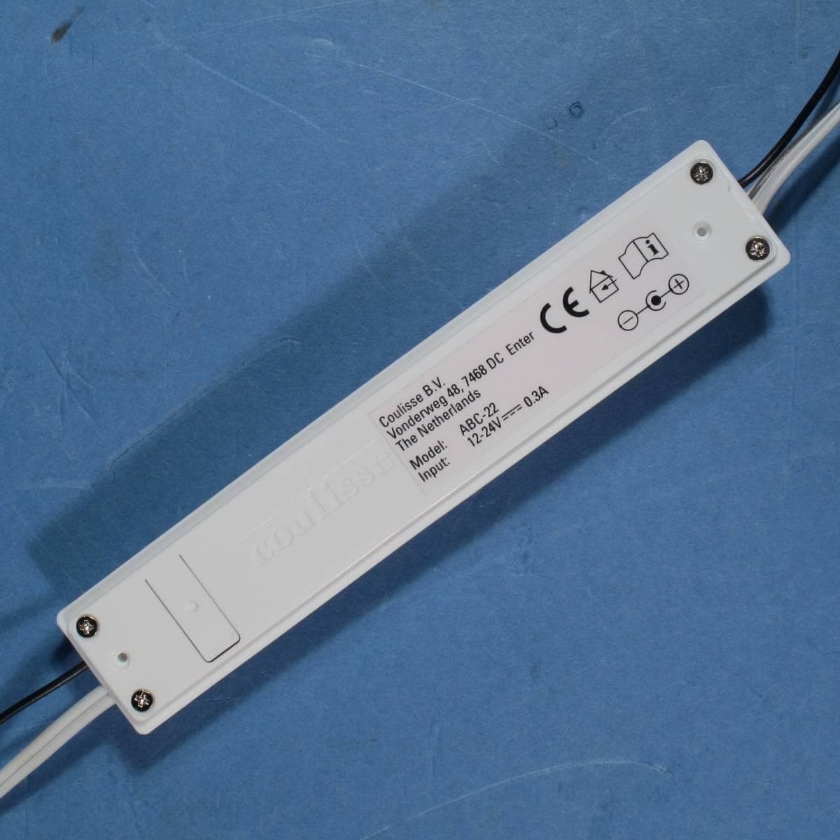
Click to zoom
Application Details
- Equipment Class
- DXX - Part 15 Low Power Communication Device Transmitter
- Date of Grant
- Jan 26, 2014
- Application Purpose
- Original Equipment
- Date of Application
- Jan 23, 2014
- Equipment Note
- Device for receiving and sending signals for indoor blinds
- Frequency Range
- 2402.00000000 - 2480.00000000
- Company
- Coulisse B.V.
- Country
- Netherlands
Documents & Files
Document Text
Text extracted from the exhibit documents filed with the FCC. Open a document above to read the original.
Users Manual
07.05.2012 FCC Manual Regulatory information This device complies with Part 15 of the FCC Rules. Operation is subject to the following two conditions: (1) this device may not cause harmful interference, and (2) this device must accept any interference received, including interference that may cause undesired operation. FCC ID: ZY4ABC22 1 FCC Information to User This product does not contain any user serviceable components and is to be used with approved antennas only. Any product changes or modifications will invalidate all applicable regulatory certi- fications and approvals. 2 FCC Electronic Emission Notices This device complies with part 15 of the FCC Rules. Operation is subject to the following two conditions: 1. This device may not cause harmful interference 2. This device must accept any interference received, including interference that may cause unde- sired operation. 3 FCC Radio Frequency Interference statement This equipment has been tested and found to comply with the limits for a class B digital device, pursuant to Part 15 of the FCC Rules. These limits are designed to provide reasonable protection against harmful interference when the equipment is operated in a commercial environment. This equipment generates, uses and can radiate radio frequency energy and, if not installed and used in accordance with the instructions, may cause harmful interference to radio communications. Operation of this equipment in a residential area may cause harmful interference, in which case the user will be required to correct the interference at his own expense. If this equipment does cause harmful interference to radio or television reception, which can be determined by turning the equipment off and on, the user is encouraged to try to correct the interference by one or more of the following measures: • Reorient or relocate the receiving antenna • Increase the separation between the equipment and receiver • Connect the equipment into an outlet on a circuit different from that to which the receiver is connected • Consult the dealer or an experienced radio/TV technician for help
External Photos
Photographs module 20134514300 External PHOTOGRAPH 1: - TEST SAMPLE OF ABC-22, TOP VIEW .................................................................................... 2 PHOTOGRAPH 2: - TEST SAMPLE OF ABC-22, BOTTOM VIEW .............................................................................. 3 PHOTOGRAPH 3: - AC MAINS POWER SUPPLY, TYPE E018-06D .......................................................................... 4 Page: 2 of 4 Report number: 20134514300 Photograph 1: - Test sample of ABC-22, top view Page: 3 of 4 Report number: 20134514300 Photograph 2: - Test sample of ABC-22, bottom view Page: 4 of 4 Report number: 20134514300 Photograph 3: - AC mains power supply, type E018-06D
ID Label/Location Info
FCC Label location ABC-22: ABC-22
Internal Photos
Photographs module 20134514300 Internal PHOTOGRAPH 1: - INTERNAL VIEW OF ABC-22 PCB ......................................................................................... 2 PHOTOGRAPH 2: - TOP VIEW OF ABC-22 PCB.................................................................................................. 3 PHOTOGRAPH 3: - BOTTOM VIEW OF ABC-22 PCB ........................................................................................... 4 Page: 2 of 4 Report number: 20134514300 Photograph 1: - Internal view of ABC-22 PCB Page: 3 of 4 Report number: 20134514300 Photograph 2: - Top view of ABC-22 PCB Page: 4 of 4 Report number: 20134514300 Photograph 3: - Bottom view of ABC-22 PCB
Test Report
Radio test report 20134514300 based on: - FCC part 15, subpart C; sections 15.231, 15.249 & 15.207 (10-1-12 edition) - FCC part 15, subpart B; sections 15.107 & 15.109 (10-1-12 edition) Protocol exchanger between 2.4GHz Coulisse protocol and BTX 433.92MHz protocol TransferBox ABC-22 Report number: 20134514300 Contents MAIN MODULE .............................................................................................................................................. 3 1 ...... INTRODUCTION ...................................................................................................................................... 3 2 ...... PRODUCT ............................................................................................................................................... 4 3 ...... TEST SCHEDULE ..................................................................................................................................... 4 4 ...... PRODUCT DOCUMENTATION ................................................................................................................... 4 5 ...... OBSERVATIONS AND COMMENTS ........................................................................................................... 5 6 ...... MODIFICATIONS TO THE SAMPLE ............................................................................................................ 6 7 ...... SUMMARY.............................................................................................................................................. 6 8 ...... CONCLUSIONS ........................................................................................................................................ 7 TEST RESULTS MODULE ............................................................................................................................ 8 1 ...... GENERAL INFORMATION ........................................................................................................................ 8 1.1 Equipment information ..................................................................................................................... 8 1.2 Summary of tests ............................................................................................................................... 9 2 ...... EMISSION TESTS ................................................................................................................................... 10 2.1 Field strength of intentional signal (433 MHz) ............................................................................... 10 2.2 Field strength of intentional signal (2.4 GHz) ................................................................................. 11 2.3 Conducted disturbance measurements ............................................................................................ 12 2.4 Bandwidth of the emissions (433 MHz) ......................................................................................... 16 2.5 Field strength of spurious emissions 30 - 1000 MHz (433 MHz) ................................................... 17 2.6 Field strength of spurious emissions > 1000 MHz (433 MHz) ....................................................... 23 2.7 Field strength of spurious emissions 30 - 1000 MHz (2.4 GHz)..................................................... 28 2.8 Field strength of spurious emissions > 1000 MHz (2.4 GHz) ......................................................... 32 USED TEST EQUIPMENT MODULE ........................................................................................................ 39 REVISION HISTORY ................................................................................................................................... 41 Page: 3 of 41 Main module Report number: 20134514300 Main module 1 Introduction This report contains the result of tests performed by: Telefication B.V. Edisonstraat 12a 6902 PK Zevenaar The Netherlands Telefication complies with the accreditation criteria for test laboratories as laid down in ISO/IEC 17025:2005. The accreditation covers the quality system of the laboratory as well as the specific activities as described in the authorized annex bearing the accreditation number L021 and is granted on 30 November 1990 by the Dutch Council For Accreditation (RvA: Raad voor Accreditatie) . Telefication is designated by the FCC as an Accredited Test Firm for compliance testing of equipment subject to Certification under Parts 15 & 18. The Registration Number is: 282250. The Industry Canada number for the Open Area Test Site of Telefication is: 4173A-1. The contents of this test report, if reproduced, shall be copied in full, unless special consent in writing for reproduction in part is granted by Telefication. Copyright of this test report is reserved to Telefication. Ordering party: Company name : Coulisse B.V. Address : Vonderweg 48 Zipcode : 7468 DC City/town : Enter Country : The Netherlands Date of order : 3 October 2013 Page: 4 of 41 Main module Report number: 20134514300 2 Product A sample of the following product was submitted for testing: Product description : Protocol exchanger between 2.4GHz Coulisse protocol and BTX 433.92MHz protocol Manufacturer : Coulisse BV Trade mark : TransferBox Type designation : ABC-22 FCC ID : ZY4ABC22 Hardware version : -- Software release : -- Serial number : -- 3 Test schedule Tests were carried out in accordance with the specification detailed in chapter 7 “Summary” of this report. Tests were carried out at the following location: Telefication, Zevenaar (registered as an accredited test laboratory with designation number NL0001 under the US-EU MRA) The sample of the product was received on: 8 November 2013 Tests were carried out between: 8 and 11 November 2013 4 Product documentation For production of this report the following product documentation was used: Identification Date Transferbox BTX block.pdf 2012 12 05 Transferbox schematic +…
Text truncated - open the document above for the full version.
Test Setup Photos
Photographs module 20134514300 Test set up PHOTOGRAPH 1: - TEST SETUP RADIATED EMISSIONS 30 - 1000 MHZ ................................................................ 2 PHOTOGRAPH 2: - TEST SETUP RADIATED EMISSIONS 1 – 18 GHZ ...................................................................... 3 PHOTOGRAPH 3: - TEST SETUP RADIATED EMISSIONS 18 – 26 GHZ .................................................................... 4 PHOTOGRAPH 4: - TEST SETUP CONDUCTED EMISSIONS 0.15 – 30 MHZ ............................................................. 5 Page: 2 of 5 Report number: 20134514300 Photograph 1: - Test setup radiated emissions 30 - 1000 MHz Page: 3 of 5 Report number: 20134514300 Photograph 2: - Test setup radiated emissions 1 – 18 GHz Page: 4 of 5 Report number: 20134514300 Photograph 3: - Test setup radiated emissions 18 – 26 GHz Page: 5 of 5 Report number: 20134514300 Photograph 4: - Test setup conducted emissions 0.15 – 30 MHz
Contact Information
Applicant
Bas Klein Tuente(Manager Engineering)
Technical Contact
Xipas B.V.Carlo Cradussen
31 344611449
Netherlands
Non-Technical Contact
Coulisse B.V.Bas Klein Tuente
51 547855555
Test Firm
Kiwa Nederland B.V.Willem Jong
[email protected]+31 889983621
Technical Specifications
| # | Rule Parts | Frequency Range | Power Output |
|---|---|---|---|
| 1 | 15C | 2.40 GHz - 2.48 GHz | 1.00 mW |
Other Applications from Coulisse B.V.
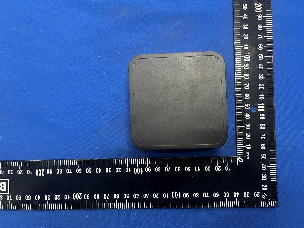
ZY4CM55
Sep 26, 2024Motionblinds Wifi Matter Bridge
Equipment Class
DSS - Part 15 Spread Spectrum Transmitter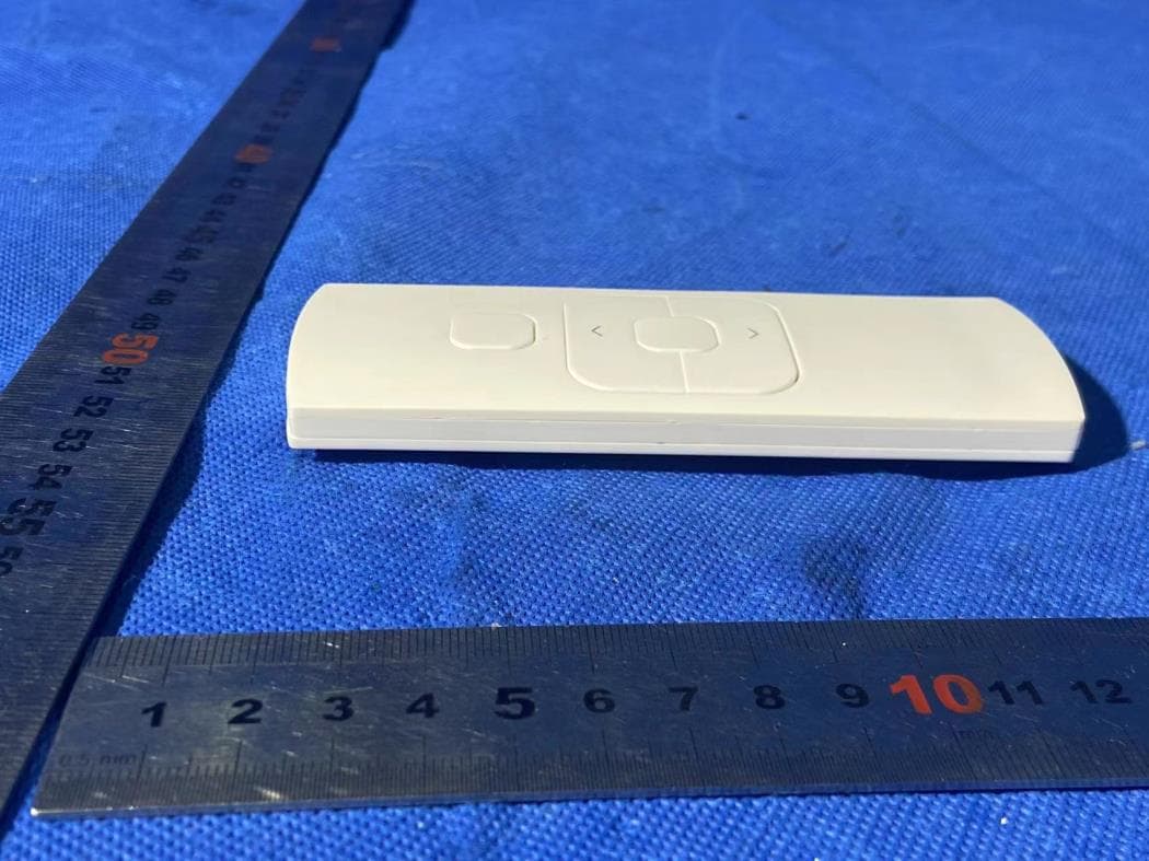
ZY4CM48
Sep 24, 2024hand-held remote with 5 channels for operating and programming blinds
Equipment Class
DSC - Part 15 Security/Remote Control Transmitter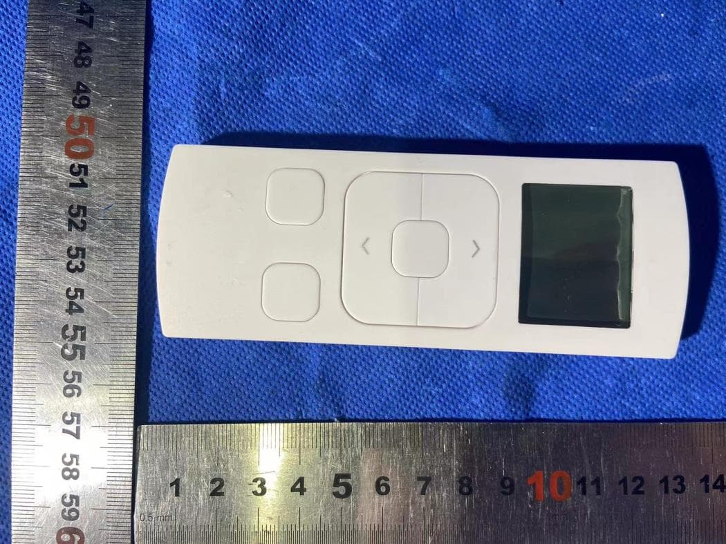
ZY4CM49
Sep 12, 2024Transmitter
Equipment Class
DSC - Part 15 Security/Remote Control Transmitter
ZY4CM36B
May 18, 2023DC CURTAIN MOTOR
Equipment Class
DTS - Digital Transmission System
ZY4CM08E
Apr 01, 2023Honeycomb Motor
Equipment Class
DTS - Digital Transmission System