ZY4CM34Receiver
Coulisse B.V.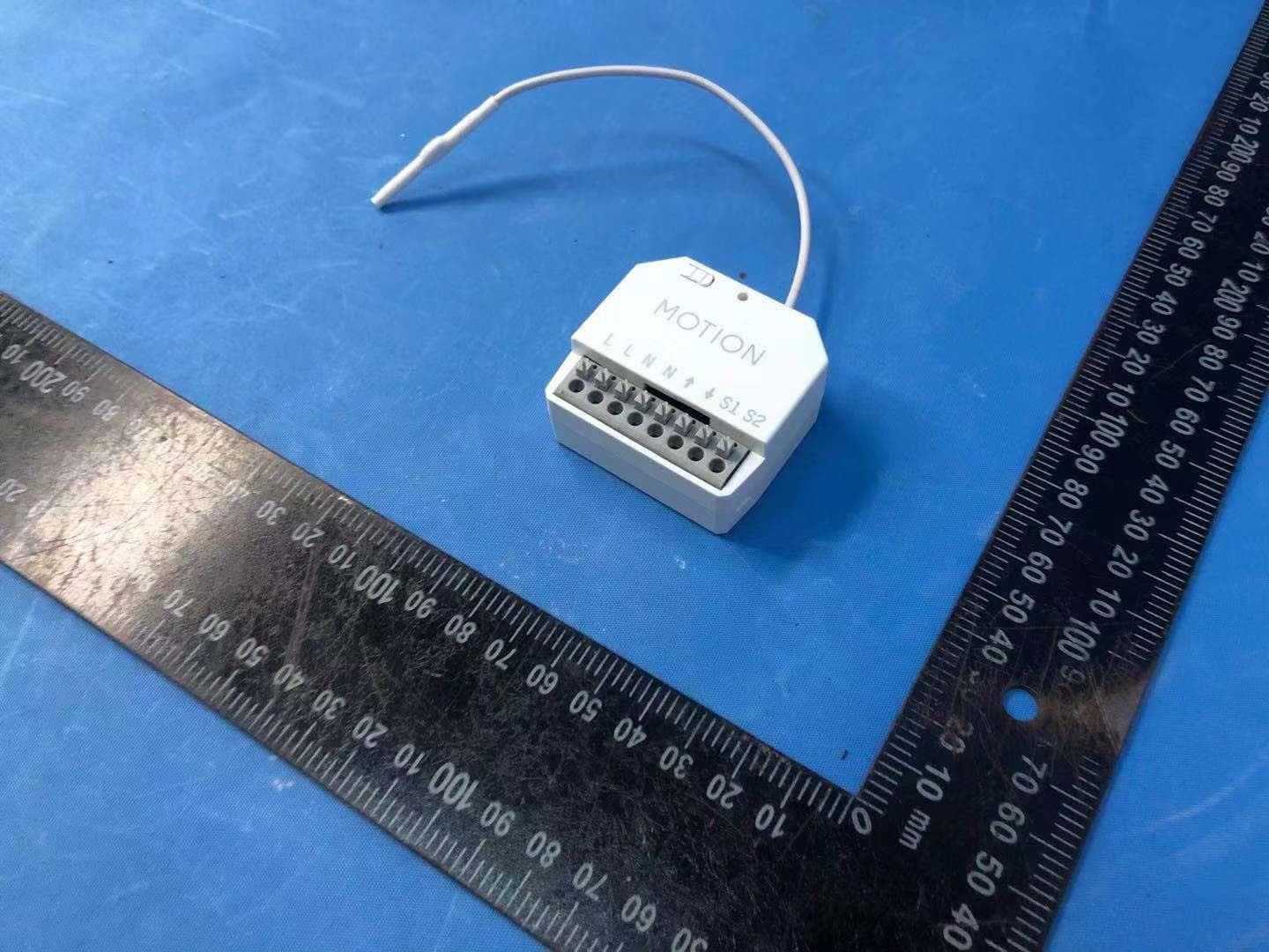
Click to zoom
Application Details
- Equipment Class
- DXT - Part 15 Low Power Transceiver, Rx Verified
- Date of Grant
- Apr 22, 2021
- Application Purpose
- Original Equipment
- Date of Application
- Apr 21, 2021
- Equipment Note
- Receiver
- Frequency Range
- 433.90000000 - 433.90000000
- Company
- Coulisse B.V.
- Country
- Netherlands
Documents & Files
Document Text
Text extracted from the exhibit documents filed with the FCC. Open a document above to read the original.
Users Manual
MANUAL CM-34-120 Smart switch wired motor English Conforms to UL Std. 325 Certified to CSA Std. C22.2#247 Smart switch wired motor CM-34 is intended to be mounted into a standard in-wall console, behind power sockets and light switches in order to control wired motors. For the latest information and updated manuals, visit rtube.nl/cm-34 Motor features Bi-directional Two-way communication for real-time response AC Motor Alternating current motor 230V Powered by 230V mains electricity Control optionsSupport Remote Control Operate with a remote controls App Control Operate with the MOTION app Connectivity Compatible with home and building automation Video How to install, program and operate rtube.nl/red1441 2 Conforms to UL Std. 325 Certified to CSA Std. C22.2#247 Safety WARNING: Important safety instructions. Follow all instructions, since incorrect installation can lead to severe injury. Do not let children play with the blind and/or remote control. Take care that the blind can move freely and is not blocked by any objects. Do not paint the device. Keep the device dry. Do not drop, knock, or shake the device. Rough handling can break internal circuit boards. Service & Support Do not perform repairs yourself. Do not attempt to open the device or disassemble it. You run the risk of electric shock and voiding the limited warranty. No user-serviceable parts are inside. Warranty Service First follow the advice in this manual. If the product appears to be damaged or does not function properly, go to your local dealer for instructions on how to obtain warranty service. Recycle This marking indicates that this product should not be disposed with other household wastes throughout the EU. To prevent possible harm to the environment or human health from uncontrolled waste disposal, recycle it responsibly to promote the sustainable reuse of material resources. To return your used device, please use the return and collec-tion systems or contact the retailer where the product was purchased. They can take this product for environmental safe recycling. 3 EU Declaration Hereby, Coulisse declares that the radio equipment type CM34 is in compliance whith directive 2014/53/EU. The full text of the EU dec- laration of conformity is available at the following internet address: www.my.coulisse.com 4 FCC Manual I FCC ID: ZY4CM34 Regulatory Information 1 FCC Information for User This product does not contain any user-serviceable components and is to be used with approved antennas only. Any product changes or modifications will invalidate all applicable regulatory certifications and approvals. 2 FCC Electronic Emission Notices This device complies with part 15 of the FCC Rules. Operation is subject to the following two conditions: 1. This device may not cause harmful interference 2. This device must accept any interference received, including interference that may cause undesired operation. 3 FCC Radio Frequency Interference Statement This equipment has been tested and found to comply with the limits for a class B digital device, pursuant to Part 15 of the FCC Rules. These limits are designed to provide reasonable protection against harmful interference when the equipment is operated in a commercial environment. This equipment generates, uses and can radiate radio-frequency energy and, if not installed and 5 used in accordance with the instructions, may cause harmful interference to radio communications. Operation of this equipment in a residential area may cause harmful interference, in which case the user will be required to correct the interference at their own expense. If this equipment does cause harmful interference to radio or television reception, which can be determined by turning the equipment off and on, the user is encouraged to try to correct the interference by one or more of the following measures: Reorient or relocate the receiving antenna Increase the distance separating the equipment and receiver Connect the equipment to an outlet on a circuit different from that to which the receiver is connected Consult the dealer or an experienced radio/TV technician for help 6 To satisfy FCC RF exposure requirements, a separation distance of 20 cm or more should be maintained between the antenna of this device and persons during device operation.To ensure compliance, operations at closer than this distance is not recommended. 7 CAUTION! Danger of electrocution. The mounting/installation of the smart switch should be done by a qualified person (electrician). CAUTION! Danger of electrocution. Even when the smart switch is turned off, it is possible there is voltage across its clamps. Every change in the connection of the clamps has to be done after ensuring all local power is powered off/disconnected. CAUTION! Do not connect the Device to appliances exceeding the given max load! CAUTION! Connect the Device only in the way shown in these instructions. Any other method could cause damage and/or injury. CAUTION! Before beginning the installation please read the accompanying documentation carefully and completely. Failure to follow recommended procedures could lead to malfunction, danger to your life or violation of the law. CAUTION! Use the Device only with power grid and appliances which comply with all applicable regulations. short circuit in the power grid or any appliance connected to the Device may damage the Device. CAUTION! Do not wire two or more motors to the smart switch. Live line for external switch 8 49mm 45mm 24mm LLNNS1S2 49mm 45mm 24mm LLNNS1S2 Input live line Live line for external switch Input neutral line Motor neutral line Down line of external switch Up line of external switch Motor down line Motor up line Program button LED 9 L L LNNS1S2 L N M 120 V 60 Hz Max. 10mm 1 Mains Cable CM-09/CM-10 230V Neutral Blue Direction 1 Brown Direction 2 Black Ground Green L = Input live line L = Live line for external switch N = Input neutral line N = Motor neutral line ↑ = Motor up line ↓ = Motor down line …
Text truncated - open the document above for the full version.
Cover Letter(s)
Coulisse B.V. Authority to Act as Agent Date: April 20, 2021 American Certification Body, Inc. 6731 Whittier Avenue Suite C110 McLean, VA 22101 To Whom It May Concern: Intertek Testing Services Shanghai is authorized to act on our behalf, until otherwise notified, for applications to American Certification Body, Inc. (ACB). We certify that we are not subject to denial of federal benefits, that includes FCC benefits, pursuant to Section 5301 of the Anti-Drug Abuse Act of 1988, 21 U.S.C. 862. Further, no party, as defined in 47 CFR 1.2002 (b), to the application is subject to denial of federal benefits, that includes FCC benefits. We also declare that the information provided to the FCC is true and correct to the best of our knowledge (47 CFR 2.911(d)) and we have been informed of the grantee responsibilities (47 CFR 2.909) with regard to certified equipment. Thank you, Agency Agreement Expiration Date: March 4, 2022 By: __________________________ _____Bas Klein Tuente______ (Signature 1 ) (Print name) Title: __Manager Engineering______ On behalf of: ____Coulisse B.V.________ (Company Name) Telephone: ____+31 547855555_______ 1 - Must be signed by applicant contact given for applicant on the FCC site, or by the authorized agent if an appropriate authorized agent letter has been provided. Letters should be placed on appropriate letterhead.
Cover Letter(s)
Coulisse B.V. Request for Confidentiality Date: April 20, 2021 Subject: Confidentiality Request for: FCC ID: ZY4CM34 Pursuant to FCC 47 CFR 0.457(d) and 0.459, the applicant requests that a part of the subject FCC application be held confidential. Type of Confidentiality Requested Exhibit ☐ Short Term ☒ Permanent Block Diagrams ☐ Short Term External Photos ☐ Short Term ☐ Permanent * 1 Internal Photos ☐ Short Term ☒ Permanent Operation Description/Theory of Operation ☐ Short Term ☐ Permanent Parts List & Placement/BOM ☐ Short Term ☐ Permanent Tune-Up Procedure ☐ Short Term ☒ Permanent Schematics ☐ Short Term Test Setup Photos ☐ Short Term ☐ Permanent * 3 User’s Manual Coulisse B.V. has spent substantial effort in developing this product and it is one of the first of its kind in industry. Having the subject information easily available to "competition" would negate the advantage they have achieved by developing this product. Not protecting the details of the design will result in financial hardship. Permanent Confidentiality: The applicant requests the exhibits listed above as permanently confidential be permanently withheld from public review due to materials that contain trade secrets and proprietary information not customarily released to the public. Short-Term Confidentiality: The applicant requests the exhibits selected above as short term confidential be withheld from public view for a period of ___(specify number of days not to exceed 180) 2 ___ days from the date of the Grant of Equipment Authorization and prior to marketing. This is to avoid premature release of sensitive information prior to marketing or release of the product to the public. Applicant is also aware that they are responsible to notify ACB in the event information regarding the product or the product is made available to the public before the requested period has expired. ACB will then release the documents listed above for public disclosure pursuant to FCC Public Notice DA 04-1705. NOTE for Industry Canada Applications: IC currently only distinguishes Permanent Confidentiality exhibits as shown above. Short Term confidentiality is not considered applicable to IC applications. Sincerely, By: __________________________ ______Bas Klein Tuente_______________ (Signature/Title 3 ) (Print name) 1 - The asterisked items (*) require further information to be provided to ACB before permanent confidentiality will be extended to these exhibits. Please refer to FCC KDB 726920 and the specific Document link for D01 found at: https://apps.fcc.gov/oetcf/kdb/forms/FTSSearchResultPage.cfm?switch=P&id=41731 and review section II, 3) regarding specific information that must accompany these requests. 2 - Please refer to http://acbcert.com/documents/misc-docs/Memo-Short-Term-Vs-Standard-Confidentiality.pdf for complete details. 3 - Must be signed by applicant contact given for applicant on the FCC site, or by the authorized agent if an appropriate authorized agent letter has been provided. Letters should be placed on appropriate letterhead.
External Photos
FCC ID: ZY4CM34 Page 1 of 3 External Picture FCC ID: ZY4CM34 Page 2 of 3 FCC ID: ZY4CM34 Page 3 of 3
ID Label/Location Info
Label Location
Internal Photos
FCC ID: ZY4CM34 Page 1 of 3 Internal Picture FCC ID: ZY4CM34 Page 2 of 3 FCC ID: ZY4CM34 Page 3 of 3
RF Exposure Info
Coulisse B.V. MPE ASSESSMENT REPORT Report Type: FCC MPE assessment report Model: CM-34-120 REPORT NUMBER: 201101037SHA-002 ISSUE DATE: March 5, 2021 DOCUMENT CONTROL NUMBER: TTRFFCCMPE-01_V1 © 2018 Intertek Intertek Testing Services Shanghai Building No.86, 1198 Qinzhou Road (North) Caohejing Development Zone Shanghai 200233, China Telephone: 86 21 6127 8200 www.intertek.com TEST REPORT This report is for the exclusive use of Intertek's Client and is provided pursuant to the agreement between Intertek and its Client. Intertek's responsibility and liability are limited to the terms and conditions of the agreement. Intertek assumes no liability to any party, other than to the Client in accordance with the agreement, for any loss, expense or damage occasioned by the use of this report. Only the Client is authorized to permit copying or distribution of this report and then only in its entirety. Any use of the Intertek name or one of its marks for the sale or advertisement of the tested material, product or service must first be approved in writing by Intertek. The observations and test results in this report are relevant only to the sample tested. This report by itself does not imply that the material, product, or service is or has ever been under an Intertek certification program. TTRFFCCMPE-01_V1© 2018 Intertek Page 2 of 8 Report no.: 201101037SHA-002 Applicant: Coulisse B.V. VONDERWEG 48, 7568 DC ENTER, NETHERLANDS Manufacturer: Coulisse B.V. VONDERWEG 48, 7568 DC ENTER, NETHERLANDS FCC ID: ZY4CM34 SUMMARY: The equipment complies with the requirements according to the following standard(s) or Specification: KDB447498 D01 General RF Exposure Guidance v06 FCC Part2.1091, FCC Part2.1093 FCC Part1.1307(b) PREPARED BY: REVIEWED BY: Project Engineer Erick Liu Reviewer Daniel Zhao Report No.: 201101037SHA-002 TEST REPORT TTRFFCCMPE-01_V1© 2018 Intertek Page 3 of 8 Revision History Report No. Version Description Issued Date 201101037SHA-002 Rev. 01 Initial issue of report March 5, 2021 Report No.: 201101037SHA-002 TEST REPORT TTRFFCCMPE-01_V1© 2018 Intertek Page 4 of 8 1 GENERAL INFORMATION 1.1 Description of Equipment Under Test (EUT) Product name: Receiver Type/Model: CM-34-120 Description of EUT: The EUT is a transceiver, it works at 433.90MHz Frequency, there is only one model, we test it and list the worst results in this report. Rating: Input: 120Vac, 60Hz, 3A; Output: max.360W, 3A Category of EUT: Class B EUT type: Table top Floor standing Software Version: / Hardware Version: / Sample received date: November 23, 2020 Date of test: December 02, 2020 – January 28, 2021 1.2 Technical Specification Operation Frequency: 433.90MHz Type of Modulation: GFSK Product Type: Mobile Portable Fix Location Channel Number: 1 Antenna Designation: Line Antenna Gain of Antenna: 2.5dBi Report No.: 201101037SHA-002 TEST REPORT TTRFFCCMPE-01_V1© 2018 Intertek Page 5 of 8 1.3 Description of Test Facility Name: Intertek Testing Services Shanghai Address: Building 86, No. 1198 Qinzhou Road(North), Shanghai 200233, P.R. China Telephone: 86 21 61278200 Telefax: 86 21 54262353 The test facility is recognized, certified, or accredited by these organizations: CNAS Accreditation Lab Registration No. CNAS L0139 FCC Accredited Lab Designation Number: CN1175 IC Registration Lab CAB identifier.: CN0051 VCCI Registration Lab Registration No.: R-14243, G-10845, C-14723, T-12252 A2LA Accreditation Lab Certificate Number: 3309.02 Report No.: 201101037SHA-002 TEST REPORT TTRFFCCMPE-01_V1© 2018 Intertek Page 6 of 8 2 MPE Assessment Test result: Pass 2.1 MPE Assessment Limit Mobile device exposure for standalone operations: Frequency range E-field strength (V/m) H-field strength (A/m) B-field (uT) Equivalent plane wave power density S eq (W/m 2 ) 0-1 Hz - 3,2 × 10 4 4 × 10 4 - 1-8 Hz 10 000 3,2 × 10 4 /f 2 4 × 10 4 /f 2 - 8-25 Hz 10 000 4 000/f 5 000/f - 0,025-0,8 kHz 250/f 4/f 5/f - 0,8-3 kHz 250/f 5 6,25 - 3-150 kHz 87 5 6,25 - 0,15-1 MHz 87 0,73/f 0,92/f - 1-10 MHz 87/f 1/2 0,73/f 0,92/f - 10-400 MHz 28 0,073 0,092 2 400-2 000 MHz 1,375 f 1/2 0,0037 f 1/2 0,0046 f 1/2 f/200 2-300 GHz 61 0,16 0,20 10 Mobile device exposure for simultaneous transmission operations: the sum of the MPE ratios for all simultaneously transmitting antennas incorporated in a host device is ≤ 1.0 Report No.: 201101037SHA-002 TEST REPORT TTRFFCCMPE-01_V1© 2018 Intertek Page 7 of 8 2.2 Assessment Results Power density (S) is calculated according to the formula: S = P / (4πR²) Where S = power density in mW/cm² P = Radiated transmit power in mW G = numeric gain of transmit antenna R = distance (cm) As we can see from the test report 201101037SHA-001: The maximum radiated power = 80.80-95.3= -14.5dBm =0.04 mW; Here R is chosen to be 20cm, S = P / (4πR²) = 0.04 / (4 * 3.14 * 20 * 20) = 0.000007 mW/cm² < 1 mW/cm² Report No.: 201101037SHA-002 TEST REPORT TTRFFCCMPE-01_V1© 2018 Intertek Page 8 of 8 Appendix I Definition below must be outlined in the User Manual: To satisfy FCC RF exposure requirements, a separation distance of 20 cm or more should be maintained between the antenna of this device and persons during device operation. To ensure compliance, operations at closer than this distance is not recommended. ******************************************* END ************************************
Test Report
cCoulisse B.V. RF TEST REPORT Report Type: FCC Part 15.231 RF report Model: CM-34-120 REPORT NUMBER: 201101037SHA-001 ISSUE DATE: March 5, 2021 DOCUMENT CONTROL NUMBER: TTRF15.231_V1 © 2018 Intertek Intertek Testing Services Shanghai Building No.86, 1198 Qinzhou Road (North) Caohejing Development Zone Shanghai 200233, China Telephone: 86 21 6127 8200 www.intertek.com TEST REPORT This report is for the exclusive use of Intertek's Client and is provided pursuant to the agreement between Intertek and its Client. Intertek's responsibility and liability are limited to the terms and conditions of the agreement. Intertek assumes no liability to any party, other than to the Client in accordance with the agreement, for any loss, expense or damage occasioned by the use of this report. Only the Client is authorized to permit copying or distribution of this report and then only in its entirety. Any use of the Intertek name or one of its marks for the sale or advertisement of the tested material, product or service must first be approved in writing by Intertek. The observations and test results in this report are relevant only to the sample tested. This report by itself does not imply that the material, product, or service is or has ever been under an Intertek certification program. TTRF15.231_V1 © 2018 Intertek Page 2 of 29 Report no.: 201101037SHA-001 Applicant: Coulisse B.V. VONDERWEG 48, 7568 DC ENTER, NETHERLANDS Manufacturer: Coulisse B.V. VONDERWEG 48, 7568 DC ENTER, NETHERLANDS FCC ID: ZY4CM34 SUMMARY: The equipment complies with the requirements according to the following standard(s) or Specification: 47CFR Part 15 (2019): Radio Frequency Devices (Subpart C) ANSI C63.10 (2013): American National Standard of Procedures for Compliance Testing of Unlicensed Wireless Devices PREPARED BY: REVIEWED BY: Project Engineer Erick Liu Reviewer Daniel Zhao Report No.: 201101037SHA-001 TEST REPORT TTRF15.231_V1 © 2018 Intertek Page 3 of 29 Content REVISION HISTORY................................................................................................................................................ 4 MEASUREMENT RESULT SUMMARY ..................................................................................................................... 5 1 GENERAL INFORMATION ............................................................................................................................. 6 1.1 DESCRIPTION OF EQUIPMENT UNDER TEST (EUT) ..................................................................................................... 6 1.2 TECHNICAL SPECIFICATION .................................................................................................................................... 6 1.3 DESCRIPTION OF TEST FACILITY .............................................................................................................................. 7 2 TEST SPECIFICATIONS ................................................................................................................................... 8 2.1 STANDARDS OR SPECIFICATION ............................................................................................................................... 8 2.2 MODE OF OPERATION DURING THE TEST ................................................................................................................... 8 2.3 TEST SOFTWARE LIST ............................................................................................................................................ 8 2.4 TEST PERIPHERALS LIST ......................................................................................................................................... 8 2.5 TEST ENVIRONMENT CONDITION: ............................................................................................................................ 9 2.6 INSTRUMENT LIST .............................................................................................................................................. 10 2.7 MEASUREMENT UNCERTAINTY ............................................................................................................................. 12 3 FUNDAMENTAL & SPURIOUS EMISSION & RESTRICT BAND RADIATED EMISSION ...................................... 13 3.1 LIMIT .............................................................................................................................................................. 13 3.2 MEASUREMENT PROCEDURE ............................................................................................................................... 14 3.3 TEST CONFIGURATION ........................................................................................................................................ 15 3.4 TEST RESULTS OF RADIATED EMISSIONS ................................................................................................................. 17 4 POWER LINE CONDUCTED EMISSION ......................................................................................................... 20 4.1 LIMIT .............................................................................................................................................................. 20 4.2 TEST CONFIGURATION ........................................................................................................................................ 20 4.3 MEASUREMENT PROCEDURE ............................................................................................................................... 21 4.4 TEST RESULTS OF POWER LINE CONDUCTED EMISSION............................................................................................... 22 5 EMISSION BANDWIDTH ............................................................................................................................. 24 5.1 TEST CONFIGURATION ......................................................................................................…
Text truncated - open the document above for the full version.
Test Setup Photos
FCC ID: ZY4CM34 Page 1 of 3 Test Setup FCC ID: ZY4CM34 Page 2 of 3 Conducted Emission FCC ID: ZY4CM34 Page 3 of 3 Radiated Emission
Contact Information
Applicant
Bas Klein Tuente(Manager Engineering)
Technical Contact
Intertek Testing Services ShanghaiErick Liu
[email protected]86 21 61215117
Building No.86, 1198 Qinzhou Road(North) · Shanghai · China
Test Firm
Intertek Testing Services ShanghaiLeah Xu
[email protected]+86 21 61278200
Technical Specifications
| # | Rule Parts | Frequency Range | Power Output |
|---|---|---|---|
| 1 | 15C | 433.9 MHz - 433.9 MHz | - |
Other Applications from Coulisse B.V.
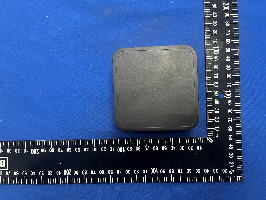
ZY4CM55
Sep 26, 2024Motionblinds Wifi Matter Bridge
Equipment Class
DSS - Part 15 Spread Spectrum Transmitter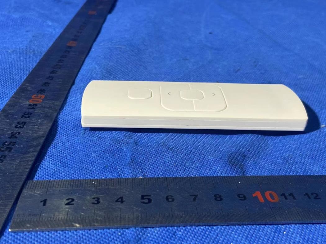
ZY4CM48
Sep 24, 2024hand-held remote with 5 channels for operating and programming blinds
Equipment Class
DSC - Part 15 Security/Remote Control Transmitter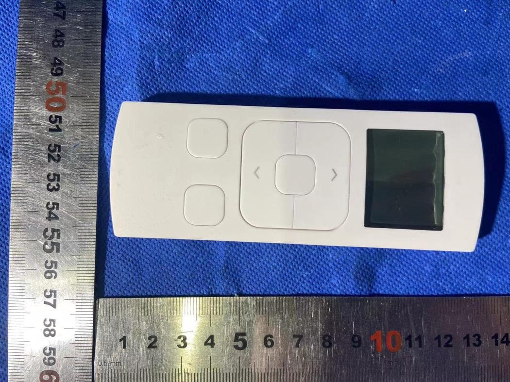
ZY4CM49
Sep 12, 2024Transmitter
Equipment Class
DSC - Part 15 Security/Remote Control Transmitter
ZY4CM36B
May 18, 2023DC CURTAIN MOTOR
Equipment Class
DTS - Digital Transmission System
ZY4CM08E
Apr 01, 2023Honeycomb Motor
Equipment Class
DTS - Digital Transmission System