2AB6O7470Paging transmitter
Long Range Solutions, LLC
Click to zoom
Application Details
- Equipment Class
- TNB - Licensed Non-Broadcast Station Transmitter
- Date of Grant
- Apr 28, 2014
- Application Purpose
- Original Equipment
- Date of Application
- Apr 28, 2014
- Equipment Note
- Paging transmitter
- Frequency Range
- 467.75000000 - 467.75000000
- Company
- Long Range Solutions, LLC
- Country
- United States
Documents & Files
Document Text
Text extracted from the exhibit documents filed with the FCC. Open a document above to read the original.
Users Manual
Long Range Systems, LLC 4550 Excel Parkway, Suite 200 Addison, TX 75001 800.437.4996 • 214.553.5308 www.pager.net (T7470 Paging System Transmitter) USER MANUAL Table Of Contents Compatible Pagers . . . . . . . . . . . . . . . . . . . . . . . . . . . . . . . . . . . . . . . . . . . . . . . . . . . . . . . . . . . . 3 Installation and Setup . . . . . . . . . . . . . . . . . . . . . . . . . . . . . . . . . . . . . . . . . . . . . . . . . . . . . . . . . 4 Hardware Provided . . . . . . . . . . . . . . . . . . . . . . . . . . . . . . . . . . . . . . . . . . . . . . . . . . .4 I nstallation Procedure . . . . . . . . . . . . . . . . . . . . . . . . . . . . . . . . . . . . . . . . . . . . . . . . .4 Connections . . . . . . . . . . . . . . . . . . . . . . . . . . . . . . . . . . . . . . . . . . . . . . . . . . . . . . . . .4 Keypad Description . . . . . . . . . . . . . . . . . . . . . . . . . . . . . . . . . . . . . . . . . . . . . . . . . . .5 Initial Power Up and Time Set . . . . . . . . . . . . . . . . . . . . . . . . . . . . . . . . . . . . . . . . . .5 Basic Paging Operation Guide . . . . . . . . . . . . . . . . . . . . . . . . . . . . . . . . . . . . . . . . . . . . . . . . . . 6 Page Guest Pagers . . . . . . . . . . . . . . . . . . . . . . . . . . . . . . . . . . . . . . . . . . . . . . . . . . . .6 Page Individual Staff Pagers . . . . . . . . . . . . . . . . . . . . . . . . . . . . . . . . . . . . . . . . . . . .6 Page a Cell Phone . . . . . . . . . . . . . . . . . . . . . . . . . . . . . . . . . . . . . . . . . . . . . . . . . . . .7 Canned or Special Alphanumeric Messages . . . . . . . . . . . . . . . . . . . . . . . . . . . . . .7 Canned Message . . . . . . . . . . . . . . . . . . . . . . . . . . . . . . . . . . . . . . . . . . . . . . . . . . . .8 Special Functions . . . . . . . . . . . . . . . . . . . . . . . . . . . . . . . . . . . . . . . . . . . . . . . . . . . . . . . . . . . . . 9 Theft-Deterrent Function . . . . . . . . . . . . . . . . . . . . . . . . . . . . . . . . . . . . . . . . . . . . . . .9 Tracking . . . . . . . . . . . . . . . . . . . . . . . . . . . . . . . . . . . . . . . . . . . . . . . . . . . . . . . . . . . . .10 Custom Tracking . . . . . . . . . . . . . . . . . . . . . . . . . . . . . . . . . . . . . . . . . . . . . . . . . . . . .10 Group Paging . . . . . . . . . . . . . . . . . . . . . . . . . . . . . . . . . . . . . . . . . . . . . . . . . . . . . . . .11 Manager Mapping . . . . . . . . . . . . . . . . . . . . . . . . . . . . . . . . . . . . . . . . . . . . . . . . . . . .12 Dry Contact . . . . . . . . . . . . . . . . . . . . . . . . . . . . . . . . . . . . . . . . . . . . . . . . . . . . . . . . .12 Set Alarms . . . . . . . . . . . . . . . . . . . . . . . . . . . . . . . . . . . . . . . . . . . . . . . . . . . . . . . . . .13 Feature Setup Procedures . . . . . . . . . . . . . . . . . . . . . . . . . . . . . . . . . . . . . . . . . . . . . . . . . . . . . .15 User Password . . . . . . . . . . . . . . . . . . . . . . . . . . . . . . . . . . . . . . . . . . . . . . . . . . . . . . .15 Set Manager Password . . . . . . . . . . . . . . . . . . . . . . . . . . . . . . . . . . . . . . . . . . . . . . . .15 Set Page Mode . . . . . . . . . . . . . . . . . . . . . . . . . . . . . . . . . . . . . . . . . . . . . . . . . . . . . . .15 Set to Page Staff or Guest Pagers . . . . . . . . . . . . . . . . . . . . . . . . . . . . . . . . . . . . . . .16 Create Alphanumeric Messages . . . . . . . . . . . . . . . . . . . . . . . . . . . . . . . . . . . . . . . . .16 Setting System Time/Date for Freedom Transmitter (T7470) . . . . . . . . . . . . . . . . . .17 Repeat Delay . . . . . . . . . . . . . . . . . . . . . . . . . . . . . . . . . . . . . . . . . . . . . . . . . . . . . . . . .18 ID Span . . . . . . . . . . . . . . . . . . . . . . . . . . . . . . . . . . . . . . . . . . . . . . . . . . . . . . . . . . . . .18 Alphanumeric Pager Button Enable/Disable . . . . . . . . . . . . . . . . . . . . . . . . . . . . . .18 Guest Message . . . . . . . . . . . . . . . . . . . . . . . . . . . . . . . . . . . . . . . . . . . . . . . . . . . . . .18 Freeform Messages . . . . . . . . . . . . . . . . . . . . . . . . . . . . . . . . . . . . . . . . . . . . . . . . . . .19 Alpha Vibration Level . . . . . . . . . . . . . . . . . . . . . . . . . . . . . . . . . . . . . . . . . . . . . . . . .19 Display the Prompt . . . . . . . . . . . . . . . . . . . . . . . . . . . . . . . . . . . . . . . . . . . . . . . . . . .19 Turning ON/OFF Canned Messages in Display Prompt . . . . . . . . . . . . . . . . . . . . . .20 Editing Canned Messages in Display Prompt . . . . . . . . . . . . . . . . . . . . . . . . . . . . .20 Freeform Staff Message . . . . . . . . . . . . . . . . . . . . . . . . . . . . . . . . . . . . . . . . . . . . . . .20 Long Range Systems1Freedom User Manual Display the Staff Prompt . . . . . . . . . . . . . . . . . . . . . . . . . . . . . . . . . . . . . . . . . . . . . . .21 Staff Message . . . . . . . . . . . . . . . . . . . . . . . . . . . . . . . . . . . . . . . . . . . . . . . . . . . . . . . .21 Turning ON/OFF Canned Messages in Staff Display Prompt . . . . . . . . . . . . . . . . .21 E diting Canned Messages in Staff Display Prompt . . . . . . . . . . . . . . . . . . . . . . . . .22 USB Keyboard . . . . . . . . . . . . . . . . . . . . . . . . . . . . . . . . . . . . . . . . . . . . . . . . . . . . . . .22 Alpha Pager Communication Baud Rate . . . . . . . . . . . . . . . . . . . . . . . . . . . . . . . . . .22 Maintenance Functions . . . . . . . . . . . . . . . . . . . . . . . . . . . . . . . . . . . . . . . . . . . . . . . . . . . . . . . .23 Paging Types in Mixed Systems . . . . . . . . . . . . . . . . . . . . . . . . . . . . . . . . . . . . . . . . .23 Station ID . . . . . . . . . . . . . . . . . . . . . . . . . . . . . . . . . . . . . . . . . . . . . . . . . . . . . . . . . . .23 Adjust Transmit Power . . . . . . . . . . . . . . . . . . . . . . . . . . . . . . . . . . . . . . . . .…
Text truncated - open the document above for the full version.
Users Manual
Installation, Warranty and Service Information Long Range Systems, LLC 4550 Excel Parkway, Suite 200 Addison, TX 75001 800.437.4996 • www.pager.net T 7 4 7 0 C 2 3 2 F C C I D : M 7 4 T 7 4 0 0 R S - 2 3 2 R e c e i v e T r a n s m i t P o w e r 1 2 V D C 8 0 0 . 4 3 7 . 4 9 9 6 w w w . p a g e r . n e t CONDOR C L A S S 2 T R A N S F O R M E R ( 4 0 8 ) 7 4 5 - 7 1 4 1 I N P U T : A C 1 2 O V 6 0 H z 1 9 w O U T P U T : A C 9 V 1 8 0 0 m A P / N : A 9 1 A 8 R o H S U U L L L ISTED C M O D E L : 4 8 A - 9 - 1 8 0 0 E I A 3 6 3 0 6 3 5 S M A D E I N C H I N A TX-7470-C232 Paging System Transmitter USER MANUAL Table Of Contents Installation and Setup . . . . . . . . . . . . . . . . . . . . . . . . . . . . . . . . . . . . . . . . . . . . 2 Set Restaurant ID . . . . . . . . . . . . . . . . . . . . . . . . . . . . . . . . . . . . . . . . . . . . . . . . . . . . . 3 Repeat Delay . . . . . . . . . . . . . . . . . . . . . . . . . . . . . . . . . . . . . . . . . . . . . . . . . . . . . . . . . 4 High Power Setting . . . . . . . . . . . . . . . . . . . . . . . . . . . . . . . . . . . . . . . . . . . . . . . . . . . 4 Frequency . . . . . . . . . . . . . . . . . . . . . . . . . . . . . . . . . . . . . . . . . . . . . . . . . . . . . . . . . . . 5 Service Questions and Answers . . . . . . . . . . . . . . . . . . . . . . . . . . . . . . . . . . . . . 6 Warranty . . . . . . . . . . . . . . . . . . . . . . . . . . . . . . . . . . . . . . . . . . . . . . . . . . . . . . . 7 Long Range Systems1TX-7470-C232 User Manual INSTALLATION AND SETUP Basic Installation 1) Plug the 12V power supply into the side of the Transmitter. 2) Connect the serial cable from the connector on the Transmitter to the serial port on the host com- puter. 3) Note the COM Port that the serial cable is connected to on the host computer. 4) Open HyperTerminal on the host computer. 5) Assign a Name for the new connection. 6) Select the COM Port coming from the serial cable. 7) Use the following settings: Bits per second: 9600 Data bits:8 Parity:None Stop bits:1 Flow control:None 8) Type ECHO1 and press ENTER. (This echo function will allow you to see what is being typed.) 9) You are now ready to use the interface. Note:At any time, use the STAT command to view any changes. Long Range Systems2TX-7470-C232 User Manual Screen View of ECHO ON Screen View of Typing ECHO Set Restaurant ID This must be set correctly to page pagers. T o set the Restaurant ID, type RID,x and press ENTER twice. X is the Restaurant ID. Example:To set an ID of 2, type RID,2 and press ENTER twice. Long Range Systems3TX-7470-C232 User Manual Example Restaurant ID to 2 HyperTerminal Output Showing ID as 2 Type STAT and press ENTER Status View Showing Restaurant ID as 2 Repeat Delay To turn ON Repeat Delay, type RPTDLY,1 and press ENTER twice. To turn OFF Repeat Delay, type RPTDLY,0 and press ENTER twice. High Power Setting To change the Power Setting, type HWPR,x and press ENTER twice. X is the Power Setting, a value of 0 to 4. Example: To set a Power Setting of 3, type HWPR,3 and press ENTER twice.. Long Range Systems4TX-7470-C232 User Manual Example Repeat Delay ON Status View Showing Repeat Delay ON Example High Power Set to 1 HyperTerminal Output Showing High Power Set to 1 Status View Showing High Power Set to 1 Long Range Systems5TX-7470-C232 User Manual SERVICE QUESTIONS AND ANSWERS Should your paging system ever fail or should you need additional paging supplies, call Long Range Systems at (800) 437-4996 Monday through Friday 8:30 am to 5:00 pm Central Time. F or weekend or night emergencies: • Long Range Systems has 24/7 live technical support available • Please keep in mind that options are limited over the weekend. FCC STATEMENT 1. This device complies with Part 15 of the FCC Rules. Operation is subject to the following two conditions: (1) This device may not cause harmful interference. (2) This device must accept any interference received, including interference that may cause unde- sired operation. 2. Changes or modifications not expressly approved by the party responsible for compliance could void the user's authority to operate the equipment. NOTE:This equipment has been tested and found to comply with the limits for a Class B digital de- vice, pursuant to Part 15 of the FCC Rules. These limits are designed to provide reasonable protection against harmful interference in a residential installation. This equipment generates uses and can radiate radio frequency energy and, if not installed and used in ac- cordance with the instructions, may cause harmful interference to radio communications. However, there is no guarantee that interference will not occur in a particular installation. If this equipment does cause harm- ful interference to radio or television reception, which can be determined by turning the equipment off and on, the user is encouraged to try to correct the interference by one or more of the following measures: •Reorient or relocate the receiving antenna. •Increase the separation between the equipment and receiver. •Connect the equipment into an outlet on a circuit different from that to which the receiver is con- nected. • Consult the dealer or an experienced radio/TV technician for help. RF warning statement: The device has been evaluated to meet general RF exposure requirement. The device can be used in portable exposure condition without restriction. Warranty Long Range Systems, LLC permits a one-year manufacturer’s warranty following the original consumer purchase date of any LRS system. Any individual components or products purchased will receive a 30-day manufacture warranty. This warranty covers any defects due to faulty material or workmanship, but does not include damage to the product result- ing from accident, misuse or improper electrical connection. If the product or system should become defective within the warranty period, we will repair or replace with equivalent equipment, free of charge. We will pay transportation charges…
Text truncated - open the document above for the full version.
External Photos
15689 TX‐7470 External Photographs Page 1 of 3 Side 1 of 6: Rear with Connectors Side 2 of 6: Top 15689 TX‐7470 External Photographs Page 2 of 3 Side 3 of 6: Left Side Side 4 of 6: Bottom Side 5 of 6: Right Side 15689 TX‐7470 External Photographs Page 3 of 3 Side 6 of 6: Front ***
External Photos
15689 TX‐7470‐C232 External Photographs Page 1 of 3 Side 1 of 6: Left Side Side 2 of 6: Right Side 15689 TX‐7470‐C232 External Photographs Page 2 of 3 Side 3 of 6: Front Side Side 4 of 6: Rear Connector Side 15689 TX‐7470‐C232 External Photographs Page 3 of 3 Side 5 of 6: Bottom Side 6 of 6: Top ***
ID Label/Location Info
Long Range Systems LABEL ART AND SPECS 04-16-14 TX-T7470-C232 FCC Label Placement & Dimensions Long Range Systems, LLC FCC ID: 2AB6O7470 MODEL: TX-7470-C232 Label goes here 2.03” x 0.55”
Internal Photos
15689 TX ‐ 7470 Internal Photographs Page 1 of 3 15689 TX ‐ 7470 Internal Photographs Page 2 of 3 15689 TX ‐ 7470 Internal Photographs Page 3 of 3
Internal Photos
15689 TX ‐ 7470 Internal Photographs Page 1 of 3 15689 TX ‐ 7470 Internal Photographs Page 2 of 3 15689 TX ‐ 7470 Internal Photographs Page 3 of 3
RF Exposure Info
15689 Exposure Supplemental Report Rev01 Page 1 of 2 1.0 Exposure Exemption Evaluation The results of power measurement and intended use/proximity are compared against the requirements for safety of RF exposure. 1.2 Criteria Section Reference Date 2.1091, FCC OET Bulletin 65, KDB 447498 Section 4.3.1 2014‐04‐26 1.3 Procedure Using measurement of peak power and intended application, determine the permissible exposure level or whether additional exposure tests (SAR) are indicated. Justify conclusion for selected exposure area and separation distance. 1.4 Exemption Calculation Antenna for this device is a short quarter-wave whip antenna that attaches by right-angle BNC connector to the rear surface of the EUT. The operating frequency is 467.75 MHz. The required separation for the frequency and power is determined from KDB 447498 Section 4.3.1.2 and restated as follows: Using the above values, the distance is calculated as follows: The following page includes photographs to illustrate the measured distance from the antenna to the user hand. The measured distance is 105 mm. The EUT therefore meets the criteria for exclusion from SAR testing. KDB 447498 Clause 4.3.1.2 (but using Annex B approximations) MHz5060708090100 mm 450224254284314344374 mW 468221252284315346377 mW 835164220275331387442 mW MHz5060708090100 mm 450560635710785860935 mW 468553631709787865943mW 8354105506888289681105 mW MHz7071727374757677787980mm 468709717725732740748756764771779787mW 15689 Exposure Supplemental Report Rev01 Page 2 of 2 1.5 Photograph Antenna to Hand Distance 105 mm Measured from nearest surface of antenna, across top of enclosure and to nearest edge of nearest button (F2) in the user keypad area. ***
Test Report
1601 North A.W. Grimes Blvd., Suite B Round Rock, TX 78665 e-mail: [email protected] (512) 244-3371 Fax: (512) 244-1846 April 22, 2014 John Weber Long Range Systems, LLC 4550 Excel Parkway Suite 200 Addison TX 75001 Dear John: Thank you for allowing Professional Testing (EMI), Inc. an opportunity to perform testing for Long Range Systems, LLC. Enclosed is the Wireless Certification Report for the TX-7470 LRS Paging Transmitter. This report can be used to demonstrate compliance with FCC requirements for wireless devices in the United States. If you have any questions, please contact me. Sincerely, Jeffrey A. Lenk President Attachment Wireless Certification Report for the TX-7470 by Long Range Systems, LLC 15689-10 Page 2 of 43 Project 15689-10 TX-7470 LRS Paging Transmitter Wireless Certification Report Prepared for: Long Range Systems, LLC By Professional Testing (EMI), Inc. 1601 North A.W. Grimes Blvd., Suite B Round Rock, Texas 78665 April 22, 2014 Reviewed by Written by Larry Finn Regulatory Design Engineer Eric Lifsey Test Engineer Wireless Certification Report for the TX-7470 by Long Range Systems, LLC 15689-10 Page 3 of 43 Revision History Revision Number Description Date 00 Initial draft for review. April 22, 2014 01 Revised per Larry Finn review. April 22, 2014 Wireless Certification Report for the TX-7470 by Long Range Systems, LLC 15689-10 Page 4 of 43 Table of Contents Revision History ............................................................................................................................................................ 3 Certificate of Compliance ............................................................................................................................................. 5 1.0 Introduction.......................................................................................................................................................... 6 1.1 Scope ............................................................................................................................................................... 6 1.2 EUT Description ............................................................................................................................................. 6 1.3 EUT Operation ................................................................................................................................................ 6 1.4 Modifications to Equipment ............................................................................................................................ 7 1.5 Test Site .......................................................................................................................................................... 7 2.0 Applicable Documents and Clauses ..................................................................................................................... 8 3.0 Conducted Output Power [90.205] ...................................................................................................................... 9 3.1 Procedure ........................................................................................................................................................ 9 3.2 Criteria ............................................................................................................................................................ 9 3.3 Results ............................................................................................................................................................. 9 4.0 Emission Mask [90.210(d)(1-3)] ....................................................................................................................... 10 4.1 Procedure ...................................................................................................................................................... 10 4.2 Criteria .......................................................................................................................................................... 10 4.3 Results ........................................................................................................................................................... 10 5.0 Spurious Emissions at Antenna Terminals [90.210(e)(3)] ................................................................................. 11 5.1 Procedure ...................................................................................................................................................... 11 5.2 Criteria .......................................................................................................................................................... 11 5.3 Results ........................................................................................................................................................... 11 6.0 Field Strength of Radiated Unintentional Emissions – Receive Mode [15.109] ............................................... 14 6.1 Procedure ...................................................................................................................................................... 14 6.2 Criteria .......................................................................................................................................................... 14 6.3 Results ........................................................................................................................................................... 14 7.0 Field Strength of Radiated Spurious Emissions – Transmit Mode [90.210(d)] ................................................. 21 7.1 Procedure ...................................................................................................................................................... 21 7.2 Criteria ....................................................................................................................................................…
Text truncated - open the document above for the full version.
Test Setup Photos
15689 Test Setup Photographs Page 1 of 4 Conducted: Fundamental Power, Spurious, Bandwidth Transmit Transient Frequency Stability – Temperatures, 1 of 2 15689 Test Setup Photographs Page 2 of 4 Frequency Stability ‐ Temperatures, 2 of 2 Frequency Stability, Mains Power (EUT in temperature chamber.) Radiated Emissions, Receive Mode, Front View 15689 Test Setup Photographs Page 3 of 4 Radiated Emissions, Receive Mode, Rear View Radiated Emissions, Receive Mode, Support Equipment in Subfloor Chamber Radiated Emissions, Transmit Mode, Front View 15689 Test Setup Photographs Page 4 of 4 Radiated Emissions, Transmit Mode, Rear View Radiated Emissions, Transmit Mode, EUT Display with Scrolling Data ***
Contact Information
Applicant
Robert Pinell(Chief Officer)
Test Firm
Professional Testing (EMI), Inc.Larry Finn
Technical Specifications
| # | Rule Parts | Frequency Range | Power Output | Emission | Tolerance |
|---|---|---|---|---|---|
| 1 | 90 | 467.75 MHz - 467.75 MHz | 757.00 mW | 8K60G1D | 1.7700000000 ppm |
Other Applications from Long Range Solutions, LLC
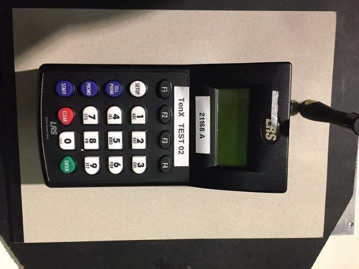
2AB6OTX7471
Mar 11, 2020Paging transmitter
Equipment Class
TNB - Licensed Non-Broadcast Station Transmitter
2AB6OTX7470
Apr 28, 2015Paging Transmitter for restaurant seating
Equipment Class
TNB - Licensed Non-Broadcast Station Transmitter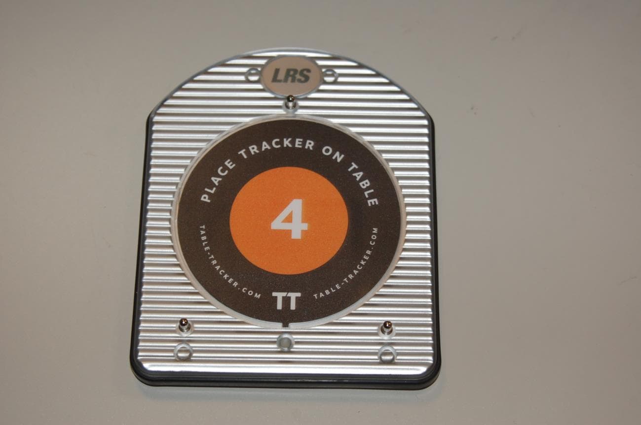
2AB6OTRACKER
Feb 23, 2015Table-Tracking Paging Receiver
Equipment Class
DXX - Part 15 Low Power Communication Device Transmitter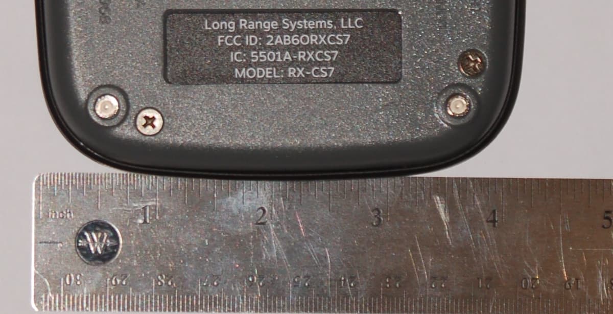
2AB6ORXCS7
Feb 12, 2015Paging Receiver
Equipment Class
DSC - Part 15 Security/Remote Control Transmitter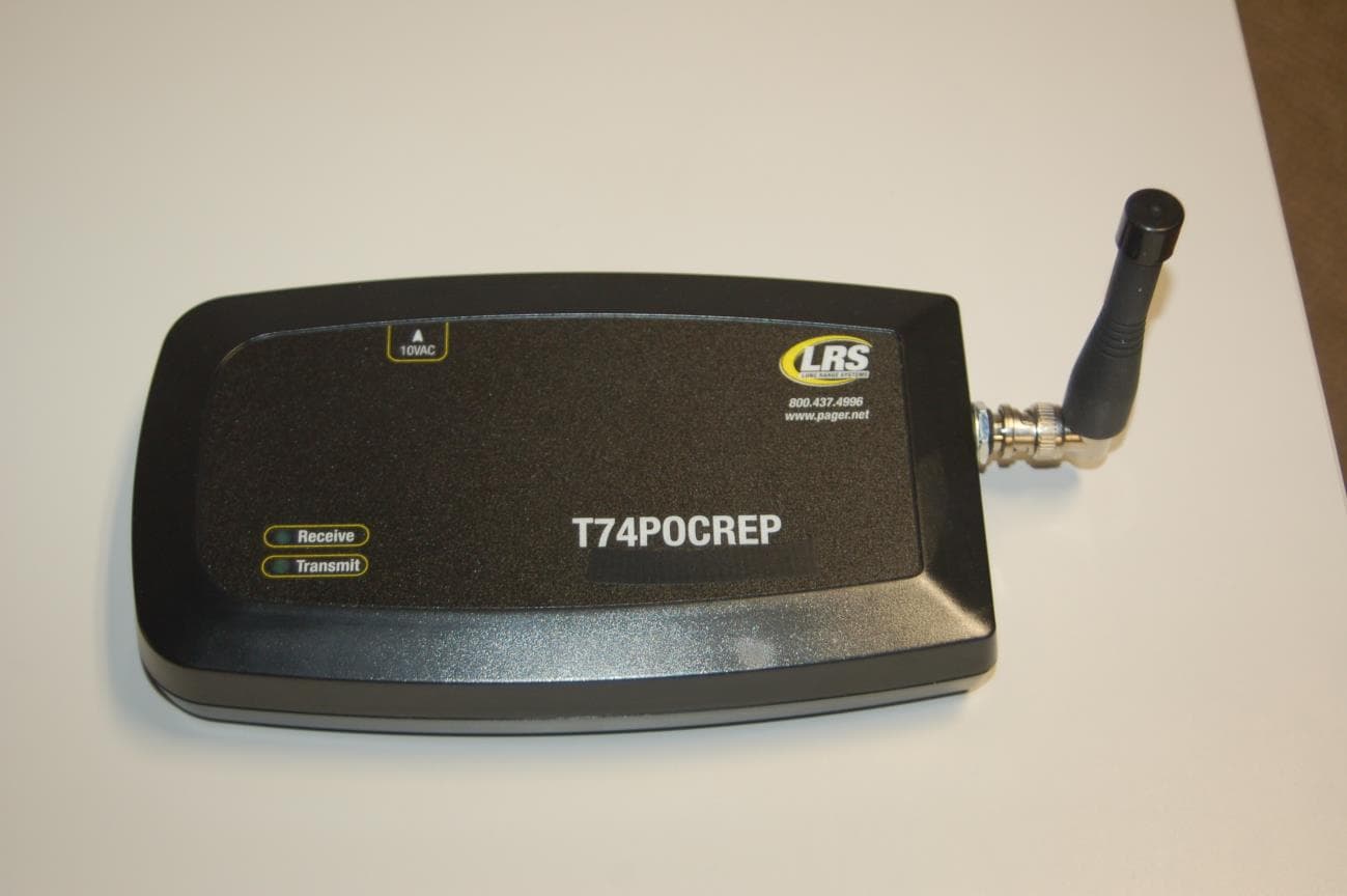
2AB6OTX3B25A
Sep 17, 2014Short range push for service transceiver
Equipment Class
DTS - Digital Transmission System