2AB6OTX7471Paging transmitter
Long Range Solutions, LLC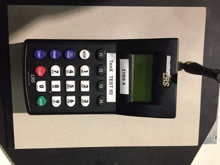
Click to zoom
Application Details
- Equipment Class
- TNB - Licensed Non-Broadcast Station Transmitter
- Date of Grant
- Mar 11, 2020
- Application Purpose
- Original Equipment
- Date of Application
- Mar 10, 2020
- Equipment Note
- Paging transmitter
- Frequency Range
- 434.00000000 - 469.15000000
- Company
- Long Range Solutions, LLC
- Country
- United States
Documents & Files
Document Text
Text extracted from the exhibit documents filed with the FCC. Open a document above to read the original.
Users Manual
Long Range Systems, LLC 1155 Kas Drive, Suite 150 Richardson, TX 75081 800.577.8101 lrsus.com LRS Connect Transmitter TX-7471 USER MANUAL Table Of Contents Installation and Setup . . . . . . . . . . . . . . . . . . . . . . . . . . . . . . . . . . . . . . . . . . . . . . . . . . . . 4 Hardware Provided ............................................................. 4 Installation Procedure ........................................................... 4 Connections ................................................................... 4 Keypad Description ............................................................. 5 Initial Power Up and Time Set ..................................................... 6 LRS Connect Reporting Set Up .................................................... 6 Transmitter Connectivity Status ................................................... 6 Changing the Time of LRS Connect Uploads ......................................... 7 Resetting Statistics ............................................................. 7 LRSN vs CoAP Steps ............................................................ 7 Basic Paging Operation Guide . . . . . . . . . . . . . . . . . . . . . . . . . . . . . . . . . . . . . . . . . . . . . 8 Page Guest Pagers .............................................................. 8 Page Individual Staff Pagers ...................................................... 8 Page a Cell Phone .............................................................. 9 Canned or Special Alphanumeric Messages ......................................... 9 Canned Message .............................................................. 10 Special Functions . . . . . . . . . . . . . . . . . . . . . . . . . . . . . . . . . . . . . . . . . . . . . . . . . . . . . . . . 11 Theft-Deterrent Function ........................................................ 11 Tracking ...................................................................... 12 Custom Tracking ............................................................... 12 Group Paging .................................................................. 13 Manager Mapping .............................................................. 13 Dry Contact ................................................................... 14 Set Alarms .................................................................... 16 Feature Setup Procedures . . . . . . . . . . . . . . . . . . . . . . . . . . . . . . . . . . . . . . . . . . . . . . . . . 17 User Password ................................................................. 17 Set Manager Password .......................................................... 17 Set Page Mode ................................................................. 17 Enable Guest Sessions Reporting .................................................. 18 Set to Page Staff or Guest Pagers .................................................. 19 Create Alphanumeric Messages ................................................... 19 Setting System Time/Date for LRS Connect Transmitter ................................ 20 Repeat Delay .................................................................. 21 ID Span ...................................................................... 21 Alphanumeric Pager Button Enable/Disable ......................................... 21 Freeform Messages ............................................................. 21 Alpha Vibration Level ........................................................... 21 Long Range Systems 1 LRS Connect Transmitter User Manual Guest Message ................................................................ 22 Display the Prompt ............................................................. 22 Display the Staff Prompt ......................................................... 22 Using Canned Messages in Staff and Guest Display Prompt ............................. 23 Staff Message ................................................................. 24 Alpha Pager Communication Baud Rate ............................................. 25 Maintenance Functions . . . . . . . . . . . . . . . . . . . . . . . . . . . . . . . . . . . . . . . . . . . . . . . . . . . 26 Paging Types in Mixed Systems ................................................... 26 Station ID ..................................................................... 26 Adjust Transmit Power. . . . . . . . . . . . . . . . . . . . . . . . . . . . . . . . . . . . . . . . . . . . . . . . . . . . . . . . . . . 27 Locating Misplaced Pagers ....................................................... 27 Cell Phone Paging/Messaging . . . . . . . . . . . . . . . . . . . . . . . . . . . . . . . . . . . . . . . . . . . . . . 28 Overview ..................................................................... 28 System Requirements ........................................................... 28 Programming Pagers . . . . . . . . . . . . . . . . . . . . . . . . . . . . . . . . . . . . . . . . . . . . . . . . . . . . . 30 Individual Pagers ............................................................... 30 Program Pager Groups ........................................................... 32 Alpha Encryption ............................................................... 33 Program Pager Vibration ......................................................... 34 Program Welcome Message ...................................................... 34 Wait Reducer . . . . . . . . . . . . . . . . . . . . . . . . . . . . . . . . . . . . . . . . . . . . . . . . . . . . . . . . . . . 35 USB . . . . . . . . . . . . . . . . . . . . . . . . . . . . . . . . . . . . . . . . . . . . . . . . . . . . . . . . . . . . . . . . . 35 Repeater Function . . . . . . . . . . . . . . . . . . . . . . . . . . . . . . . . . . . . . . . . . . . . . . . . . . . . . . 39 Positioning & Installing the Repeater ............................................... 39 System Specifications . . . . . . . . . . . . . . . . . . . . . . .…
Text truncated - open the document above for the full version.
Users Manual
TX-7471-C232 Paging System Transmitter Long Range Systems, LLC. LRSUS.COM | 800.437.4996 | 214.553.5308 USER MANUAL XU-0157 Rev. A R S -232 Receive Transmit P o w e r FC C ID : 2 A B 6 O 7 4 7 1 TX-7471-C232 L R S U S . CO M 1 2 V D C 4 A M 2 - 0 1 3 8 R ev. B TABLE OF CONTENTS Installation and Setup ......................................................................................................................................................................... 2 Set Restaurant ID ...................................................................................................................................................................... 4 Repeat Delay ............................................................................................................................................................................. 5 High Power Setting .................................................................................................................................................................. 5 Positioning and Installing the Repeater ...................................................................................................................................6 Service Questions and Answers ......................................................................................................................................................... 7 Warranty .............................................................................................................................................................................................. 7 FCC Statement ..................................................................................................................................................................................... 8 Terms & Conditions ............................................................................................................................................................................ 9 2 3 INSTALLATION AND SETUP Basic Installation 1) Connect the antenna 2) Plug the 12V power supply into the side of the Transmitter. 3) Connect the serial cable from the connector on the Transmitter to the serial port on the host computer. 4) Note the COM Port that the serial cable is connected to on the host computer. 5) Open HyperTerminal on the host computer. 6) Assign a Name for the new connection. 7) Select the COM Port coming from the serial cable. 8) Use the following settings: Bits per second: 9600 Data bits: 8 Parity: None Stop bits: 1 Flow control: None 8) Type ECHO1 and press ENTER. (This echo function will allow you to see what is being typed.) Screen View of Typing ECHO Screen View of ECHO ON 9) You are now ready to use the interface. Note: At any time, use the STAT command to view any changes. Set Restaurant ID This must be set correctly to page pagers. To set the Restaurant ID, type RID,x and press ENTER twice. X is the Restaurant ID. Example: To set an ID of 2, type RID,2 and press ENTER twice. Example Restaurant ID to 2 HyperTerminal Output Showing ID as 2 Type STAT and press ENTER Status View Showing Restaurant ID as 2 4 Repeat Delay To turn ON Repeat Delay, type RPTDLY,1 and press ENTER twice. To turn OFF Repeat Delay, type RPTDLY,0 and press ENTER twice. Example Repeat Delay ON Status View Showing Repeat Delay ON High Power Setting To change the Power Setting, type HWPR,x and press ENTER twice. X is the Power Setting, a value of 0 to 4. Example: To set a Power Setting of 3, type HWPR,3 and press ENTER twice. Example High Power Set to 1 HyperTerminal Output Showing High Power Set to 1 Status View Showing High Power Set to 1 5 POSITIONING AND INSTALLING THE REPEATER Note: The best place to mount your repeater is on a ceiling or wall that is very high. The idea is to get the signal as high as possible so it “umbrellas” the guest and thus all pagers can receive it. The repeater operates at its best when installed at the “fringe” of your area. This means you should get it as far from the transmitter as possible but still be able to receive the transmitter’s signal. 1. Locate a 110V outlet near the selected installation location. 2. Plug the power adapter into the outlet and into the power connector hole on the side of the repeater. 3. Ensure that when power is plugged in, the Red RECEIVE light will blink continuously to indicate power is on and the unit is operating. 4. Place the paging transmitter in “Range Test Mode” (see transmitter’s operating instructions). 5. Ensure the Red TRANSMIT light periodically alternate flashes on about every 5 seconds. • If the periodic TRANSMIT flash does not occur, move the repeater closer to the transmitter and try again. • Keep moving the repeater toward the transmitter until the TRANSMIT flash occurs. • After establishing the correct distance, mount the repeater as high as possible. Transmitter Repeater Extended Range Normal Range 6 SERVICE QUESTIONS AND ANSWERS What to do if the system malfunctions Should your paging system ever fail or should you need additional paging supplies, call Long Range Systems at (800) 437-4996. System Repair After Warranty Expiration Call Long Range Systems before sending a non-warranty item in for repair. Ordering Additional Pagers Call Long Range Systems at 800.437.4996 or 214.553.5308 to place your order. Loss Deterrent and Recovery Return address labels on the back of all of your equipment are highly recommended. Should any of your pagers be taken off premise, this will help them find their way back to you. You may order return address labels from LRS or print them yourself. Power Over Connector Previous hardware revisions of the T7471-C232 would deliver 5 VDC on pin 9 of the DE-9 serial connector. Please be advised that current hardware revisions no longer do this. WARRANTY Long Range Systems, LLC. warrants this product against any defects that are due to faulty material or workman- ship for a one-year period after the original date of consumer purchase of…
Text truncated - open the document above for the full version.
External Photos
21168 External Photos Page 1 of 6 Side 1 of 6 Side 2 Side 3 Side 4 Side 5 Side 6 of 6 ***
ID Label/Location Info
Long Range Systems LABEL ART AND SPECS CONTACT: SIZE: COLORS: MATERIAL: THICKNESS: FINISHING: Dani Chandler - [email protected] 1.99” x 0.996“” black, white Velvet Lexan Sheets M1-0187 Rev. A PART NO: 02-25-20 Long Range Systems, LLC FCC ID: 2AB6OTX7471 IC: 5501A-TX7471 MODEL: TX-7471 This device complies with part 15 of the FCC Rules. Operation is subject to the following two conditions: (1) This device may not cause harmful interference, and (2) this device must accept any interference received, including interference that may cause undesired operation. 1.99” x 0.996” (Actual Size Shown) Die Cut
ID Label/Location Info
Long Range Systems LABEL ART AND SPECS 02-20-20 TX-T7471-C232 FCC Label Placement & Dimensions Label Part No. M2-0188 Rev A & M1-0105 Rev B Label goes hereLabel goes here 2.03” x 0.55” (M1-0105) 1.86” x 0.3” (M2-0188) Long Range Systems, LLC IC: 5501A-TX7471 FCC ID: 2AB6OTX7471 MODEL: TX-7471-C232 This device complies with part 15 of the FCC Rules. Operation is subject to the following two conditions: (1) This device may not cause harmful interference, and (2) this device must accept any interference received, including interference that may cause undesired operation.
Internal Photos
21168 TX-7471 Internal Photographs Page 1 of 3 21168 TX-7471 Internal Photographs Page 2 of 3 21168 TX-7471 Internal Photographs Page 3 of 3 ***
RF Exposure Info
21168 TX-7471: Exposure Supplemental Report Page 1 of 2 Professional Testing (EMI) Inc. 1601 North A.W. Grimes Blvd., Suite B Round Rock, TX 78665 e-mail: [email protected] (512) 244-3371 Fax: (512) 244-1846 1.0 Maximum Permissible Exposure Evaluation (Supplements the test report.) The measured power is considered for the intended use of the device and resulting RF exposure to the user. 1.2 Criteria Section Reference Date FCC KDB 447478 D01 // RSS-102 Issue 5 24 Feb 2020 1.3 Procedure Using measurement of peak power and considering the intended application, determine the permissible exposure level, applicability of exclusion, or whether additional exposure tests (SAR) are indicated. When applicable justify conclusion for selected exposure level and separation distance. 1.4 Source Duty Cycle Measurement Duty cycle was measured with the EUT in normal operating mode with 4 fastest possible successive paging entries each 1 digit long. Four 1.7 second transmissions were recorded in 13.9 second period. Duty cycle is therefore (4*1.7s)/13.9s = 48.9 %; yielding a factor of -3.1 dB. This yields a very conservative result as compared to typical single-patron paging events. 1.5 Spacing Measurement Spacing was determined by direct measurement from the nearest antenna surface to the nearest edge of the [Enter] key that triggers the transmitter. The result was 195 mm. For FCC a conservative distance of 190 mm is applied. For ISED it is rounded to 20 cm. Note that the nearest row of function keys [F1 to F4] is reserved for configuration or service diagnostics. 1.6 Power to Exposure Calculation Radio transmit power was determined by conducted measurement as cited in the test report. Table 1.6.1 Power Calculation for Exposure; Highest frequency 0.450575 GHz* Measured Conducted Power mW Calculated Peak EIRP dBm Source Duty Cycle Factor dB Antenna Gain dBi Calculated EIRP dBm EIRP In Linear Terms mW 1479 31.7 -3.1 0** 28.6 724 *Highest recorded power was at this frequency. **Shortened helical monopole ‘duck’ style antenna. 1.7 SAR Exemption Calculation – FCC 3.0 Criteria Applicable requirement: KDB 447498 Clause 4.3.1 21168 TX-7471: Exposure Supplemental Report Page 2 of 2 Professional Testing (EMI) Inc. [(724 mW)/(190 mm)] · [√0.450575 (GHz) ] = 2.6 Step 1 (Rounded to nearest tenth.) [2.6] + [(190 mm - 50 mm)·( 450.575 MHz /150)] mW = 423 mW Step 2 “ Appendix B SAR Exclusion Level (column 190 mm, row 450 MHz): 644 mW Apply Limb Exposure Factor (2.5), 644 mW * 2.5 = 1610 mW Adjust for Limb Exposure 423.0 mW < 1610 mW 1.8 SAR Exemption Calculation – ISED Exposure Calculation Per clause 2.5.2: “• at or above 300 MHz and below 6 GHz and the source-based, time-averaged maximum e.i.r.p. of the device is equal to or less than 1.31 x 10⁻² ƒ0.6834 W (adjusted for tune-up tolerance), where ƒ is in MHz;” S = 0.0131ƒ 0.6834 = 0.0131 (450.575) 0.6834 = 0.853 W Ref. RSS-102 clause 2.5.2 0.724 W < 0.853 W 1.9 Conclusion The device meets the exemption requirements for the respective agencies. Signed: Eric Lifsey ***
Test Report
Project 21168-15 TX-7471 LRS Paging Transmitter Wireless Certification Report Full Band Coverage Prepared for: Long Range Systems, LLC By Professional Testing (EMI), Inc. 1601 North A.W. Grimes Blvd., Suite B Round Rock, Texas 78665 19 Feb 2020 Reviewed by Written by Shakil Murad Lead EMC Engineer Eric Lifsey EMC Engineer TX-7471 by Long Range Systems, LLC 21168-15 Professional Testing (EMI) Inc. Page 2 of 40 Revision History Revision Number Description Date Draft 02 Draft for review. 21 Feb 2020 Final 01 24 Feb 2020 Final 02 Reconcile rated power with measurement and ISED tolerance. 10 Mar 2020 Errata: None. TX-7471 by Long Range Systems, LLC 21168-15 Professional Testing (EMI) Inc. Page 3 of 40 Table of Contents Revision History ............................................................................................................................................................ 2 Certificate of Compliance ............................................................................................................................................. 5 1.0 Introduction .......................................................................................................................................................... 6 1.1 Scope ............................................................................................................................................................... 6 1.2 EUT Description ............................................................................................................................................. 6 1.3 EUT Operation ................................................................................................................................................ 7 1.4 Modifications to Equipment ............................................................................................................................ 7 1.5 Test Site .......................................................................................................................................................... 7 1.6 Applicable Documents .................................................................................................................................... 7 1.7 Test Setup Diagram ......................................................................................................................................... 8 2.0 Conducted Output Power ..................................................................................................................................... 9 2.1 Procedure ........................................................................................................................................................ 9 2.2 Criteria ............................................................................................................................................................ 9 2.3 Results ............................................................................................................................................................. 9 2.4 Calculated Attenuation and Spurious Limits Beyond Authorized Bandwidth ................................................ 9 3.0 Emission Mask ................................................................................................................................................... 10 3.1 Procedure ...................................................................................................................................................... 10 3.2 Criteria .......................................................................................................................................................... 10 3.3 Results ........................................................................................................................................................... 10 4.0 Spurious Emissions at Antenna Terminals ........................................................................................................ 12 4.1 Procedure ...................................................................................................................................................... 12 4.2 Criteria .......................................................................................................................................................... 12 4.3 Results ........................................................................................................................................................... 12 4.3.1 Transmit Mode .................................................................................................................................... 13 4.3.2 Receive Mode ...................................................................................................................................... 14 5.0 Field Strength of Radiated Spurious Emissions ................................................................................................. 15 5.1 Procedure ...................................................................................................................................................... 15 5.2 Criteria .......................................................................................................................................................... 15 5.3 Results ........................................................................................................................................................... 15 5.3.1 Transmit Mode, Below 1 GHz, Bottom Channel ................................................................................ 16 5.3.2 Transmit Mode, Above 1 GHz, Bottom Channel ................................................................................ 18 5.3.3 Transmit Mode, Below 1 GHz, Middle Channel ................................................................................. 20 5.3.4 Transmit Mode, Above 1 GHz, Middle Channel .....................................…
Text truncated - open the document above for the full version.
Test Setup Photos
Radiated Emission, up to 1 GHz, Front Radiated Emission, up to 1 GHz, Back Radiated Emission, up to 5 GHz, Front Radiated Emission, up to 5 GHz, Back Frequency Stability, Temperature Frequency Stability, Voltage Conducted Measurements: Power, Mask, Bandwidth, Spurious Transmit Frequency Behavior ***
Contact Information
Applicant
Robert Pinell(Chief Officer)
Test Firm
Professional Testing (EMI), Inc.Larry Finn
Technical Specifications
| # | Rule Parts | Frequency Range | Power Output | Emission | Tolerance |
|---|---|---|---|---|---|
| 1 | 90 | 434 MHz - 469.15 MHz | 1.479 W | 8K79G1D | 218.0000000000 Hz |
Other Applications from Long Range Solutions, LLC

2AB6OTX7470
Apr 28, 2015Paging Transmitter for restaurant seating
Equipment Class
TNB - Licensed Non-Broadcast Station Transmitter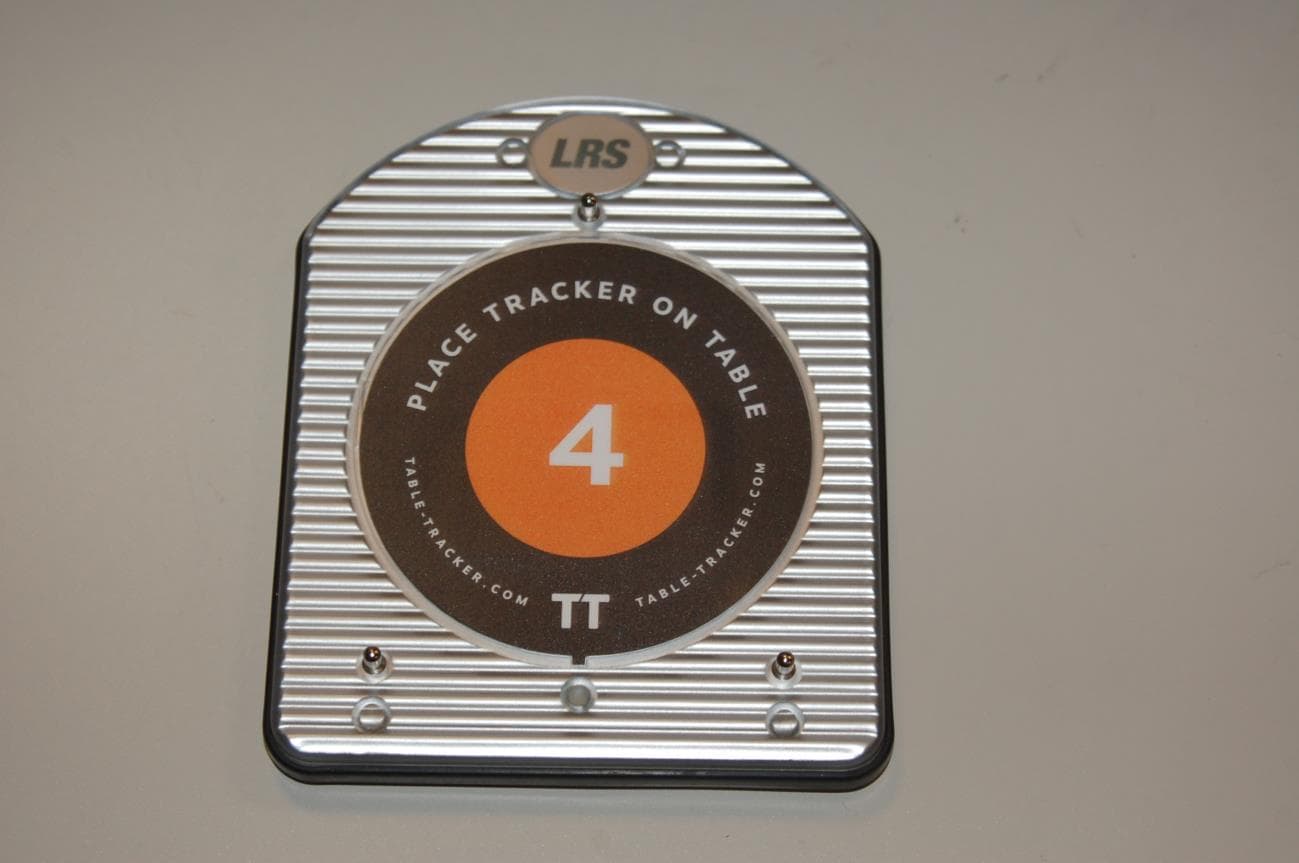
2AB6OTRACKER
Feb 23, 2015Table-Tracking Paging Receiver
Equipment Class
DXX - Part 15 Low Power Communication Device Transmitter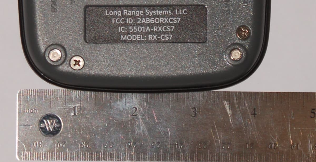
2AB6ORXCS7
Feb 12, 2015Paging Receiver
Equipment Class
DSC - Part 15 Security/Remote Control Transmitter
2AB6OTX3B25A
Sep 17, 2014Short range push for service transceiver
Equipment Class
DTS - Digital Transmission System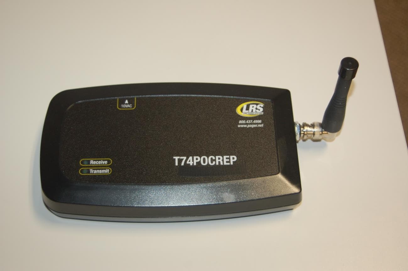
2AB6OTR7400
Sep 17, 2014Short range paging system transmitter
Equipment Class
TNB - Licensed Non-Broadcast Station Transmitter