2AB6ORXCS7Paging Receiver
Long Range Solutions, LLC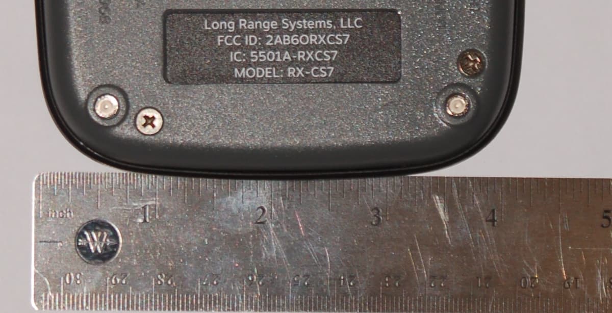
Click to zoom
Application Details
- Equipment Class
- DSC - Part 15 Security/Remote Control Transmitter
- Date of Grant
- Feb 12, 2015
- Application Purpose
- Original Equipment
- Date of Application
- Feb 12, 2015
- Equipment Note
- Paging Receiver
- Frequency Range
- 467.75000000 - 467.75000000
- Company
- Long Range Solutions, LLC
- Country
- United States
Documents & Files
Document Text
Text extracted from the exhibit documents filed with the FCC. Open a document above to read the original.
Users Manual
Coaster Call GUEST PAGING RECEIVER MODELS: RX-CS6, RX-CS7, & RX-AT9 Long Range Systems, LLC. LRSUS.COM | 800.437.4996 | 214.553.5308 USER MANUAL USER MANUAL | RX-CS6, RX-CS7, & RX-AT9 LRSUS.COM | 2 TABLE OF CONTENTS General Information 3 Setup and Use 3 Charger Installation 3 Operation 3 Product Specifications 3 Troubleshooting 4 Service Questions and Answers 5 What To Do If The System Malfunctions 5 System Repair After The Warranty Expires 5 Ordering Additional Pagers 5 Loss Deterrent and Recovery 5 Warranty 5 FCC Information 6 USER MANUAL | RX-CS6, RX-CS7, & RX-AT9 LRSUS.COM | 3 GENERAL INFORMATION The guest pagers are used in conjunction with the LRS transmitters. The coasters are used as an on-premise paging system to increase efficiency by alerting customers who are waiting, usually for services or goods. SETUP AND USE The low profile devices are rechargeable, water resistant, and can flash, vibrate, beep or any combination thereof when called by an LRS transmitter. To begin using your pagers, locate the charging base near a power outlet and charge them for 16 hours. Charger Installation Install the charger base per the directions received with the charger kits. Operation 1. When a guest arrives, remove a pager from the charging stack. Pagers will light up and or vibrate for 2 seconds. 2. Record the pager number and hand to your guest. 3. Page the pager by entering the number into the transmitter. 4. LRS guest pagers will flash, vibrate and or beep depending on the page mode sent by the transmitter. 5. Transmitters can also send predefined time limits for each of the pager alert modes. See transmitter manual for details. PRODUCT SPECIFICATIONS Required Voltage: 110-120V outlet for pager chargers, LRS issued 12VAC, 4A power supply included in kit Battery Type: Nickel Metal Hydride (NiMH). Rechargeable. Battery Life: Approximately 3-5 years Battery Charge Life: Approximately 24 hours (depends on how often they are paged). Recharge time: 16 hours minimum from completely discharged. Operating Range: Up to 1/4 mile Dimensions: 4.25” x 4.25” x .75” USER MANUAL | RX-CS6, RX-CS7, & RX-AT9 LRSUS.COM | 4 TROUBLESHOOTING Pager Does Not Receive Pages 1. Be sure that the pagers are charged. 2. Be sure transmitter power is plugged in and display is lit. • If display is blank, check power supply as described below. • If display is lit, check transmitter functions described below. 3. Pagers will flash and may or may not vibrate depending on a preprogrammed configu- ration when removed from the charger base. Check The Power Supply 1. Be sure the wall outlet that the power supply is plugged into is working (plug another device into it and see that it works properly). 2. Be sure the wire that plugs into the side of the transmitter is plugged in securely. 3. Try plugging the power supply that is powering the charger into the transmitter. • If the transmitter powers up from a known good power supply, but not from the charger power supply, you probably have a bad charger power supply. Call Long Range Systems for a replacement or repair. Charging Check Please take note of the following charging requirements and functions. 1. A maximum of 15 pagers may be stacked on one charging base at a time. 2. If your system has more than 15 pagers and you only have one charging base, call Long Range Systems to purchase additional. 3. If your system has 2 or more charging bases, check that the jumper wires between the bases are connected securely. 4. Pagers on charge will flash a red LED light every 5 seconds, forming an upward moving red light on the pager stack. 5. A maximum of 4 charging bases per power supply are allowed. 6. Check for dirty charging pins on your coasters. To clean, use a damp rag, and wipe the 4 metal contacts on the front and back of each pager. 7. Be sure that all pagers are plugged in and charging when not in use. Even for long periods of inactivity. USER MANUAL | RX-CS6, RX-CS7, & RX-AT9 LRSUS.COM | 5 SERVICE QUESTIONS AND ANSWERS What to do if the system malfunctions Should your paging system ever fail to function properly, refer to the previous trouble- shooting section. If you’ve followed all the steps and requirements and your system is still inoperable, you may submit a support request at support.LRSUS.com or call Long Range Systems at (800) 437-4996 Monday through Friday 8:30 am to 5:00 pm Central Time. For after hours inquiries, please follow the instructions on the support line. LRS Custom- er Support will return the call as soon as possible. Please keep in mind that options are limited over the weekend. System Repair After Warranty Expiration Call Long Range Systems before sending a non-warranty item in for repair. Ordering Additional Pagers Call Long Range Systems at 800.437.4996 or 214.553.5308 to place your order. Loss Deterrent and Recovery Return address labels on the back of all of your equipment are highly recommended. Should any of your pagers be taken off premise, this will help them find their way back to you. You may order return address labels from LRS or print them yourself. WARRANTY Long Range Systems, LLC. warrants this product against any defects that are due to faulty material or workmanship for a one-year period after the original date of consumer purchase of the complete paging system (transmitter, pagers, and charger). This warranty does not include damage to the product resulting from accident, misuse or improper elec- trical connection. If this product should become defective within the warranty period, we will repair or replace with equivalent product, free of charge. We will return your product, transportation charges prepaid standard FedEx Ground shipping, provided the product is shipped prepaid to: Long Range Systems, LLC. 4550 Excel Pkwy., Suite 200 Addison, TX 75001 No return or replacement can be received without prior authorization and the proper RMA# posted to the outside of the shipping container. This warranty gives you specific legal rights and you may…
Text truncated - open the document above for the full version.
Attestation Statements
Long Range Systems, LLC 4550 Excel Pkwy, Suite 200 | Addison, TX 75001 | 214.553.5308 lrsus.com LONG RANGE SYSTEMS, LLC 4550 Excel Parkway, Suite 200 Addison, TX 75001 Greetings, The RX-AT9, RX-CS7 and RX-CS6 are based on a common electrical and mechanical design platform. The AT-9 and CS-7 possess the superset of features with only a minor variation in top cover design that sets them apart. They are electrically identical at the PCBA level. This full-featured PCBA was used for all regulatory testing and for business reasons, the RX-CS7 plastic housing (top cover) was made available before the RX-AT9. To illustrate the difference in the top covers, three exploded assembly views are presented below. The RX-CS7 top cover (item 6 in its drawing) is mechanically identical to the RX-AT9 top cover (item 4 in its drawing) except for the RX-AT9 addition of a Clear Cover (item6) that is used to secure a paper advertising label (item 8). This is the only difference between the RX-CS7 and the RX-AT9. Long Range Systems, LLC 4550 Excel Pkwy, Suite 200 | Addison, TX 75001 | 214.553.5308 lrsus.com Long Range Systems, LLC 4550 Excel Pkwy, Suite 200 | Addison, TX 75001 | 214.553.5308 lrsus.com Long Range Systems, LLC 4550 Excel Pkwy, Suite 200 | Addison, TX 75001 | 214.553.5308 lrsus.com Long Range Systems, LLC 4550 Excel Pkwy, Suite 200 | Addison, TX 75001 | 214.553.5308 lrsus.com The RX-CS6 and RX-CS7 both have hardware available so photographs can be presented to illustrate the differences between them. Fully assembled versions of both products are pictured below. Plastic housings are identical with the exception of a small, clear light pipe in the upper right hand corner on the bottom of the RX-CS7. Labeling differences on the top cover are self-evident in the photos. Long Range Systems, LLC 4550 Excel Pkwy, Suite 200 | Addison, TX 75001 | 214.553.5308 lrsus.com Long Range Systems, LLC 4550 Excel Pkwy, Suite 200 | Addison, TX 75001 | 214.553.5308 lrsus.com Photographs of the PCBAs are shown below to illustrate the electrical differences in how the common PCB is populated. From the top view, the following differences can be observed: Battery pack size o 3-cell, full AAA on the RX-CS7 o 2-cell, 2/3 AAA on the RX-CS6 7-segment LED display on the RX-CS7 LED type found along the periphery (4 corners and 4 sides) o Tri-color RGB LEDs on the RX-CS7 o Single-color red LEDs on the RX-CS6 Resistors & transistors to support LED drive The battery size difference is associated with the amount of LED drive current required by each product variant. Also note the common, identical features: Radio transceiver circuitry (top center, above the battery) PCB antenna (top left corner area) MCU (lower right corner area) Battery charging circuitry (right center area) Long Range Systems, LLC 4550 Excel Pkwy, Suite 200 | Addison, TX 75001 | 214.553.5308 lrsus.com The back side of the PCBA is shown below. The only difference to note is that the RX-CS6 does not have an LED and a Phototransistor populated in the upper, right corner. These parts support light communication between stacked RX-CS7s. Long Range Systems, LLC 4550 Excel Pkwy, Suite 200 | Addison, TX 75001 | 214.553.5308 lrsus.com I hope this helps to illustrate the differences in our products being submitted and why the CS-7 was chosen as a representative sample for testing purposes. If you have any questions about what is contained here, please feel free to contact me directly. Thank you, Ken Pelic - Sr. Hardware Engineer Long Range Systems 4550 Excel Pkwy, Addison, TX 75001 214-543-3089 mobile 972-674-4428 direct [email protected] www.lrsus.com
ID Label/Location Info
Long Range Systems LABEL ART AND SPECS 02-03-15 50.75 mm x 15.15 mm AT 9 FCC Label Placement & Dimensions Label Part No. M1-0095 Long Range Systems, LLC FCC ID: 2AB6ORXCS7 IC: 5501A-RXCS7 MODEL: RX-AT9
ID Label/Location Info
Long Range Systems LABEL ART AND SPECS 01-19-15 Long Range Systems, LLC FCC ID: 2AB6ORXCS7 IC: 5501A-RXCS7 MODEL: RX-CS7 51.81 mm x 16.21 mm CS7 FCC Label Placement & Dimensions Label Part No. M1-0094
RF Exposure Info
16179 Exposure Supplemental Report Rev00 Page 1 of 2 Professional Testing (EMI) Inc. 1601 North A.W. Grimes Blvd., Suite B Round Rock, TX 78665 e-mail: [email protected] (512) 244-3371 Fax: (512) 244-1846 Equipment Evaluated for Exposure Manufacturer Model(s) Long Range Systems RX‐CS7, RX‐CS6, RX‐AT9 SAR Exclusion Justification Applying test exclusion thresholds for 100 MHz to 6 GHz at test separation distances ≤ 50 mm. Guidance document reference: 447498 D01 General RF Exposure Guidance v05r01, page 11, paragraph 4.3.1(1). The 1‐g and 10‐g SAR test exclusion thresholds for 100 MHz to 6 GHz at test separation distances ≤ 50 mm are determined by: [(max. power of channel, including tune‐up tolerance, mW)/(min. test separation distance, mm)] * [√f(GHz)] ≤ 3.0 for 1‐g SAR and ≤ 7.5 for 10‐g extremity SAR, where • f(GHz) is the RF channel transmit frequency in GHz • Power and distance are rounded to the nearest mW and mm before calculation • The result is rounded to one decimal place for comparison • 3.0 and 7.5 are referred to as the numeric thresholds The test exclusions are applicable only when the minimum test separation distance is ≤ 50 mm and for transmission frequencies between 100 MHz and 6 GHz. When the minimum test separation distance is < 5 mm, a distance of 5 mm according to 5) in section 4.1 is applied to determine SAR test exclusion. SAR test exclusion analysis: Assumptions: The minimum separation distance of 5 mm is assumed per the guidance document. Max. power of channel: 0.03 mW, rounded to 1 mW Min. separation distance: 5 mm Max. frequency: 0.46775 GHz Calculation: [(Pwr/Dist)*Sqrt(Freq.)] = 0.14, or rounded up to 0.2 The result of the above SAR threshold calculation demonstrates that the result is less than the 1‐g numeric threshold of 3 and the 10‐g numeric threshold of 7.5. Conclusion: The above analysis shows that the digital transmission system transceiver named above qualifies for exemption from SAR testing. 16179 Exposure Supplemental Report Rev00 Page 2 of 2 Professional Testing (EMI) Inc. Signed: Eric Lifsey ***
Test Report
1601 North A.W. Grimes Blvd., Suite B Round Rock, TX 78665 e-mail: [email protected] (512) 244-3371 Fax: (512) 244-1846 February 9, 2015 John Weber Long Range Systems, LLC 4550 Excel Parkway Suite 200 Addison TX 75001 Dear John: Thank you for allowing Professional Testing (EMI), Inc. an opportunity to perform testing for Long Range Systems, LLC. Enclosed is the Wireless Certification Report for the RX-CS7 Pager. This report can be used to demonstrate compliance with wireless regulatory requirements for wireless devices in North America. If you have any questions, please contact me. Sincerely, Jeffrey A. Lenk President Attachment Wireless Certification Report: RX-CS7, RX-CS6, RX-AT9 16179-15 Professional Testing (EMI) Inc. Page 2 of 36 Project 16179-15 RX-CS7, RX-CS6, RX-AT9 Wireless Pager Wireless Certification Report Prepared for: Long Range Systems, LLC 4550 Excel Parkway Suite 200 Addison TX 75001 By Professional Testing (EMI), Inc. 1601 North A.W. Grimes Blvd., Suite B Round Rock, Texas 78665 February 9, 2015 Reviewed by Written by Larry Finn Chief Technology Officer Eric Lifsey Test Engineer Wireless Certification Report: RX-CS7, RX-CS6, RX-AT9 16179-15 Professional Testing (EMI) Inc. Page 3 of 36 Revision History Revision Number Description Date 01 Initial draft. 2014‐10‐07 02 Revised per client comments; added new data. 2015‐02‐09 03 Revised per client comments. 2015‐02‐09 Wireless Certification Report: RX-CS7, RX-CS6, RX-AT9 16179-15 Professional Testing (EMI) Inc. Page 4 of 36 Table of Contents Revision History ............................................................................................................................................................. 3 Certificate of Compliance ............................................................................................................................................. 6 1.0 Introduction.......................................................................................................................................................... 7 1.1 Scope ............................................................................................................................................................... 7 1.2 EUT Description ............................................................................................................................................. 7 1.3 EUT Operation ................................................................................................................................................ 7 1.4 Modifications to Equipment ............................................................................................................................ 8 1.5 Test Site .......................................................................................................................................................... 8 1.6 Radiated Measurements .................................................................................................................................. 8 2.0 Applicable Documents and Clauses ..................................................................................................................... 9 3.0 Fundamental Field Strength ............................................................................................................................... 10 3.1 Test Procedure .............................................................................................................................................. 10 3.2 Test Criteria .................................................................................................................................................. 10 3.3 Test Results ................................................................................................................................................... 10 4.0 Transmitter Duty Cycle and Shutoff Time ........................................................................................................ 11 4.1 Test Procedure .............................................................................................................................................. 11 4.2 Test Criteria .................................................................................................................................................. 11 4.3 Test Results ................................................................................................................................................... 11 4.3.1 Shut Off Timing Measurement ............................................................................................................ 12 5.0 Occupied Bandwidth ......................................................................................................................................... 13 5.1 Test Procedure .............................................................................................................................................. 13 5.2 Test Criteria .................................................................................................................................................. 13 5.3 Test Results ................................................................................................................................................... 13 5.3.1 Bandwidth Plot .................................................................................................................................... 14 6.0 Radiated Spurious Emissions Below 1 GHz ...................................................................................................... 15 6.1 Test Procedure .............................................................................................................................................. 15 6.2 Test Criteria .................................................................................................................................................. 15 6.3 Test Results ......................…
Text truncated - open the document above for the full version.
Test Setup Photos
16179 Setup Photographs Page 1 of 4 FUNDAMENTAL AND SPURIOUS, FRONT VIEW FUNDAMENTAL AND SPURIOUS, BACK VIEW 16179 Setup Photographs Page 2 of 4 FUNDAMENTAL AND SPURIOUS, CLOSE UP DUTY CYCLE, BANDWIDTH 16179 Setup Photographs Page 3 of 4 16179 Setup Photographs Page 4 of 4 THE FOLLOWING ARE ADDITIONAL RECEIVE/CHARGING MODE EMISSION MEASUREMENTS FOR REV 5 Front Rear ***
Contact Information
Applicant
Robert Pinell(Chief Officer)
Test Firm
Professional Testing (EMI), Inc.Larry Finn
Technical Specifications
| # | Rule Parts | Frequency Range | Power Output |
|---|---|---|---|
| 1 | 15.231 | 467.75 MHz - 467.75 MHz | - |
Other Applications from Long Range Solutions, LLC
2AB6OTX7471
Mar 11, 2020Paging transmitter
Equipment Class
TNB - Licensed Non-Broadcast Station Transmitter
2AB6OTX7470
Apr 28, 2015Paging Transmitter for restaurant seating
Equipment Class
TNB - Licensed Non-Broadcast Station Transmitter
2AB6OTRACKER
Feb 23, 2015Table-Tracking Paging Receiver
Equipment Class
DXX - Part 15 Low Power Communication Device Transmitter
2AB6OTX3B25A
Sep 17, 2014Short range push for service transceiver
Equipment Class
DTS - Digital Transmission System
2AB6OTR7400
Sep 17, 2014Short range paging system transmitter
Equipment Class
TNB - Licensed Non-Broadcast Station Transmitter