2AB6OTX3B25AShort range push for service transceiver
Long Range Solutions, LLC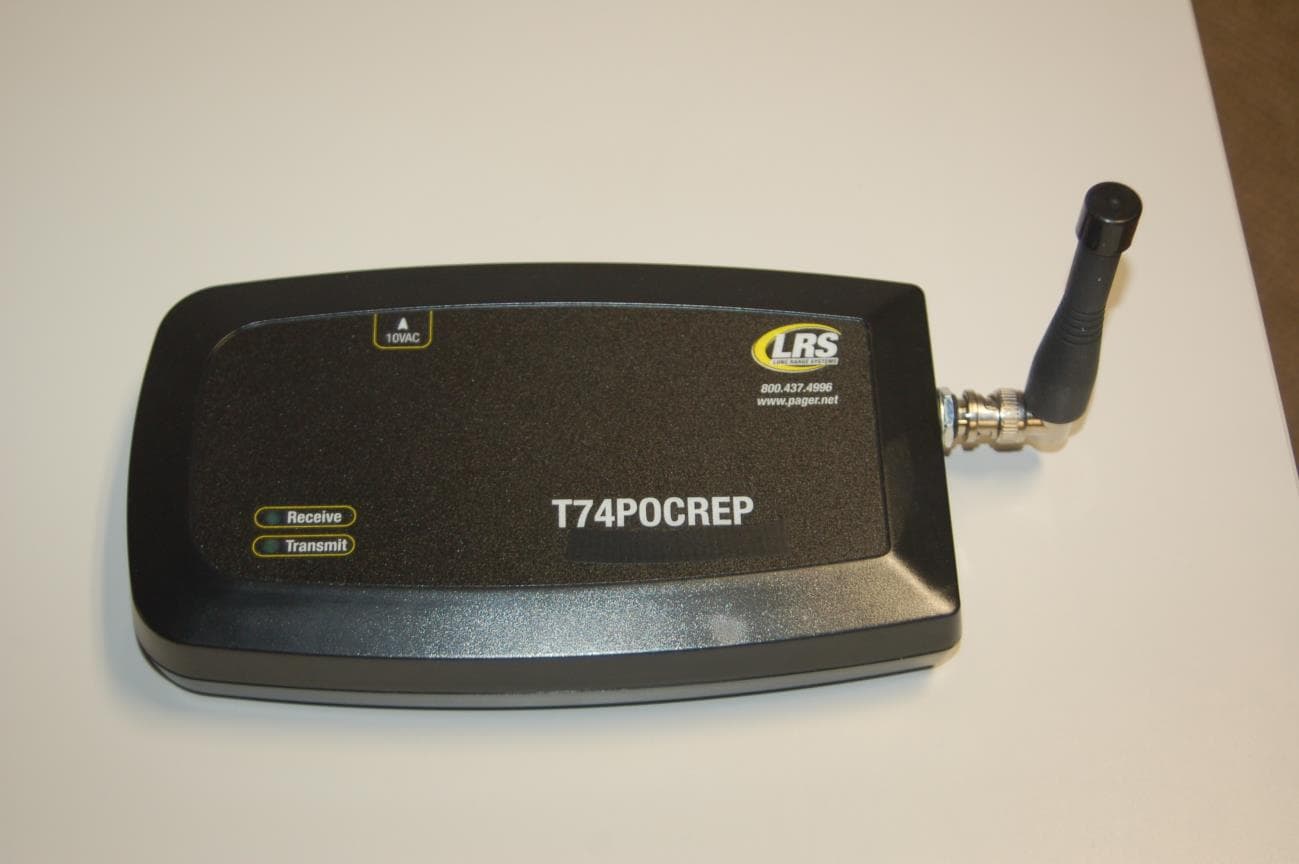
Click to zoom
Application Details
- Equipment Class
- DTS - Digital Transmission System
- Date of Grant
- Sep 17, 2014
- Application Purpose
- Original Equipment
- Date of Application
- Sep 17, 2014
- Equipment Note
- Short range push for service transceiver
- Frequency Range
- 2405.00000000 - 2480.00000000
- Company
- Long Range Solutions, LLC
- Country
- United States
Documents & Files
Document Text
Text extracted from the exhibit documents filed with the FCC. Open a document above to read the original.
Users Manual
To Assemble the Table Genie 1. Remove Table Genie from packaging. 2. Contents will include: • 1 Table Genie • 1 Table Plate • 1 Double-side foam tape • 1 AA Battery 3. Pull the release tab back, then lift and remove the battery cover. 4. Insert the AA battery. 5. Reassemble the Table Genie To Mount the Table Genie To the Table: 1. Choose to either use Double sided Foam Tape or 3 screws to hold the Table Plate to the Table. 2. Secure Table Plate to the Table. 3. Slide the Table Genie onto the Table Plate. Push For Service Monitor 1. Press ENTER. 2. Press EXIT. Long Range Systems1Table Genie Quick Guide Table Genie System Interface Transmitter QUICK SETUP & OPERATION Release Tab of Battery Cover Pull in Direction of Arrows Battery Push For Service www.pager.net Associating Table Genie 1. From the Setup menu select SYSTEM TOOLS. 2. Select WPAN. 3. Select Associate (the unit will stay in associate for 5 minutes and then associate will have to be restarted.) 4. Install a battery in the Table Genie and press all 3 buttons after the unit begins to flash. Then: • The buttons will light back and forth. • The buttons will flicker rapidly. • The buttons will go out. • The popup will ask for the entry of a table number. 5. Repeat steps 3 and 4 until all units are associated. 6. To exit, press EXIT on T7502. Note: If unit fails to join, remove battery, put unit aside, and repeat process after all other units are joined. Operation 1. When a button is pressed on the Table Genie, a table number will be displayed and timer will start on the monitor. 2. The last pressed button on the Table Genie will blink until cleared. 3. To clear a unit, use the user defined cancel sequence (see user manual to change.) 4. When cleared, the button will stop flashing and the monitor will clear. 5. If the table monitor is not cleared • Within a preset time, the color for that table will change to yellow. • If the table is still not cleared after another preset time, the monitor for that table will turn red and the manager will be paged. • The manager will periodically be re-paged until the table is cleared. Setup for Table Genie Operation From the Setup menu select GLOBAL SETTINGS. 1. Select OPERATION MODE then Push For Service Monitor 2. Press ENTER. 3. Press EXIT. This device complies with Part 15 of the FCC Rules. Operation is subject to the following two conditions: (1) This device may not cause harmful interference, and (2) this device must accept any interference received, including interference that may cause harmful interference. Warning: Changes or modifications not expressly approved by Long Range Systems could void the user's authority to operate the equipment. Long Range Systems2Table Genie Quick Guide XU-0058 091114
ID Label/Location Info
Long Range Systems LABEL ART AND SPECS 06-10-14 TR-7400 FCC Label Placement & Dimensions Label goes here 2.03” x 0.55” Long Range Systems LLC FCC ID: 2AB6OTR7400 MODEL: TR-7400 Material: 2 Mil Digipro DGPWS Polyester white gloss DPM 94 lb, High perf, aggressive permanent adhesive – FLX015412 5 Mil 3M FV02610N Clear Textured Vinyl Laminate Clear Poly liner
Operational Description
RUBBER ANTENNA SPECIFICATION S p e c if i ca ti on n o : SA0 2 0 1 5 2 6 CUSTOMER : NEWTEC MODEL: RA-16075(N45-001/A) 1 Application The antenna specified in this specification is applicable for the transceiver. 2 Dimensions As per Drawing No. RA1607501 B001A-N45 attached. 3 Materials As specified in drawing No. RA1607501 B001A-N45 4 Electrical Characteristics i) Resonate Frequency : 450~470 MHz ii) Impedance : 50 ohm Nominal(Depend on available ground plane) iii) Radiation Pattern : Omni Directional iv) Polarization : Vertical v) Standing Wave Ratio (S.W.R) : 1.5 or less vi) Insulation resistance : 500 M ohm at DC 500V 5 Mechanical characteristics: i) The strength of fixing between sleeve and stud shall withstand the following stresses 6 i) Storage Temperature : -30°C to 80 °C Vertical Direction: 2.0 kgs Rotating Direction: General Characteristics 2.0 kgs Capability Test Report Specification NO.: SA0201526 Model NO.: RA-16075(N45-001/A)
Operational Description
FCC ID: 2AB6OTR7400 Product and Operational Description TR-7400 Long Range Systems, LLC 1. General Description The Long Range Systems, LLC (LRS), TR-7400 is a POCSAG transceiver. It will only receive LRS encoded POCSAG transmissions decode and re-broadcast the same transmission. It is a mobile station transmitter requiring 12Vdc input power. It does not have a user interface. It is designed to be placed on the outer edges of the LRS radio range where signals have been attenuated by interior walls or floors, receive and then retransmit the same signal in order to recover the range of the originating transmitter. It uses 2 separate antennas for operation. The transmitting antenna is a 3” off-the-shelf 400MHz rubber duck model antenna connected externally to the unit via a BNC connector. The receiver antenna is a PCB trace antenna etched on a modular receiver board. 2. Electronic Description The two major components of the TR-7400 are a transmitter section and a receiver section. The main transmitter board consists of a DC-DC power converter, micro-controller, frequency synthesizer, and power amplifier. Input power is supplied by a 120VAC to 12Vdc 4 amp power supply. A DC-DC converter steps down the voltage from 12Vdc to 3.3Vdc which is used by all circuit components including the output power amplifier. The receiver module is a plugin daughter board. It consists of a PCB antenna, filter, down converter, demodulator, and a decoder. When an LRS message is received, it is decoded and sent to the micro-controller via a SPI bus, where it is CRC checked and validated according to LRS messaging protocol, then manchester encoded, modulated, upconverted to the transmit frequency, and amplified out an external antenna at no more than 120mW. 3. Wireless Description Receives and re-transmits an LRS over-the-air message at a licensed frequency of 467.75 MHz, one channel, FSK modulation. Bit rate is 1200 Baud. Only LRS formatted data is received and retransmitted. There are no user input or configuration parameters.
RF Exposure Info
Prediction of MPE limit at a given distance Equation from page 18 of OET Bulletin 65, Edition 97-01 where:S = power density P = power input to the antenna G = power gain of the antenna in the direction of interest relative to an isotropic radiator R = distance to the center of radiation of the antenna Maximum peak output power at antenna input terminal:-10.5(dBm)* Maximum peak output power at antenna input terminal:0.1(mW) Antenna gain(maximum):2.5(dBi)* Maximum antenna gain:1.78(numeric) Time Averaging:100(%)* Prediction distance:20(cm)* Prediction frequency:2.4(MHz)* MPE limit for uncontrolled exposure at prediction frequency:0.002(mW/cm^2) Power density at prediction frequency:0.00003 (mW/cm^2) This equates to:0.0003 W/m^2 2 4R PG S
RF Exposure Info
FCC ID: 2AB6OTX3B25A Device is a ZigBee push for service transmitter. During normal operation, user extremities can come within 20cm of the internal antenna and therefore product is considered as “Portable”. Per FCC KDB447498 The 1-g and 10-g SAR test exclusion thresholds for 100 MHz to 6 GHz at Test separation distances ≤ 50 mm are determined by: [(max. power of channel, including tune-up tolerance, mW)/(min. test separation distance, mm)] · [√f(GHz)] ≤ 3.0 for 1-g SAR and ≤ 7.5 for 10-g extremity SAR, where • f(GHz) is the RF channel transmit frequency in GHz • Power and distance are rounded to the nearest mW and mm before calculation • The result is rounded to one decimal place for comparison The test exclusions are applicable only when the minimum test separation distance is ≤ 50 mm and for transmission frequencies between 100 MHz and 6 GHz. When the minimum test separation distance is < 5 mm, a distance of 5 mm according to 5) in section 4.1 is applied to determine SAR test exclusion Calculation based on the above formula: Separation Distance = 5mm Conducted Output Power = 0.09mW Frequency = 2.480GHz Calculation = 0.03 Since calculated value is less than 3, product complies with FCC’s RF radiation exposure limits for general population as a portable device without the need for SAR evaluation.
Test Report
NTS Test Report No. PR030934 1 of 28 Intentional Radiator Test Report Application for Grant of Equipment Authorization FCC Part 15 Subpart C (15.247) FCC ID: 2AB6OTX3B25A Product Name: Table Genie Model: TX-3B25A APPLICANT: Long Range Systems, LLC 4550 Excel Parkway Suite 200 Addison TX, 75001 TEST SITE(S): National Technical Systems - Plano 1701 E Plano Pkwy #150 Plano, TX 75074 REPORT DATE: Aug. 12, 2014 FINAL TEST DATES: Aug 1-5, 2014 TOTAL NUMBER OF PAGES: 28 Prepared By: Approved By: ______________________________ ______________________ Yunus E. Faziloglu Kimberly Zavala Wireless Manager Quality Assurance Manager Reviewed By: ______________________________ John Ngo General Manager This report and the information contained herein represent the results of testing test articles identified and selected by the client performed to specifications and/or procedures selected by the client. National Technical Systems (NTS) makes no representations, expressed or implied, that such testing is adequate (or inadequate) to demonstrate efficiency, performance, reliability, or any other characteristic of the articles being tested, or similar products. This report should not be relied upon as an endorsement or certification by NTS of the equipment tested, nor does it represent any statement whatsoever as to its merchantability or fitness of the test article, or similar products, for a particular purpose. This report shall not be reproduced except in full. NTS Plano -- EMC Department NTS Test Report No. PR030934 Report Date: Aug. 12, 2014 2 of 28 REVISION HISTORY Rev# Date Comments Modified By 0 Aug. 12, 2014 Initial Release Yunus Faziloglu NTS Plano -- EMC Department NTS Test Report No. PR030934 Report Date: Aug. 12, 2014 3 of 28 TABLE OF CONTENTS REVISION HISTORY ................................................................................................................................................ 2 TABLE OF CONTENTS ............................................................................................................................................ 3 SCOPE .......................................................................................................................................................................... 4 OBJECTIVE ................................................................................................................................................................ 4 STATEMENT OF COMPLIANCE ........................................................................................................................... 4 DEVIATIONS FROM THE STANDARDS .............................................................................................................. 4 MODIFICATIONS ...................................................................................................................................................... 4 MEASUREMENT UNCERTAINTIES ..................................................................................................................... 4 TEST RESULTS SUMMARY .................................................................................................................................... 5 EQUIPMENT UNDER TEST (EUT) DETAILS ...................................................................................................... 6 EUT OPERATION ...................................................................................................................................................... 6 TEST SITE ................................................................................................................................................................... 7 TEST EQUIPMENT.................................................................................................................................................... 7 TEST RESULTS SECTION ....................................................................................................................................... 8 6DB BANDWIDTH .................................................................................................................................................... 9 PEAK CONDUCTED OUTPUT POWER ................................................................................................................... 12 PEAK POWER SPECTRAL DENSITY ...................................................................................................................... 14 CONDUCTED BANDEDGE ..................................................................................................................................... 16 CONDUCTED SPURIOUS EMISSIONS.................................................................................................................... 19 RADIATED BANDEDGE ......................................................................................................................................... 23 RADIATED SPURIOUS EMISSIONS ....................................................................................................................... 24 APPENDIX A – DUTY CYCLE CORRECTION FACTOR ................................................................................. 26 END OF REPORT ..................................................................................................................................................... 28 NTS Plano -- EMC Department NTS Test Report No. PR030934 Report Date: Aug. 12, 2014 4 of 28 SCOPE Tests have been performed on Long Range Systems LLC product Table Genie Model TX-3B25A to demonstrate compliance with: FCC Part 15 Subpart C (15.247) All testing have been performed in accordance with: ANSI C63.4-2003 FCC KDB 558074 D01 v03r01 Every practical effort was made to perform an impartial test using appropriate test equipment of known calibration. All pertinent factors have been applied to reach the determination of compliance. OBJECTIVE The primary objective of the manufacturer is to demonstrate complianc…
Text truncated - open the document above for the full version.
Test Report
Duty Cycle Correction Factor FCC ID:2AB6OTX3B25A Transmit Power Duty Cycle IEEE 802.15.4. 2.4GHz PHY Data Rate 250 kbps 31.25 kbytes/sec Symbols/byte 2 sym/byte Symbol Timing 62.5 sym/sec 0.000016 sec/sym Byte Timing 0.000032 sec/byte PHY PSDU 6 bytes Max length 127 bytes Total Packet Length 133 bytes Max time TX PKT 0.004256 sec Long Frame Scenario 1) TX Frame Assume Frame is Data Frame 2) Wait for ACK 3) Wait for LIFS 4) Repeat Long InterFrame Spacing Slotted w/ACK Long Frame 127 bytes Data Frame Payload 102 Bytes ACK Frame 5 Bytes Tack 12 Sym LIFS 40 Sym ACK Frame 11 Bytes Backoff Period 20 Sym Max Backoff 7 Random Backoff Required 2 Backoff Time 60 Sym Transmit Time TX Time Packet 0.004256 TX Time ACK 0.000352 Total TX Time 0.004608 Off Time Backoff Time 0.00192 Tack minimum 0.000192 LIFS 0.00064 Total Off Time 0.002752 Duty Cycle (On Total) 62.61% Represents MAC only performance Network Based Calculation Long InterFrame Spacing Slotted w/ACK Long Frame 127 bytes Data Frame Payload 102 Bytes ACK Frame 5 Bytes Tack 12 Sym LIFS 625 Sym ACK Frame 11 Bytes Backoff Period 20 Sym Max Backoff 7 Random Backoff Required 2 Backoff Time 60 Sym Transmit Time TX Time Packet 0.004256 TX Time ACK 0.000352 Total TX Time 0.004608 Off Time Backoff Time 0.00192 Tack minimum 0.000192 LIFS 0.01 Total Off Time 0.012112 Duty Cycle (On Total) 27.56% Calculated Network performance Alternative calculation Max radio throughput 250 kbps Measured throughput single hop 66.816 kbps Single hop data indicates 10 msec interpacket spacing Duty Cycle 26.73% FCC Calculation 27% DCF = 20 * log (.27) = -11.34dB
Test Setup Photos
Radiated Emissions – Front Radiated Emissions – Rear Radiated Emissions (30MHz-1GHz) Radiated Emissions (1GHz-18GHz) Radiated Emissions (18GHz-25GHz) Antenna Port Tests
Contact Information
Applicant
Robert Pinell(Chief Officer)
Test Firm
National Technical Systems (NTS)Kimberly Zavala
Technical Specifications
| # | Rule Parts | Frequency Range | Power Output |
|---|---|---|---|
| 1 | 15C | 2.40 GHz - 2.48 GHz | 90.00 µW |
Other Applications from Long Range Solutions, LLC
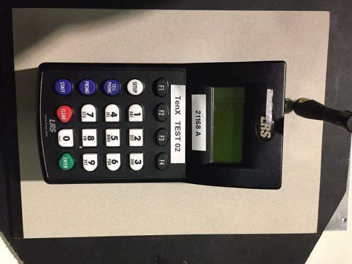
2AB6OTX7471
Mar 11, 2020Paging transmitter
Equipment Class
TNB - Licensed Non-Broadcast Station Transmitter
2AB6OTX7470
Apr 28, 2015Paging Transmitter for restaurant seating
Equipment Class
TNB - Licensed Non-Broadcast Station Transmitter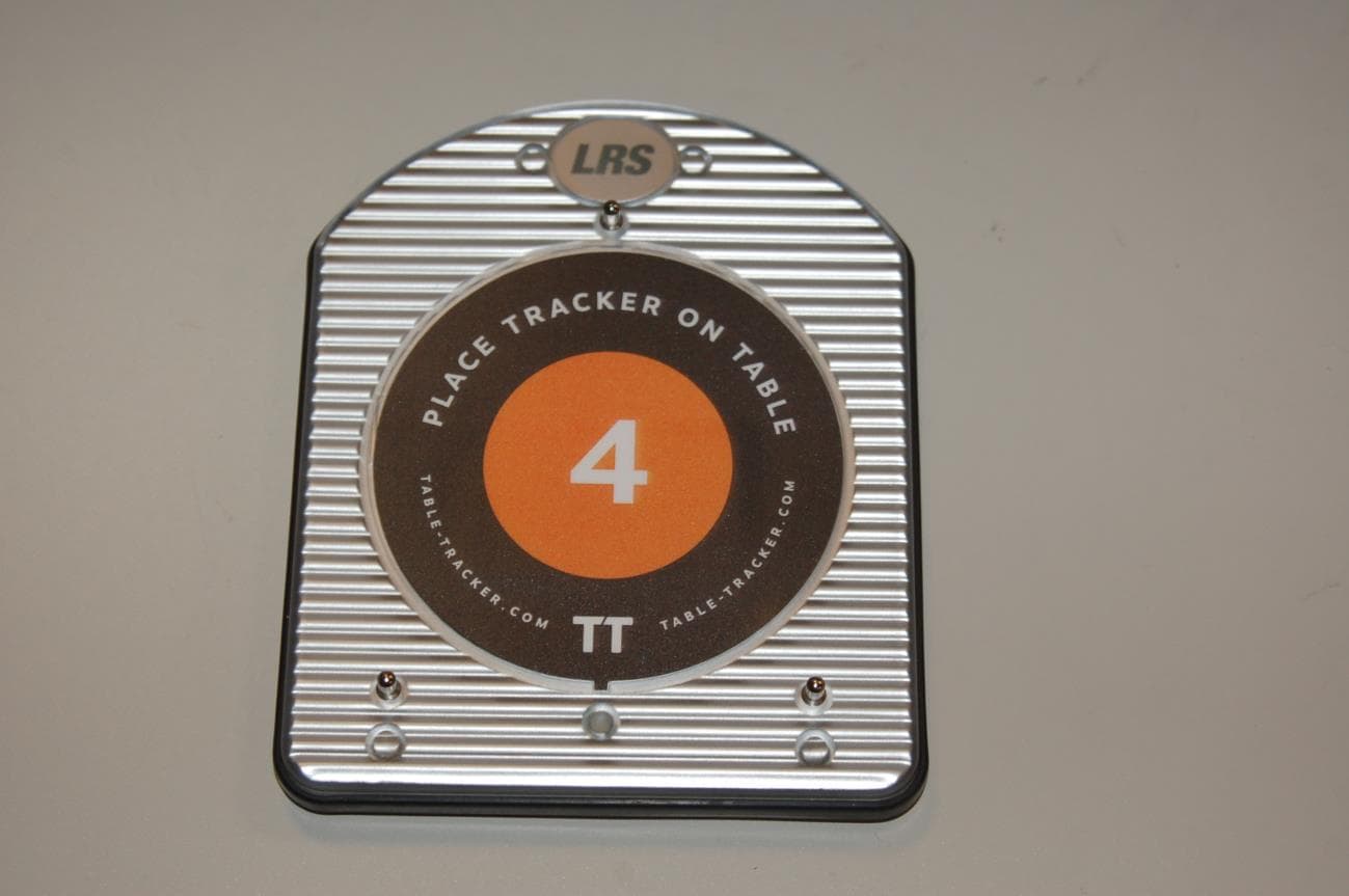
2AB6OTRACKER
Feb 23, 2015Table-Tracking Paging Receiver
Equipment Class
DXX - Part 15 Low Power Communication Device Transmitter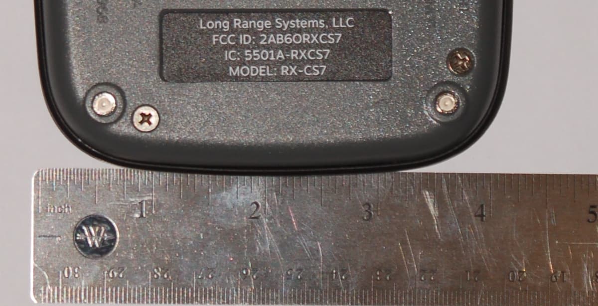
2AB6ORXCS7
Feb 12, 2015Paging Receiver
Equipment Class
DSC - Part 15 Security/Remote Control Transmitter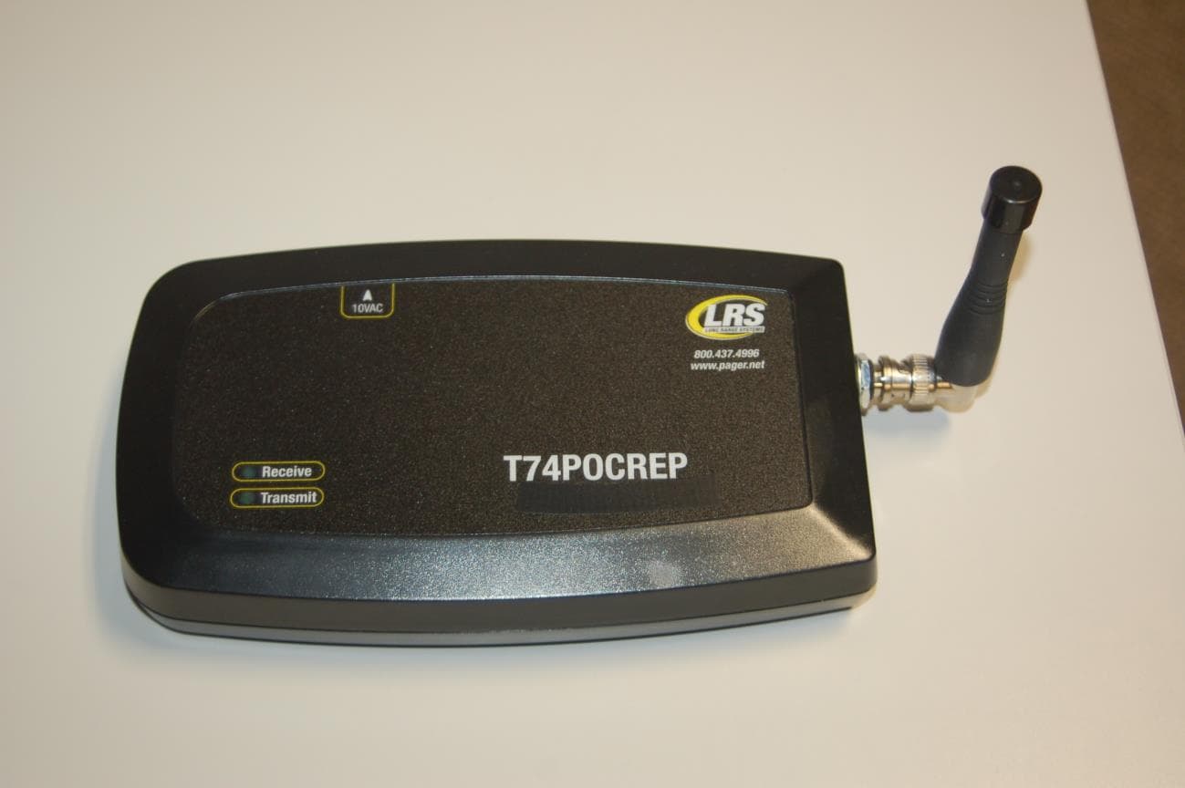
2AB6OTR7400
Sep 17, 2014Short range paging system transmitter
Equipment Class
TNB - Licensed Non-Broadcast Station Transmitter