2AB6OTRACKERTable-Tracking Paging Receiver
Long Range Solutions, LLC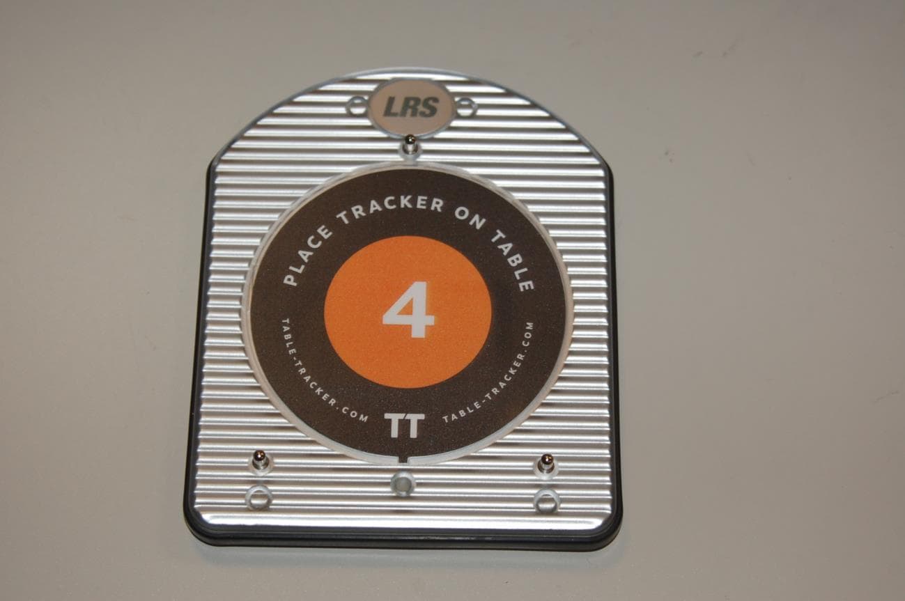
Click to zoom
Application Details
- Equipment Class
- DXX - Part 15 Low Power Communication Device Transmitter
- Date of Grant
- Feb 23, 2015
- Application Purpose
- Original Equipment
- Date of Application
- Feb 23, 2015
- Equipment Note
- Table-Tracking Paging Receiver
- Frequency Range
- 13.56000000 - 13.56000000
- Company
- Long Range Solutions, LLC
- Country
- United States
Documents & Files
Document Text
Text extracted from the exhibit documents filed with the FCC. Open a document above to read the original.
Users Manual
Installation, Warranty and Service Information Long Range Systems, Inc. 4550 Excel Parkway, Suite 200 Addison, TX 75001 800.437.4996 • www.pager.net Table Tracker IMPLEMENTATION GUIDE Table Tracker Implementation Guide Congratulations! You’ve just had the new Table Tracker system by LRS installed in your restaurant. But, now what? How do you use the system? What do you need to know? What does your staff need to know? What do your customers need to know? Well, good news, this implementation guide will answer these questions a nd more. Installation Installers have setup your system and it’s ready to use. There’s nothing additional that you need to install. (Do they need to setup benchmark times or is that already done?) Let’s go over a basic “How it works” so you’ll understand the system before we get into further details. How it works: 1. When a guest places an order, they receive a Table Tracker 2. The guest determines where they will sit and places the Table Tracker on their Table 3. The Table Tracker reads the table number and transmits it back to the display located in the expedite area 4. When the order is ready, the food runner or expediter will reference the display to determine which table to deliver the food 5. The food runner delivers the food and collects the Table Tracker 6. The food runner places the Table tracker on the clearing unit which removes the order from the display We’ve broken down the guide into three sections 1. Order Counter 2. Expedite Area 3. Reporting I. Order Counter Located at the Order Counter/cash register are the Table Trackers which are stacked on the charger. These sit next to a separate “Starter Unit”. 1. A customer places an order 2. The cashier enters the order in your point of sale (POS) system. Each Table Tracker has a unique number on it’s label. This number becomes the order number and is entered into the POS system as such. 3. When the transaction is complete (and not before), the cashier touches the Table Tracker to the Green Starter Unit (the table tracker will vibrate to indicate that it’s been read) and hands the Tracker to the customer with the receipt. Note: In order to receive the most accurate order delivery times in your reports, the Table Tracker shouldn’t be touched to the Starter Unit until the transaction is complete. 4. The cashier should inform the customer to place the Tracker on their table. 5. Repeat these steps for each order Long Range Systems 1 Table Tracker User Manual Long Range Systems 2 Table Tracker User Manual II. Expedite Area In the order expedite area you’ll have an touch screen order display that shows all active orders you’ll also have a laminated table layout. Food runners will reference the the table layout and should commit it to memory. They will be able to deliver orders much quicker when they’ve memorized the layout. 1. When a Table Tracker is placed on the starter unit, it appears on the display and a timer is begun. The table number will not appear until the customer has placed the Tracker on their table. 2. As orders are ready for delivery, food runners must reference the display screen and the laminated table layout to determine where to deliver the order 3. Food runner delivers order to the appropriate table and collects the table tracker 4. Food runner then returns the Tracker to the Clearing Unit located at the expedite area (the optional portable clearing unit which is carried in their pocket may also be used) 5. Once the Tracker has been cleared, stack the units near the expedite area. However, take care to make sure the stack is a minimum of 6” from the clearing unit. Failure to do so will create interference with the system that may cause subpar performance 6. As the stack of cleared Table Trackers grows, return them periodically to the charger near the cash register for re-use. Order colors and what they mean: When a Table Tracker is touched to the starter unit, a timer is started for that order and it will appear on the order display located in the expedite area. There are three colors that help you keep track of orders and where their times are in reference to your benchmark times. The benchmark times may be adjusted to your operation. See the user manual for assistance. When an order is touched to the starter unit, it will appear in green until the first benchmark is reached. Green:order time has begun and is within the benchmark time Yellow:order has reached the intermediate benchmark and is approaching the final benchmark time, you should take notice and necessary actions to complete the order. Red: order has exceeded the final benchmark time, action should be taken to get the order to the guest ASAP III. Reporting Reporting gives you valuable insight into the historical performance of your staff by giving you a variety of reports that can be configured to specific date ranges. Need a list of reports with descriptions and uses: Summary? Detailed summary? FEDERAL COMMUNICATIONS COMMISSION INTERFERENCE STATEMENT This equipment has been tested and found to comply with the limits for a Class B digital device, pursuant to part 15 of the FCC Rules. These limits are designed to provide reasonable protection against harmful inter- ference in a residential installation. This equipment generates, uses and can radiate radio frequency energy and, if not installed and used in accordance with the instructions, may cause harmful interference to radio c ommunications. However, there is no guarantee that interference will not occur in a particular installation. If this equipment does cause harmful interference to radio or television reception, which can be determined by turning the equipment off and on, the user is encouraged to try to correct the interference by one or more of the following measures: -Reorient or relocate the receiving antenna. -Increase the separation between the equipment and receiver. -Connect the equipment into an outlet on a circuit different from that to which the receiver is connect…
Text truncated - open the document above for the full version.
RF Exposure Info
16693 Exposure Supplemental Report Rev 01 Page 1 of 3 Professional Testing (EMI) Inc. 1601 North A.W. Grimes Blvd., Suite B Round Rock, TX 78665 e-mail: [email protected] (512) 244-3371 Fax: (512) 244-1846 1.0 Maximum Permissible Exposure Evaluation (Supplements the test report.) The measured power is considered for the intended use of the device and resulting RF exposure to the user. 1.2 Criteria Section Reference Date KDB 447498 D01 Mobile Portable RF Exposure v05r01 // RSS‐102 Issue 4 March 2010, Notice 2013 DRS0911 2015‐02‐24 1.3 Procedure Using measurement of peak power and considering the intended application, determine the permissible exposure level, applicability of exclusion, or whether additional exposure tests (SAR) are indicated. When applicable justify conclusion for selected exposure level and separation distance. 1.4 Power to Exposure Calculation For 2.4 GHz radio power is determined by conducted measurement. For RFID radio power is determined from the measured field strength and with antenna gain included by default. Due to low fundamental power the source duty cycle was not evaluated for either radio. SAR exemption method was applied for 20 mm spacing. Table 1.4.1 Power Calculation for Exposure, 2.4 GHz Radio (Highest frequency 2.480 GHz) Measured Conducted Power mW Calculated Peak EIRP dBm Source Duty Cycle Factor dB Antenna Gain dBi Calculated EIRP dBm EIRP In Linear Terms mW 0.56 ‐2.51 0.0 1.5 ‐1.01 0.8 Table 1.4.2 Power Calculation for Exposure, 13.56 MHz RFID Radio (Highest frequency 13.56 MHz) Measured Field Strength dBμV/m at 1 m (Peak Detection) Field Strength Restated for dBμV/m at 3 m (Peak Detection) Source Duty Cycle Factor dB Calculated Average Power dBμV/m at 3 m EIRP In Linear Terms mW 57.74 48.2 0.0 48.2 0.0000198 16693 Exposure Supplemental Report Rev 01 Page 2 of 3 Professional Testing (EMI) Inc. 1.5 SAR Exemption Calculation – 3.0 Criteria, 2.4 GHz Band Radio Applicable requirement: KDB 447498 Clause 4.3.1 Section 1 Calculation (max power including tune up tolerance = 0.56 mW): [(0.8 mW)/(20 mm)] · [√2.480 (GHz)] = 0.063 0.063 ≤ 3.0 Therefore, the device meets the applicable FCC SAR exemption requirements. This device meets the SAR Evaluation Exemption criteria in RSS-102 Clause 2.5.1, based on the output power being less than 20 mW for general public use (2.2 GHz – 3.0 GHz). 1.6 SAR Exemption Calculation – 13.56 MHz RFID Radio Applicable requirement: KDB 447498 Clause 4.3.1 Section 3 Calculation (max power including tune up tolerance = 0.0000198 mW): Step 1. P mW = 3.0 x d mm / √f = 3.0 x 50 / √0.01356 = 1288.13 mW Step 2. = 1288 mW + [ (5mm - 50mm) x (13.56 / 150) ] mW = 1284 mW Power Threshold for Frequency 100 MHz to 1500 MHz Step 3. = 1284 mW x 0.5 = 642 mW Power Threshold for Frequency < 100 MHz Result. Max Power 0.0000198 mW < 642 mW Power Threshold Therefore, the device meets the applicable FCC SAR exemption requirements. This device meets the SAR Evaluation Exemption criteria in RSS-102 Clause 2.5.1, based on the output power being less than 200 mW for general public use (13.56 MHz). 16693 Exposure Supplemental Report Rev 01 Page 3 of 3 Professional Testing (EMI) Inc. Signed: Eric Lifsey ***
Test Report
1601 North A.W. Grimes Blvd., Suite B Round Rock, TX 78665 e-mail: [email protected] (512) 244-3371 Fax: (512) 244-1846 February 18, 2015 John Weber Long Range Systems, LLC 4550 Excel Parkway Suite 200 Addison TX 75001 Dear John: Thank you for allowing Professional Testing (EMI), Inc. an opportunity to perform testing for Long Range Systems, LLC. Enclosed is the Wireless Certification Report for the TT-SIL-Z pager. This report can be used to demonstrate compliance with wireless regulatory requirements for wireless devices in North America. If you have any questions, please contact me. Sincerely, Jeffrey A. Lenk President Attachment Long Range Systems, LLC Model TT-SIL-Z (RFID Section) 16693 Professional Testing (EMI) Inc. Page 2 of 23 Project 16693-15 TT-SIL-Z Wireless Pager 13.56 MHz RFID Section Wireless Certification Report Prepared for: Long Range Systems, LLC 4550 Excel Parkway Suite 200 Addison TX 75001 By Professional Testing (EMI), Inc. 1601 North A.W. Grimes Blvd., Suite B Round Rock, Texas 78665 February 18, 2015 Reviewed by Written by Larry Finn Chief Technical Officer Eric Lifsey EMC Engineer Long Range Systems, LLC Model TT-SIL-Z (RFID Section) 16693 Professional Testing (EMI) Inc. Page 3 of 23 Revision History Revision Number Description Date 00 Initial Release February 17, 2015 01 Revised/final per reviewer comments. February 18, 2015 Long Range Systems, LLC Model TT-SIL-Z (RFID Section) 16693 Professional Testing (EMI) Inc. Page 4 of 23 Table of Contents Revision History ............................................................................................................................................................. 3 Certificate of Compliance ............................................................................................................................................. 5 1.0 Introduction.......................................................................................................................................................... 6 1.1 Scope ............................................................................................................................................................... 6 1.2 EUT Description ............................................................................................................................................. 6 1.3 EUT Operation ................................................................................................................................................ 6 1.4 Modifications to Equipment ............................................................................................................................ 7 1.5 Test Site .......................................................................................................................................................... 7 1.6 Radiated Measurements .................................................................................................................................. 7 2.0 Applicable Documents and Clauses ..................................................................................................................... 8 3.0 Fundamental Field Strength ................................................................................................................................. 9 3.1 Test Procedure ................................................................................................................................................ 9 3.2 Test Criteria .................................................................................................................................................... 9 3.3 Test Results ..................................................................................................................................................... 9 4.0 RFID Emission Mask ......................................................................................................................................... 10 4.1 Test Procedure .............................................................................................................................................. 10 4.2 Test Criteria .................................................................................................................................................. 10 4.3 Test Results ................................................................................................................................................... 10 5.0 Radiated Spurious Emissions ............................................................................................................................. 11 5.1 Test Procedure .............................................................................................................................................. 11 5.2 Test Criteria .................................................................................................................................................. 11 5.3 Test Results ................................................................................................................................................... 11 6.0 Antenna Construction Requirements ................................................................................................................. 16 6.1 Test Procedure .............................................................................................................................................. 16 6.2 Test Criteria .................................................................................................................................................. 16 6.3 Test Results ................................................................................................................................................... 16 7.0 Occupied Bandwidth ......................................................................................................................................... 17 7.1 Test Procedure .......…
Text truncated - open the document above for the full version.
Test Setup Photos
16693 Setup Photographs Page 1 of 3 ABOVE 30 MHZ SPURIOUS, FRONT VIEW ABOVE 30 MHZ SPURIOUS, BACK VIEW 16693 Setup Photographs Page 2 of 3 BELOW 30 MHZ SPURIOUS PARALLEL BELOW 30 MHZ SPURIOUS PERPENDICULAR 16693 Setup Photographs Page 3 of 3 FUNDAMENTAL POWER AND BANDWIDTH SHOWN IN MAXIMUM OUTPUT ORIENTATION OF EUT AND MEASUREMENT ANTENNA FREQUENCY STABILITY ***
Contact Information
Applicant
Robert Pinell(Chief Officer)
Test Firm
Professional Testing (EMI), Inc.Larry Finn
Technical Specifications
| # | Rule Parts | Frequency Range | Power Output |
|---|---|---|---|
| 1 | 15C | 13.56 MHz - 13.56 MHz | - |
Other Applications from Long Range Solutions, LLC
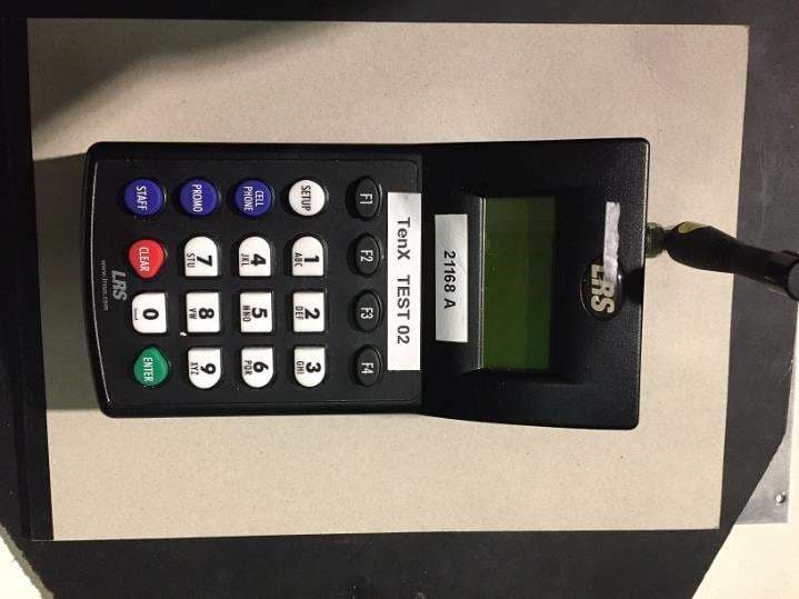
2AB6OTX7471
Mar 11, 2020Paging transmitter
Equipment Class
TNB - Licensed Non-Broadcast Station Transmitter
2AB6OTX7470
Apr 28, 2015Paging Transmitter for restaurant seating
Equipment Class
TNB - Licensed Non-Broadcast Station Transmitter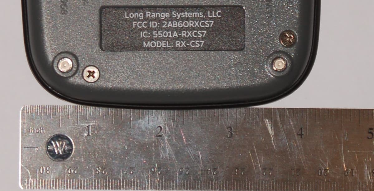
2AB6ORXCS7
Feb 12, 2015Paging Receiver
Equipment Class
DSC - Part 15 Security/Remote Control Transmitter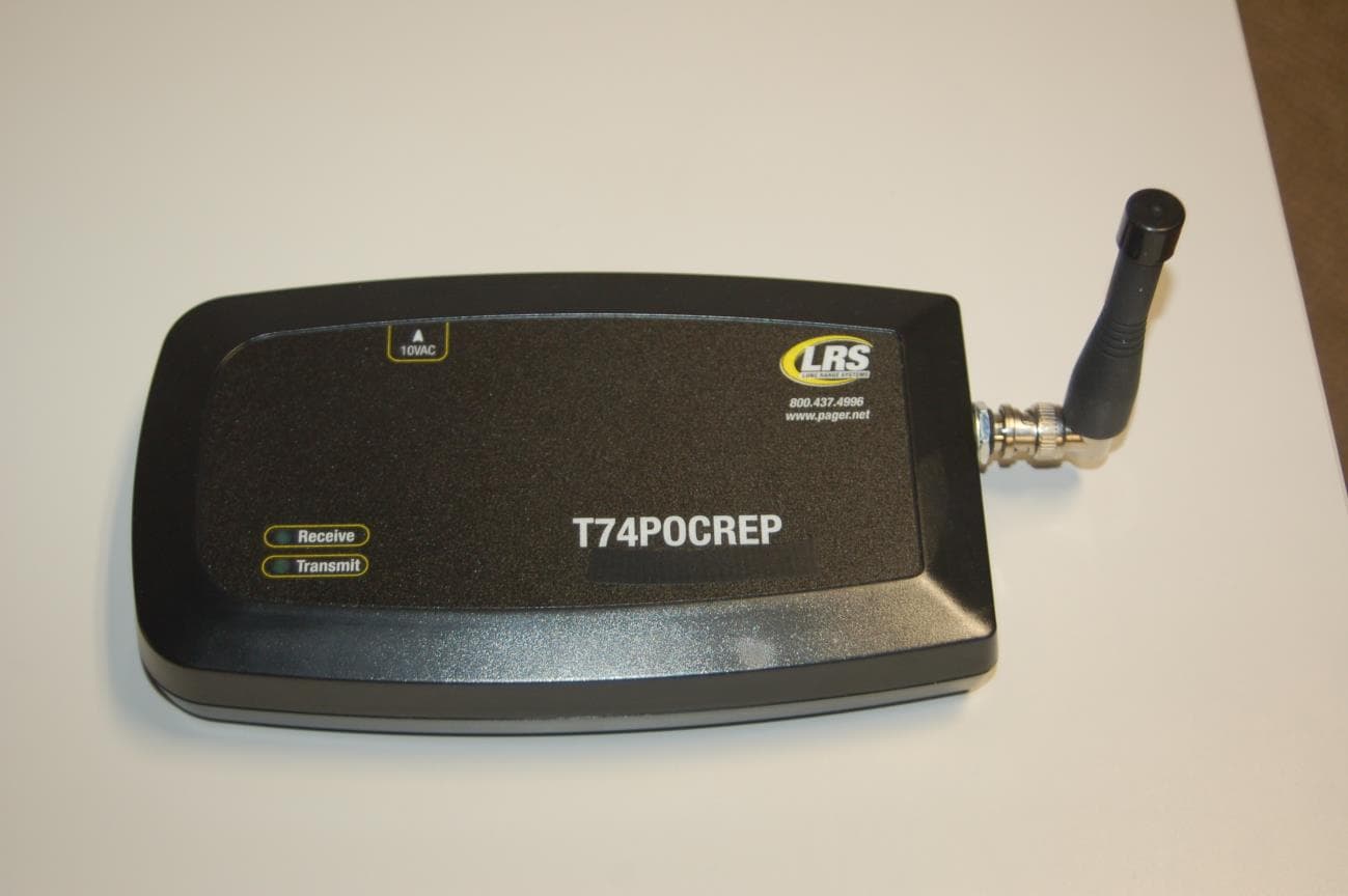
2AB6OTX3B25A
Sep 17, 2014Short range push for service transceiver
Equipment Class
DTS - Digital Transmission System
2AB6OTR7400
Sep 17, 2014Short range paging system transmitter
Equipment Class
TNB - Licensed Non-Broadcast Station Transmitter