2AB6OBUTLERXPShort range paging system transmitter
Long Range Solutions, LLC
Click to zoom
Application Details
- Equipment Class
- TNB - Licensed Non-Broadcast Station Transmitter
- Date of Grant
- May 12, 2014
- Application Purpose
- Original Equipment
- Date of Application
- May 07, 2014
- Equipment Note
- Short range paging system transmitter
- Frequency Range
- 467.75000000 - 467.75000000
- Company
- Long Range Solutions, LLC
- Country
- United States
Documents & Files
Document Text
Text extracted from the exhibit documents filed with the FCC. Open a document above to read the original.
Users Manual
Installation, Warranty and Service Information Long Range Systems, Inc. 4550 Excel Parkway, Suite 200 Addison, TX 75001 800.437.4996 • www.pager.net S E R V I C E w ww.pager.net www.pager.net Butler XP PROGRAMMING GUIDE Table Of Contents Launch Butler XP Application . . . . . . . . . . . . . . . . . . . . . . . . . . . . . . . .4 Read Butler . . . . . . . . . . . . . . . . . . . . . . . . . . . . . . . . . . . . . . . . . . . . . .5 Configuring a Button Butler . . . . . . . . . . . . . . . . . . . . . . . . . . . . . . . . .5 Button Setup . . . . . . . . . . . . . . . . . . . . . . . . . . . . . . . . . . . . . . . . . . . . . . . . .5 System ID . . . . . . . . . . . . . . . . . . . . . . . . . . . . . . . . . . . . . . . . . . . . . . . . . . . .6 Group Paging Enable . . . . . . . . . . . . . . . . . . . . . . . . . . . . . . . . . . . . . . . . . .6 Beep Enable . . . . . . . . . . . . . . . . . . . . . . . . . . . . . . . . . . . . . . . . . . . . . . . . . .7 Secondary Paging . . . . . . . . . . . . . . . . . . . . . . . . . . . . . . . . . . . . . . . . . . . . .7 Cancel Message . . . . . . . . . . . . . . . . . . . . . . . . . . . . . . . . . . . . . . . . . . . . . .8 Low Battery Page . . . . . . . . . . . . . . . . . . . . . . . . . . . . . . . . . . . . . . . . . . . . .8 Repaging . . . . . . . . . . . . . . . . . . . . . . . . . . . . . . . . . . . . . . . . . . . . . . . . . . . .9 Stop Re-Paging . . . . . . . . . . . . . . . . . . . . . . . . . . . . . . . . . . . . . . . . . . . . . . .9 Save a Configuration . . . . . . . . . . . . . . . . . . . . . . . . . . . . . . . . . . . . . .10 Load an Existing Configuration . . . . . . . . . . . . . . . . . . . . . . . . . . . . . .10 Programming Pagers . . . . . . . . . . . . . . . . . . . . . . . . . . . . . . . . . . . . . .11 Group Pagers . . . . . . . . . . . . . . . . . . . . . . . . . . . . . . . . . . . . . . . . . . . . . . . .12 Troubleshooting . . . . . . . . . . . . . . . . . . . . . . . . . . . . . . . . . . . . . . . . .13 Warranty . . . . . . . . . . . . . . . . . . . . . . . . . . . . . . . . . . . . . . . . . . . . . . .14 Long Range Systems1Butler XP Program Guide Launch Butler XP Application Auto Run 1. Insert the CD into the PC drive, program will Auto-run. 2. Follow the Installation Wizard. 3 . Once installation is complete, click on the Windows Start menu. 4. Select All Programs. 5. Select Beach Butler. 6. Select Butler Configurations Utility. 7. The Butler XP configurations screen will display. Manual Install 1. In the event the program does not automatically run on the PC: 2. Insert the CD into the PC drive. 3. Use Windows Explorer to explore the CD drive. 4. Run the Setup program 5. Proceed with the installation wizard 6. Once installation is complete, click on the Windows Start menu. 7. Select All Programs. 8. Select Beach Butler. 9. Select Butler Configurations Utility. 10. The Butler XP configurations screen will display. Long Range Systems2Butler XP Program Guide Read Butler This feature reads the current configuration settings of the Butler. Unit Serial Number and current Firmware Version will display in the bottom right. 1. Connect one end of the USB cable to the PC. 2. Connect the other end of the USB cable to the Butler XP. The USB connection is located in the Butler XP’s battery compartment. (Batteries are not required for programming). 3. Press the Read Butler button. Long Range Systems3Butler XP Program Guide Configuring a Button Butler Note:The Butler XP must be connected to the PC using the USB cable before configuration. . • A configuration can be modified from a previously saved file, or manually created on screen. • For any changes to take affect press the Update • The Update Butler button must be pressed for changes to be applied. Button Setup The Button section is used to set the message sent to the pager when the “Service” button on the Butler XP is pressed. To set a Message: 1. Under PAGER, enter the pager number that the “Service” button will page. 2. Under MESSAGE, enter the message to be sent to the pager. 3. From the MODE drop down box, select an alert mode. Note:Firmware versions prior to 1.11 will only support “Mode” set to DEFAULT Butler ID The Butler ID is used to identify which Butler unit the service request came from. Example:If the Butler ID is “5”, and the message is set to “Service”, then the pager message will dis- play “Service 5”. To set the Butler ID: 1. Enter the Butler ID number 1 to 9999. System ID Note:The System ID should be changed ONLY when interference occurs because of other LRS systems in nearby areas. Default System ID is 0. In the event that more than one LRS system is in close geographical proximity, the system ID can be changed to avoid interference. If the System ID is changed, the System IDs of all pagers also need to be changed (up- dated) to the same System ID. (See Programming Pagers pg. 11) Long Range Systems4Butler XP Program Guide To set System ID: 1. From the System IDdrop down box, select the ID number to use. 2. Click the Update Butlerbutton to save the settings. 3. Reprogram pagers used with the system (refer to Programming Pagers on pg. 10). Group Paging Enable Group Paging allows you to page 2 or more pagers at the same time. You must program the pagers in the same group. (See Programming Pagers on pg. 13) To enable Group Paging: When group paging is enabled, pager numbers 1-99 will be used to page a “group”. (See p. 10 to con- figure Group Paging settings) Beep Enable This feature will enable or disable the Butler from beeping when the “Service” button is pressed, and when the USB connection is made. To set Beep: Under Beep, click on the Enabledcheck box to enable or disable (a check mark indicates beep is en- abled). Long Range Systems5Butler XP Program Guide Secondary Paging The Secondary Paging feature, when enabled, will send a message to a second pager after the third repage cycle. This feature is useful if you want a backup person to resp…
Text truncated - open the document above for the full version.
External Photos
AC/DC Adapter Input Option AC/DC Adapter Input Option 2AA Batteries Option (Battery Cover On) 2AA Batteries Option (Battery Cover Off)
ID Label/Location Info
Long Range Systems LABEL ART AND SPECS 04-28-14 Butler XP FCC Label Placement & Dimensions Label goes here 1.88” x 0.3” FCC ID: 2AB6OBUTLERXP MODEL: TX-175X Material: 2 Mil Digipro DGPWS Polyester white gloss DPM 94 lb, High perf, aggressive permanent adhesive – FLX015412 5 Mil 3M FV02610N Clear Textured Vinyl Laminate Clear Poly liner
Operational Description
FCC ID: 2AB6OTX175X MODEL: TX-175X PRODUCT AND OPERATIONAL DESCRIPTION LONG RANGE SYSTEMS BEACH BUTLER TRANSMITTER 1.0 General Description The Long Range Systems Beach Butler transmitter is a wall or pole mounted paging transmitter used to send commands and data to Long Range Systems staff paging products. The Beach Butler can operate on battery power, 2 AA batteries or connected to a Long Range Systems 120VAC to 5VDC converter. The transmitter is designed for outdoor use, has a single button user interface. It can be configured via a serial port with a single 64 character paging message. A repage interval if needed is also configurable, along with a Manager pager number and manager message To transmit a page, a user presses button labeled service. 2.0 Electronic Description The Beach Butler is comprised of a DC to DC power converter, microcontroller, a FM exciter and encoder chipset set, a low pass filter, and matching network, and a fixed power amplifier. It has a single button user interface. It is configurable via a serial interface inside the battery compartment. Transmitter tuning is performed by an LRS technician with tuning capacitors, and therefore is not configurable or changeable by an end user. Amplifier gain is fixed limiting power output at the antenna port to around 75mW. 3.0 Wireless Description The EUT transmits at a licensed frequency of 467.75 MHz, one channel , FSK modulation. The data is configured as a 64 character message by the end user. It has a transmit range of around ¼ mile. The intended use of the Beach Butler is mounted to a pool side umbrella pole. Mounting hardware is supplied with the installation kit to secure the device to a table, wall, or pole. Optionally a different umbrella mount is also available, and a battery eliminator kit which is inserted in place of the 2 AA batteries, so that the Beach Butler can be powered from an AC wall transformer. It is not designed nor recommended to be handheld. The Beach Butler antenna is wirewound soldered directly to the PCB and completely enclosed inside the plastic housing, with a minimum 1 cm separation distance to any point on the outside.
Operational Description
RUBBER ANTENNA SPECIFICATION S p e c if i ca ti on n o : SA0 2 0 1 5 2 6 CUSTOMER : NEWTEC MODEL: RA-16075(N45-001/A) 1 Application The antenna specified in this specification is applicable for the transceiver. 2 Dimensions As per Drawing No. RA1607501 B001A-N45 attached. 3 Materials As specified in drawing No. RA1607501 B001A-N45 4 Electrical Characteristics i)Resonate Frequency : 450~470 MHz ii)Impedance: 50 ohm Nominal(Depend on available ground plane) iii)Radiation Pattern: Omni Directional iv)Polarization: Vertical v)Standing Wave Ratio (S.W.R) :1.5 or less vi) vii) Insulation resistance : Gain : 0 dBi 500 M ohm at DC 500V 5 Mechanical characteristics: i) The strength of fixing between sleeve and stud shall withstand the following stresses 6 i) Storage Temperature: -30 °C to 80 °C Vertical Direction: 2.0 kgs Rotating Direction: General Characteristics 2.0 kgs Capability Test Report Specification NO.: SA0201526 Model NO.: RA-16075(N45-001/A)
RF Exposure Info
Radiofrequency Radiation Exposure Limits (CFR 47 §1.1310) SAR Exclusion for Long Range Systems ButlerXP The device is to be operated in a pole mounted or similar configuration and not held or carried while in operation. The antenna is internal to the device and separated by at least 10mm from the outside surface of the enclosure where user can be expected to touch with fingers while pushing the “Service” button. Per FCC KDB 447498, the device is exempt from SAR evaluation testing as it meets the exclusion in section 4.3 at a separation distance of 7mm from extremities. The calculation is as follows: 72mW/7mm * √0.468GHz = 7.04, which is less than 10-g extremity SAR limit of 7.5
Test Report
NTS Test Report No. PR027753 File: PR027753 Page 1 Radio Test Report Application for Grant of Equipment Authorization FCC Part 90.217(b) FCC ID: 2AB6OBUTLERXP Model: TX-175X APPLICANT: Long Range Systems, LLC 4550 Excel Parkway, Suite 200 Addison, TX 75001 TEST SITE(S): National Technical Systems - Plano 1701 E Plano Pkwy #150 Plano, TX 75074 REPORT DATE: April 25, 2014 TEST DATES: March 27-31, 2014 TOTAL NUMBER OF PAGES: 23 Prepared By: Approved By: ______________________________ _______________________ Yunus E. Faziloglu Kimberly Zavala Wireless Manager Quality Assurance Manager Reviewed By: ______________________________ John Ngo General Manager This report and the information contained herein represent the results of testing test articles identified and selected by the client performed to specifications and/or procedures selected by the client. National Technical Systems (NTS) makes no representations, expressed or implied, that such testing is adequate (or inadequate) to demonstrate efficiency, performance, reliability, or any other characteristic of the articles being tested, or similar products. This report should not be relied upon as an endorsement or certification by NTS of the equipment tested, nor does it represent any statement whatsoever as to its merchantability or fitness of the test article, or similar products, for a particular purpose. This report shall not be reproduced except in full. NTS Plano -- EMC Department NTS Test Report No. PR027753 Report Date: April 25, 2014 File: PR027753 Page 2 REVISION HISTORY Rev# Date Comments Modified By April 25, 2014 First release NTS Plano -- EMC Department NTS Test Report No. PR027753 Report Date: April 25, 2014 File: PR027753 Page 3 TABLE OF CONTENTS REVISION HISTORY ................................................................................................................................................2 TABLE OF CONTENTS ............................................................................................................................................3 SCOPE..........................................................................................................................................................................4 OBJECTIVE ................................................................................................................................................................5 STATEMENT OF COMPLIANCE ...........................................................................................................................5 DEVIATIONS FROM THE STANDARDS ..............................................................................................................5 TEST RESULTS SUMMARY....................................................................................................................................6 MEASUREMENT UNCERTAINTIES ....................................................................................................................6 THE MEASUREMENT OF UNCERTAINTY IS NOT INCLUDED WITH THE DATA IN THIS TEST REPORT. .............6 EQUIPMENT UNDER TEST (EUT) DETAILS .....................................................................................................7 RF PORT MEASUREMENT PROCEDURES.........................................................................................................8 OUTPUT POWER....................................................................................................................................................8 BANDWIDTH MEASUREMENTS ........................................................................................................................8 CONDUCTED SPURIOUS EMISSIONS ................................................................................................................8 TRANSMITTER MASK MEASUREMENTS .........................................................................................................9 FREQUENCY STABILITY .....................................................................................................................................9 INSTRUMENTATION ............................................................................................................................................9 FILTERS/ATTENUATORS.....................................................................................................................................9 SAMPLE CALCULATIONS....................................................................................................................................10 SAMPLE CALCULATIONS - CONDUCTED SPURIOUS EMISSIONS ............................................................10 APPENDIX A TEST DATA .....................................................................................................................................11 END OF REPORT.....................................................................................................................................................23 NTS Plano -- EMC Department NTS Test Report No. PR027753 Report Date: April 25, 2014 File: PR027753 Page 4 SCOPE An electromagnetic emissions test has been performed on the Long Range Systems Model TX-175X, pursuant to the following rules: FCC Part 90.217 Conducted and radiated emissions data has been collected; reduced and analyzed within this report in accordance with measurement guidelines set forth in the following reference standards and as outlined in the following standards: TIA-603-C FCC Licensed Radio Measurement Guidance KDB 971168 Final system data was gathered in a mode that tended to maximize emissions by varying orientation of EUT, orientation of power and I/O cabling, antenna search height and antenna polarization. Every practical effort was made to perform an impartial test using appropriate test equipment of known calibration. All pertinent factors have been applied to reach the determination of compliance. NTS Plano -- EMC Department NTS Test Report No.…
Text truncated - open the document above for the full version.
Contact Information
Applicant
Robert Pinell(Chief Officer)
Test Firm
National Technical Systems (NTS)Kimberly Zavala
Technical Specifications
| # | Rule Parts | Frequency Range | Power Output | Emission | Tolerance |
|---|---|---|---|---|---|
| 1 | 90.217(b) | 467.75 MHz - 467.75 MHz | 72.00 mW | 10K2F1D | 10.0000000000 ppm |
Other Applications from Long Range Solutions, LLC
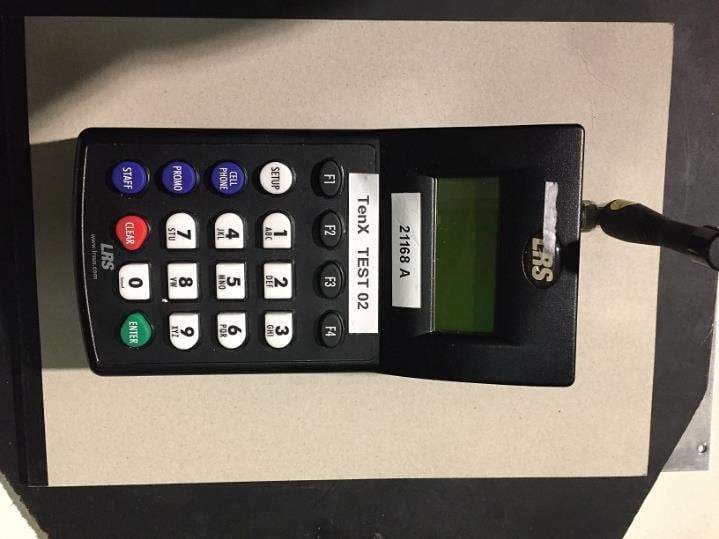
2AB6OTX7471
Mar 11, 2020Paging transmitter
Equipment Class
TNB - Licensed Non-Broadcast Station Transmitter
2AB6OTX7470
Apr 28, 2015Paging Transmitter for restaurant seating
Equipment Class
TNB - Licensed Non-Broadcast Station Transmitter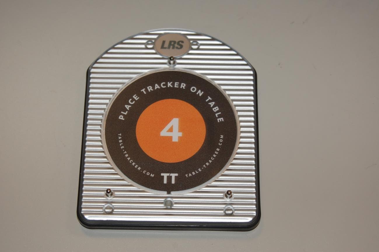
2AB6OTRACKER
Feb 23, 2015Table-Tracking Paging Receiver
Equipment Class
DXX - Part 15 Low Power Communication Device Transmitter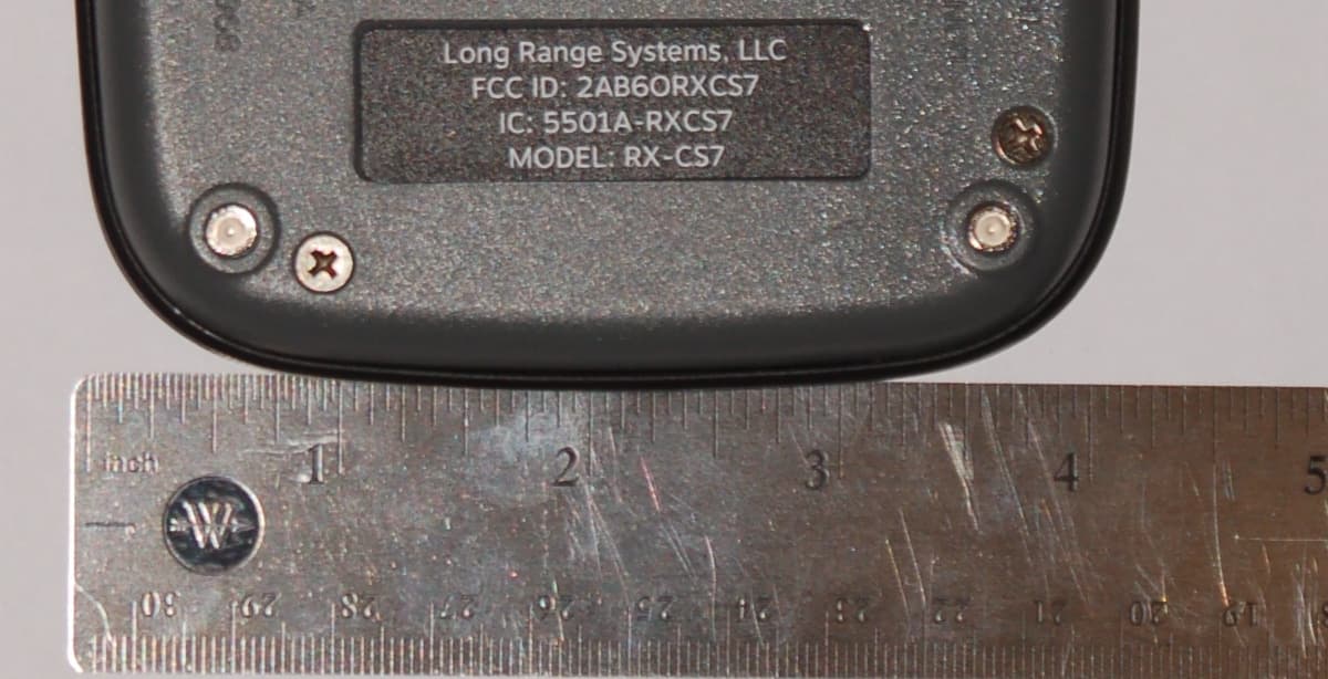
2AB6ORXCS7
Feb 12, 2015Paging Receiver
Equipment Class
DSC - Part 15 Security/Remote Control Transmitter
2AB6OTX3B25A
Sep 17, 2014Short range push for service transceiver
Equipment Class
DTS - Digital Transmission System