2AB6OTR7400Short range paging system transmitter
Long Range Solutions, LLC
Click to zoom
Application Details
- Equipment Class
- TNB - Licensed Non-Broadcast Station Transmitter
- Date of Grant
- Sep 17, 2014
- Application Purpose
- Original Equipment
- Date of Application
- Sep 17, 2014
- Equipment Note
- Short range paging system transmitter
- Frequency Range
- 467.75000000 - 467.75000000
- Company
- Long Range Solutions, LLC
- Country
- United States
Documents & Files
Document Text
Text extracted from the exhibit documents filed with the FCC. Open a document above to read the original.
Users Manual
TR-7400 Description The TR-7400 is designed to booster a transmitter’s signal and “retransmit” the same signal. The unit comes with the following items: • The main unit • 1 right angle antenna • 12-Volt power supply Connecting the Antenna The 3” right angle antenna should be placed on the silver barrel on the side of the main unit, twisted and locked into place (see picture) Long Range Systems1TR-7400 Quick Guide TR-7400 Transmitter- Receiver Paging Transmitter Repeater System QUICK SETUP & OPERATION T r a n s m i t P o w e r 9 V A C 8 0 0 . 4 3 7 . 4 9 9 6 w w w . p a g e r . n e t CONDOR C L A S S 2 T R A N S F O R M E R ( 4 0 8 ) 7 4 5 - 7 1 4 1 I N P U T : A C 1 2 O V 6 0 H z 1 9 w O U T P U T : A C 9 V 1 8 0 0 m A P / N : A 9 1 A 8 R o H S U U L L LISTED C M O D E L : 4 8 A - 9 - 1 8 0 0 E I A 3 6 3 0 6 3 5 S M A D E I N C H I N A AC Power Outlet 10V Power Adapter Antenna Main Unit Positioning and Installing the Booster Note:The best place to mount your Booster is on a ceiling or wall that is very high. The idea is to get the signal as high as possible so it “umbrellas” the guest and thus all pagers can receive it. The booster operates at its best when installed at the “fringe” of your area. This means you should get it as far from the transmitter as possible but still be able to receive the transmitter’s signal. 1. Locate a 110V outlet near the selected installation location. 2. Plug the power adapter into the outlet and into the power connector hole on the side of the unit. 3. Ensure that when power is plugged in, the Red RECEIVE light will blink continu- ously to indicate power is on and the unit is operating. 4. Place the paging transmitter in “Range Test Mode” (see transmitter’s operating in- structions). 5. Ensure the Red TRANSMIT light periodically alternate flashes on about every 5 seconds. • If the periodic TRANSMIT flash does not occur, move the booster unit closer to the transmitter and try again. • Keep moving the booster toward the transmitter until the TRANSMIT flash oc- curs. • After establishing the correct distance, mount the booster as high as possible Normal Range Transmitter TR-7400 Extended Range S E T U P M G R 1 M G R 2 S T A F F C L E A R E N T E R 1 2 3 4 5 6 7 8 9 0 A B C D E F G H I J K L M N O P Q R S T U V W X Y Z [ T 7 4 0 0 A L o n g R a n g e S y s t e m s 8 0 0 . 4 3 7 . 4 9 9 6 F 1 F 2 F 3 F 4 T r a n s m i t P o w e r 9 V A C 8 0 0 . 4 3 7 . 4 9 9 6 w w w . p a g e r . n e t : : Long Range Systems2TR-7400 Quick Guide System Specification Required voltage: One 110V outlet for the pager keypad. Operating Frequency:467.75 MHz Radiated Power <120mW Operating Range:Dependent upon pagers used and topography and environment. Long Range Systems, LLC reserves the right to make changes without further notice to any products herein. Long Range Systems, LLC makes no warranty, representation or guarantee regarding the suitability of its prod- ucts for any particular purpose, nor does Long Range Systems, LLC assume any liability arising out of the appli- cation or use of any product or circuit, and specifically disclaims any and all liability, including without limitation consequential or incidental damages. “Typical” parameters that may be provided in Long Range Systems, LLC data sheets and/or specifications can and do vary in different applications and actual performance may vary over time. All operating parameters, including “Typicals”, must be validated for each customer application by customer’s technical experts. Long Range Systems, LLC products are not designed, intended, or authorized for use as components in systems intended to support or sustain life, or for any other application in which the failure of the Long Range Systems, LLC product could create a situation where personal injury or death may occur. Should Buyer purchase or use Long Range Systems, LLC products for any such unintended or unauthorized ap- plication, Buyer shall indemnify and hold Long Range Systems, LLC and its officers, employees, subsidiaries, af- filiates, and distributors harmless against all claims, costs, damages, and expenses, and reasonable attorney fees arising out of, directly or indirectly, any claim of personal injury or death associated with such unintended or unauthorized use, even if such claim alleges that Long Range Systems, LLC was negligent regarding the design or manufacture of the part, device or system. 1. This device complies with Part 15 of the FCC Rules. Operation is subject to the following two conditions: (1) This device may not cause harmful interference. (2) This device must accept any interference received, including interference that may cause undesired opera- tion. 2. Changes or modifications not expressly approved by the party responsible for compliance could void the user's authority to operate the equipment. RF warning statement: The device has been evaluated to meet general RF exposure requirement of a mobile device. It is designed to operate and should be placed in an area with a minimum separation distance to nearby persons of at least 20 Centimeters. Long Range Systems, LLC 4550 Excel Parkway, Suite 200, Addison, TX 75001 www.pager.net • 214.553.5308 Long Range Systems3TR-7400 Quick Guide XU-0055 061014
ID Label/Location Info
Long Range Systems LABEL ART AND SPECS 06-10-14 TR-7400 FCC Label Placement & Dimensions Label goes here 2.03” x 0.55” Long Range Systems LLC FCC ID: 2AB6OTR7400 MODEL: TR-7400 Material: 2 Mil Digipro DGPWS Polyester white gloss DPM 94 lb, High perf, aggressive permanent adhesive – FLX015412 5 Mil 3M FV02610N Clear Textured Vinyl Laminate Clear Poly liner
Operational Description
RUBBER ANTENNA SPECIFICATION S p e c if i ca ti on n o : SA0 2 0 1 5 2 6 CUSTOMER : NEWTEC MODEL: RA-16075(N45-001/A) 1 Application The antenna specified in this specification is applicable for the transceiver. 2 Dimensions As per Drawing No. RA1607501 B001A-N45 attached. 3 Materials As specified in drawing No. RA1607501 B001A-N45 4 Electrical Characteristics i) Resonate Frequency : 450~470 MHz ii) Impedance : 50 ohm Nominal(Depend on available ground plane) iii) Radiation Pattern : Omni Directional iv) Polarization : Vertical v) Standing Wave Ratio (S.W.R) : 1.5 or less vi) Insulation resistance : 500 M ohm at DC 500V 5 Mechanical characteristics: i) The strength of fixing between sleeve and stud shall withstand the following stresses 6 i) Storage Temperature : -30°C to 80 °C Vertical Direction: 2.0 kgs Rotating Direction: General Characteristics 2.0 kgs Capability Test Report Specification NO.: SA0201526 Model NO.: RA-16075(N45-001/A)
Operational Description
FCC ID: 2AB6OTR7400 Product and Operational Description TR-7400 Long Range Systems, LLC 1. General Description The Long Range Systems, LLC (LRS), TR-7400 is a POCSAG transceiver. It will only receive LRS encoded POCSAG transmissions decode and re-broadcast the same transmission. It is a mobile station transmitter requiring 12Vdc input power. It does not have a user interface. It is designed to be placed on the outer edges of the LRS radio range where signals have been attenuated by interior walls or floors, receive and then retransmit the same signal in order to recover the range of the originating transmitter. It uses 2 separate antennas for operation. The transmitting antenna is a 3” off-the-shelf 400MHz rubber duck model antenna connected externally to the unit via a BNC connector. The receiver antenna is a PCB trace antenna etched on a modular receiver board. 2. Electronic Description The two major components of the TR-7400 are a transmitter section and a receiver section. The main transmitter board consists of a DC-DC power converter, micro-controller, frequency synthesizer, and power amplifier. Input power is supplied by a 120VAC to 12Vdc 4 amp power supply. A DC-DC converter steps down the voltage from 12Vdc to 3.3Vdc which is used by all circuit components including the output power amplifier. The receiver module is a plugin daughter board. It consists of a PCB antenna, filter, down converter, demodulator, and a decoder. When an LRS message is received, it is decoded and sent to the micro-controller via a SPI bus, where it is CRC checked and validated according to LRS messaging protocol, then manchester encoded, modulated, upconverted to the transmit frequency, and amplified out an external antenna at no more than 120mW. 3. Wireless Description Receives and re-transmits an LRS over-the-air message at a licensed frequency of 467.75 MHz, one channel, FSK modulation. Bit rate is 1200 Baud. Only LRS formatted data is received and retransmitted. There are no user input or configuration parameters.
RF Exposure Info
Radiofrequency Radiation Exposure Limits (CFR 47 §1.1310) Prediction of MPE at a given distance can be calculated by the equation from FCC OET Bulletin 65 Edition 97-01, August 1997 where: S = power density (in appropriate units, e.g. mW/cm2) P = power input to the antenna (in appropriate units, e.g., mW) G = power gain of the antenna in the direction of interest relative to an isotropic radiator R = distance to the center of radiation of the antenna (appropriate units, e.g., cm) For this device, Peak output power at the antenna terminal = 20.68dBm Antenna gain = 2dBi Frequency = 467.75MHz Prediction distance = 20cm Limit = 467.75/1500 = 0.312 (per CFR 47 §1.1310) By solving the equation for this device, Power density at 20cm = 0.037mW/cm2 Therefore device complies with FCC RF radiation exposure limits for general population in mobile exposure category (distance > 20cm). 2 4R PG S π =
Test Report
NTS Test Report No. PR027012 rev2 File: PR027012 Page 1 Radio Test Report Application for Grant of Equipment Authorization FCC Part 90.217(b) FCC ID: 2AB6OTR7400 Model: TR-7400 APPLICANT: Long Range Systems, LLC 4550 Excel Parkway, Suite 200 Addison, TX 75001 TEST SITE(S): National Technical Systems - Plano 1701 E. Plano Pkwy #150 Plano, TX 75074 REPORT DATE: Sep 2 2014 TEST DATES: April 1 2014, April 28 2014, August 28 2014 TOTAL NUMBER OF PAGES: 25 Prepared By: Approved By: ______________________________ _______________________ Yunus E. Faziloglu Kimberly Zavala Wireless Manager Quality Assurance Manager Reviewed By: ______________________________ John Ngo General Manager This report and the information contained herein represent the results of testing test articles identified and selected by the client performed to specifications and/or procedures selected by the client. National Technical Systems (NTS) makes no representations, expressed or implied, that such testing is adequate (or inadequate) to demonstrate efficiency, performance, reliability, or any other characteristic of the articles being tested, or similar products. This report should not be relied upon as an endorsement or certification by NTS of the equipment tested, nor does it represent any statement whatsoever as to its merchantability or fitness of the test article, or similar products, for a particular purpose. This report shall not be reproduced except in full. NTS Plano -- EMC Department NTS Test Report No. PR027012 rev2 Report Date: Sep 2, 2014 File: PR027012 Page 2 REVISION HISTORY Rev# Date Comments Modified By 0 May 8, 2014 First Release YF 1 Aug 20, 2014 FCC ID and Model change per client’s request YF 2 Sep 2, 2014 To address TCB comments YF NTS Plano -- EMC Department NTS Test Report No. PR027012 rev2 Report Date: Sep 2, 2014 File: PR027012 Page 3 TABLE OF CONTENTS REVISION HISTORY ................................................................................................................................................ 2 TABLE OF CONTENTS ............................................................................................................................................ 3 SCOPE .......................................................................................................................................................................... 4 OBJECTIVE ................................................................................................................................................................ 5 STATEMENT OF COMPLIANCE ........................................................................................................................... 5 DEVIATIONS FROM THE STANDARDS .............................................................................................................. 5 TEST RESULTS SUMMARY .................................................................................................................................... 6 MEASUREMENT UNCERTAINTIES .................................................................................................................... 6 THE MEASUREMENT OF UNCERTAINTY IS NOT INCLUDED WITH THE DATA IN THIS TEST REPORT. ............. 6 EQUIPMENT UNDER TEST (EUT) DETAILS ..................................................................................................... 7 RF PORT MEASUREMENT PROCEDURES ......................................................................................................... 8 OUTPUT POWER .................................................................................................................................................... 8 BANDWIDTH MEASUREMENTS ........................................................................................................................ 8 CONDUCTED SPURIOUS EMISSIONS ................................................................................................................ 8 TRANSMITTER MASK MEASUREMENTS ......................................................................................................... 9 FREQUENCY STABILITY ..................................................................................................................................... 9 INSTRUMENTATION ............................................................................................................................................ 9 FILTERS/ATTENUATORS ..................................................................................................................................... 9 SAMPLE CALCULATIONS .................................................................................................................................... 10 SAMPLE CALCULATIONS - CONDUCTED SPURIOUS EMISSIONS ............................................................ 10 APPENDIX A TEST DATA ..................................................................................................................................... 11 END OF REPORT ..................................................................................................................................................... 25 NTS Plano -- EMC Department NTS Test Report No. PR027012 rev2 Report Date: Sep 2, 2014 File: PR027012 Page 4 SCOPE An electromagnetic emissions test has been performed on the Long Range Systems Model TR-7400, pursuant to the following rules: FCC Part 90.217 Conducted and radiated emissions data has been collected; reduced and analyzed within this report in accordance with measurement guidelines set forth in the following reference standards: TIA-603-C FCC Licensed Radio Measurement Guidance KDB 971168 Final system data was gathered in a mode that tended to maximize emissions by varying orientation of EUT, orientation of power and I/O cabling, antenna search height and antenna polarization when applicable. Every practical effort was made to perform an impartial test using appropriate test equipment of known ca…
Text truncated - open the document above for the full version.
Contact Information
Applicant
Robert Pinell(Chief Officer)
Test Firm
National Technical Systems (NTS)Kimberly Zavala
Technical Specifications
| # | Rule Parts | Frequency Range | Power Output | Emission | Tolerance |
|---|---|---|---|---|---|
| 1 | 90.217(b) | 467.75 MHz - 467.75 MHz | 117.00 mW | 11K5F1D | 10.0000000000 ppm |
Other Applications from Long Range Solutions, LLC
2AB6OTX7471
Mar 11, 2020Paging transmitter
Equipment Class
TNB - Licensed Non-Broadcast Station Transmitter
2AB6OTX7470
Apr 28, 2015Paging Transmitter for restaurant seating
Equipment Class
TNB - Licensed Non-Broadcast Station Transmitter
2AB6OTRACKER
Feb 23, 2015Table-Tracking Paging Receiver
Equipment Class
DXX - Part 15 Low Power Communication Device Transmitter
2AB6ORXCS7
Feb 12, 2015Paging Receiver
Equipment Class
DSC - Part 15 Security/Remote Control Transmitter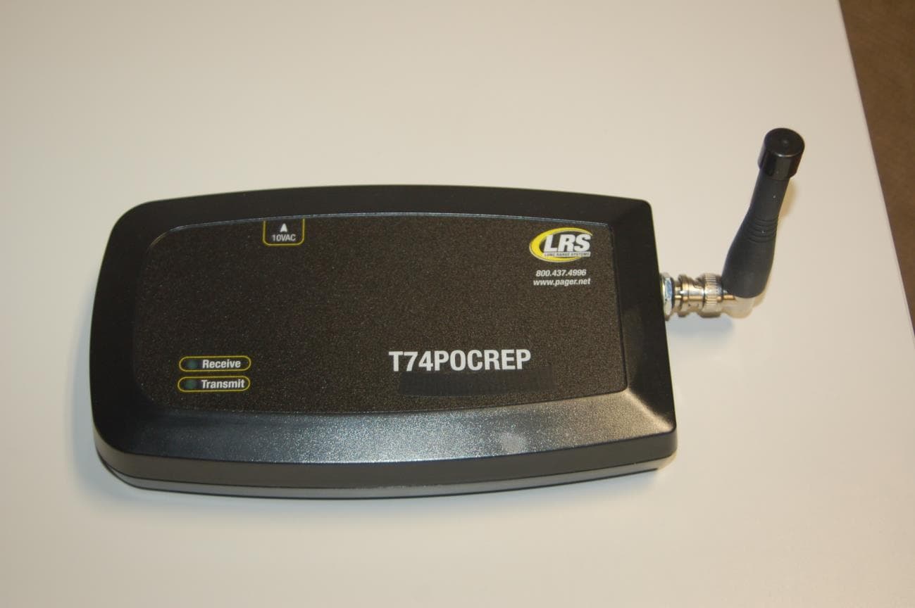
2AB6OTX3B25A
Sep 17, 2014Short range push for service transceiver
Equipment Class
DTS - Digital Transmission System