2AB6OTX1605Short range paging system transmitter
Long Range Solutions, LLC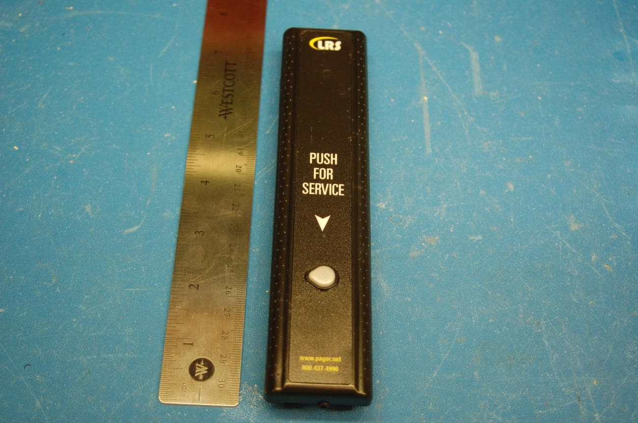
Click to zoom
Application Details
- Equipment Class
- TNB - Licensed Non-Broadcast Station Transmitter
- Date of Grant
- Aug 13, 2014
- Application Purpose
- Original Equipment
- Date of Application
- Aug 13, 2014
- Equipment Note
- Short range paging system transmitter
- Frequency Range
- 467.75000000 - 467.75000000
- Company
- Long Range Solutions, LLC
- Country
- United States
Documents & Files
Document Text
Text extracted from the exhibit documents filed with the FCC. Open a document above to read the original.
Users Manual
Each button on the one or five button Butler II can be programmed to send a unique message to separate pagers or group of pagers. Both the five-button and one-button models can also send a specific message for an external switch or sensor. Installation To put the Butler II in operation: Note:If your Butler II is not already programmed, refer to the programming guide first. 1. Install the 3-batteries in the butler (note the + end) 2. Locate the mounting bracket where it is to be used. (use screws, straps or velcro) 3. Install the batteries. 4. Position the unit into the notches in the mounting bracket and press until latch en- gages. 5. Connect an external sensor (if used) 6. Turn on the pager (refer to the pager booklet). 7. Press the button(s) to test the pager. Normal Operation 1. The indicator light will be faintly blinking 2. Press a button, the indicator light will flash and the pager will receive the message. 3. For external contacts, enable the contact and the pager will receive the message. Advanced Feature Operation Enabling the following features require the programming kit. Instructions for this kit are contained in the Help file. Auto Off/On The Butler II can be set to automatically turn off or on at pre-selected times of the day. Page Acknowledge The Confirmation button will send a message indicating the time between a button press Long Range Systems1Butler II Quick Guide Butler II Five and One Button Paging System QUICK SETUP & OPERATION (or other input) and staff response. Low Battery Page The Butler II can send a low battery message when batteries are low. Lockout The alarm input can be locked out (disabled) for a period of time. This allows staff to pass through monitored areas without setting off alarms. • The staff member presses Confirmation button simultaneously, • Then enters a 3-digit disable code. • The alarm is disabled for a selected time and will reinitiate when the alarm con- tacts are restored. Long Range Systems2Butler II Quick Guide Latch Tie Wraps Screws Velcro Battery + End Battery Door Mounting Notches External Input Confirmation Button Buttons Indicator Light Confirmation Button Paging Buttons Indicator Light Confirmation Button Paging Buttons Push For Service Five ButtonOne Button WARRANTY Long Range Systems Inc warrants this product against any defects that are due to faulty material or workmanship for a two- year period after the original date of consumer purchase. The warranty does not include damage to the product resulting from accident, misuse, improper electrical connection, or failure to charge the product within 30 days of receipt. Recharge- a ble pagers are required to stay on charge while not in use. Rechargeable pagers that are left off of charge for longer than 30 days will have a negative impact on the life of the batteries requiring them to be replaced thus voiding the war- ranty.If this product should become defective within the warranty period, we will repair or replace it with an equivalent prod- uct, free of charge. LRS will return your product via UPS ground shipping. All warranty claims must be initiated through our customer service department: Long Range Systems, LLC, 4550 Excel Pkwy, Suite 200, Addison, TX 75001. No return or replacement can be received without prior authorization and the proper RMA Number posted to the outside of the shipping container. This warranty gives you specific legal rights and you may also have rights that vary from state to state. Copyright © October 2004, Long Range Systems, LLC All Rights Reserved This document contains proprietary information of Long Range Systems, LLC (LRS) and is intended for use only by it’s employees or customers. None of the material contained herein may be copied, reproduced, republished, downloaded, displayed, posted, or transmitted in any form or by any means, including but not limited to, electronic, mechanical, photocopying, recording, or oth- erwise without the prior written permission of LRS. Additional copies of this manual may be obtained by contacting LRS. Screen displays, keyboard layouts, hardware descriptions, or software are proprietary to LRS and are subject to copyright and other intellectual property rights of LRS and shall be treated in accordance with the previous paragraph. All attempts have been made to make the information in this document complete and accurate. LRS is not responsible for any direct or indirect damages or loss of business resulting from inaccuracies or omissions. Specifications and other information contained within this document are subject to change without notice. Long Range Systems, LLC reserves the right to make changes without further notice to any products herein. Long Range Sys- tems, LLC makes no warranty, representation or guarantee regarding the suitability of its products for any particular purpose, nor does Long Range Systems, LLC assume any liability arising out of the application or use of any product or circuit, and specifically disclaims any and all liability, including without limitation consequential or incidental damages. “Typical” parame- ters that may be provided in Long Range Systems, LLC data sheets and/or specifications can and do vary in different applica- tions and actual performance may vary over time. All operating parameters, including “Typicals”, must be validated for each customer application by customer’s technical experts. Long Range Systems, LLC products are not designed, intended, or authorized for use as components in systems intended to support or sustain life, or for any other application in which the failure of the Long Range Systems, LLC product could create a situation where personal injury or death may occur. Should Buyer purchase or use Long Range Systems, LLC products for any such unintended or unauthorized application, Buyer shall indemnify and hold Long Range Systems, LLC and its officers, employees, subsidiaries, affiliates, and distributors harmless against all claims, costs, damages, and ex…
Text truncated - open the document above for the full version.
Cover Letter(s)
4550 Excel Parkway, Suite 200 | Addison, TX 75001 | 800.437.4996 | www.pager.net July 8, 2014 Nemko Canada Inc. 303 River Road Ottawa, Ontario, Canada K1V 1H2 FCC ID: 2AB6OTX1605 Product Name: TX-1605-5 and TX-1605-1 Attn: Director of Certification Explanation of Dual Model Transmitters. Transmitter model numbers TX-1605-1 and TX-1605-5 use a single PCB with identical components, identical antennas, firmware, and Tuning and Testing procedures. The difference between the two transmitter models is seen in the figures below. Figure 1 is the TX-1605-5 which allows a user to page up to 5 different pager numbers or send 5 different pre-programmed messages to 1 pager number or various combinations thereof. Figure 2 is the TX-1605-1 which only allow a single button to page a single pager number with a single message. Offering two keypad versions for the same transmitter gives our customers a choice in how they prefer to implement they’re paging application. Regards, Mike Williams LRS Engineer Figure 1 TX-1605-5 Five Button Butler-II 4550 Excel Parkway, Suite 200 | Addison, TX 75001 | 800.437.4996 | www.pager.net Figure 2 1 TX-1605-1 One Button Butler-II
ID Label/Location Info
Long Range Systems LABEL ART AND SPECS 05-01-14 TX-Butler II FCC Label Placement & Dimensions Label goes here FCC ID: 2AB6OTX1605 MODEL: TX-1605-1 and TX-1605-5 Material: 2 Mil Digipro DGPWS Polyester white gloss DPM 94 lb, High perf, aggressive permanent adhesive – FLX015412 5 Mil 3M FV02610N Clear Textured Vinyl Laminate Clear Poly liner
Operational Description
FCC ID: 2AB6OTX1605 MODEL: TX-1605-1 / TX-1605-5 PRODUCT AND OPERATIONAL DESCRIPTION LONG RANGE SYSTEMS BUTLER II TRANSMITTER 1.0 General Description The Long Range Systems Butler II transmitter is a 7” x 1½” x 1” wall mounted paging transmitter used to send commands and data to Long Range Systems staff and guest paging products. The ButlerII is battery powered, requiring 3 AAA batteries. The transmitter is designed for indoor use only. It is configured via a mini-B USB interface and a PC application . Configuration settings include button data, system ID, periodic alarms and timed repaging intervals. There is a button on the side of the transmitter used to cancel a repaging operation. 2.0 Electronic Description The Butler II is comprised of a microcontroller, a FM exciter and encoder chipset set, a low pass filter, matching network, and a power amplifier. Transmitter tuning is performed by an LRS technician with tuning capacitors, and therefore is not configurable or changeable by an end user. Amplifier gain is set during tuning procedure so that power output at the antenna port is around 55mW. 3.0 Wireless Description The EUT transmits at a licensed frequency of 467.75 MHz, one channel , FSK modulation. Pager messages are limited to 64 characters in length. It has a transmit range of around 1/10 mile. A wall mounting plate is supplied in the installation kit. No other options are available. It is not designed nor recommended to be handheld. The Butler II antenna is a 22 awg solid wire soldered directly to the PCB and raised slightly above the PCB, completely enclosed inside the plastic housing. 4.0 Model Description There a 2 different models of Butler II transmitters available. A single button model TX-1605- 1 and a 5 button model TX-1605-5. PCB is identical in both models. Only front face plastic and button membrane is different between the models. Firmware is the same for both models also.
Parts List/Tune Up Info
Butler II Program & Test Page 1 Butler II Program and Test Long Range Systems LLC. 4550 Excel Parkway Suite 200, Addison, TX 75001 1-800-437-4996 Butler II Program & Test Butler II Program & Test Page 2 Items Needed: PC (XP or Vista) USB type A to mini-B cable Atmel FLIP software LRS ButlerII USB Configuration Program Power Supply Spectrum Analyzer Initial SETUP: The ButlerII USB uses the DFU (Device Firmware Update) USB feature to load firmware. This feature is accessed in the boot-loader of the unit and must be entered during a reset of the device. New un-programmed units automatically run the DFU boot- loader. Step 2 describes how to enter the DFU boot-loader if needed. If the PC has previously been setup to run FLIP including the DFU driver has been installed proceed to the section “Programming the Unit”. 1) ONLY IF NEEDED: Install ATMEL FLIP 3.X Software, You can get the software by following this link: http://www.atmel.com/dyn/products/tools_card.asp?tool_id=3886 Select either the version with or without Java depending on whether you computer already has the Java runtime installed. (suggestion, remove any previous installation of java runtime and install complete programming system (java+FLIP) Follow the directions for installing FLIP as provided 2) ONLY IF NEEDED: Install the Windows DFU driver. Plug in an un- programmed unit to the PC via the USB cable. This will force the DFU boot- loader firmware to run, Windows will detect the new device and prompt for the installation of the appropriate driver. Follow Appendix A to install the appropriate driver. FLIP cannot operate until this driver is installed. This operation will be performed only once for each type of MCU to be programmed or if using a different USB hub on the same PC. Butler II Program & Test Page 3 Programming and Test 1) Connect the USB cable to an un-programmed unit. (If this is the first time to do this on the PC you will need to install the DFU driver, see appendix A for instructions) 2)Using FLIP, load the required firmware hex file from “Mfg/Firmware/ButlerIIUSB/release “ directory and program the unit (see appendix B) 3)The units will begin transmitting a test signal immediately upon initialization allowing adjustment. Power Adjustment Remove the USB connection and connect a DC power supply (minus at J3, plus at J2), note the LED should turn on continuously indicating the unit is transmitting 3.6V, monitor the Power Supply current meter, make sure the voltage does not drop below 3.6V at the PCB terminals, if so increase the DC supply (maximum applied voltage 4.5VDC) a) Adjust R28 potentiometer for current draw of 160-180mA maximum. Corresponds to an RF output power of 75mW and is considered the optimal value. Note: Exceeding this range or going under can drastically affect the battery life and output transmitter power/performance. Frequency Adjustment Setup spectrum analyzer for 400MHz Antenna Input 467.75Mhz center frequency 100KHz span 300Hz Resolution Bandwidth 0 dBm Reference 10 db/div Transmitter output at an approximate distance of 3 feet is shown in diagram below. FSK signal shape of a saddle with peaks around 0dBm and center down 20 dBm from peaks. Signal should be clean with little noise or spikes. *Signal Amplitude is relative to distance to measuring antenna. Tuning center frequency a) Adjust the center frequency with C21 variable cap, monitor with a spectrum analyzer Center Frequency Tolerance +/- 500 Hz Frequency Deviation peaks +/- 4500Hz Butler II Program & Test Page 4 4) Once the unit is ready to be shipped connect the unit to a PC via the USB cable and run the configuration utility, press “Read Butler” to verify communication and permanently disable the transmitter test feature. Below is the correct settings as read. Butler II Program & Test Page 5 Butler II Program & Test Page 6 Retuning In the event of needing to retune a Butler after programming, use the Butler 2 USB Project, with USB Cable. 1) Set Product ID to „0xaa55‟ for Butler 2 and press Set ID (only needs to be done at start of session once) 2) Connect USB Cable to Butler 2 3) Type TX,1, and Send. Butler will now go into TX mode. Butler II Program & Test Page 7 4) Adjust C21 until output is at frequency. 5) Either disconnect USB cable or type TX,0 and Send. Butler II Program & Test Page 8 Appendix A - Installing the DFU Windows Driver If the PC has never before programmed a ButlerIIUSB you will need to load the ATMEL DFU device driver, the PC should already be prompting you for this driver, it is located in the Atmel install directory of the FLIP software under the „usb‟ directory. Just select the „usb‟ directory and allow Windows to install that driver. On this page and those following, are screen shots of the steps involved in setting up the USB DFU driver after the software is first installed. This must be done for FLIP to communicate with the ButlerIIUSB This is the prompt shown for a new unit (never programmed). If the unit has been programmed you will need to manually start the DFU boot-loader. While holding SW1 in, reset the unit by momentarily shorting the middle two pins (across the connector pins 5&6) on J4. Do not let Windows search for the driver, you need to specify the location as shown below. Butler II Program & Test Page 9 Note that the driver is for the DFU (device firmware update), select install from a specific location (ButlerII uses AT90USB64 DFU) Select the location to search for the driver, match this screen and press the Browse button Butler II Program & Test Page 10 The appropriate driver will be found in the installation directory of the FLIP software in the „usb‟ directory, the typical installation is shown below Butler II Program & Test Page 11 Final loading of the USB DFU device driver by Windows. ButlerII will show AT90USB64 After this step, FLIP can be run and configured to program the AT90USB device, see appendix B. Butler II Program & Test Page 12 Appendix B – Configuring FLIP for Programmin…
Text truncated - open the document above for the full version.
RF Exposure Info
Radiofrequency Radiation Exposure Limits (CFR 47 §1.1310) SAR Exclusion for Long Range Systems FCC ID: 2AB6OTX1605 The device is to be operated in a stationary wall mount or table top configuration. The wire antenna is internal to the device. Per FCC KDB 447498, the device is exempt from SAR evaluation testing as it meets the exclusion in section 4.3 at a separation distance of 5mm from extremities. The calculation is as follows: 52mW/5mm * √0.468GHz = 7.11, which is less than 10-g extremity SAR limit of 7.5
Test Report
NTS Test Report No. PR028320 Page 1 Radio Test Report Application for Grant of Equipment Authorization FCC Part 90.217(b) FCC ID: 2AB6OTX1605 Models: TX-1605-1 and TX-1605-5 APPLICANT: Long Range Systems, LLC 4550 Excel Parkway, Suite 200 Addison, TX 75001 TEST SITE(S): National Technical Systems - Plano 1701 E Plano Pkwy #150 Plano, TX 75074 REPORT DATE: July 10, 2014 TEST DATES: April 23, 2014 and May 30, 2014 TOTAL NUMBER OF PAGES: 23 Prepared By: Approved By: ______________________________ _______________________ Yunus E. Faziloglu Kimberly Zavala Wireless Manager Quality Assurance Manager Reviewed By: ______________________________ John Ngo General Manager This report and the information contained herein represent the results of testing test articles identified and selected by the client performed to specifications and/or procedures selected by the client. National Technical Systems (NTS) makes no representations, expressed or implied, that such testing is adequate (or inadequate) to demonstrate efficiency, performance, reliability, or any other characteristic of the articles being tested, or similar products. This report should not be relied upon as an endorsement or certification by NTS of the equipment tested, nor does it represent any statement whatsoever as to its merchantability or fitness of the test article, or similar products, for a particular purpose. This report shall not be reproduced except in full. NTS Plano -- EMC Department NTS Test Report No. PR028320 Report Date: July 10, 2014 Page 2 REVISION HISTORY Rev# Date Comments Modified By July 10, 2014 First release NTS Plano -- EMC Department NTS Test Report No. PR028320 Report Date: July 10, 2014 Page 3 TABLE OF CONTENTS REVISION HISTORY ................................................................................................................................................ 2 TABLE OF CONTENTS ............................................................................................................................................ 3 SCOPE .......................................................................................................................................................................... 4 OBJECTIVE ................................................................................................................................................................ 5 STATEMENT OF COMPLIANCE ........................................................................................................................... 5 DEVIATIONS FROM THE STANDARDS .............................................................................................................. 5 TEST RESULTS SUMMARY .................................................................................................................................... 6 MEASUREMENT UNCERTAINTIES .................................................................................................................... 6 THE MEASUREMENT OF UNCERTAINTY IS NOT INCLUDED WITH THE DATA IN THIS TEST REPORT. ............. 6 EQUIPMENT UNDER TEST (EUT) DETAILS ..................................................................................................... 7 RF PORT MEASUREMENT PROCEDURES ......................................................................................................... 8 OUTPUT POWER .................................................................................................................................................... 8 BANDWIDTH MEASUREMENTS ........................................................................................................................ 8 CONDUCTED SPURIOUS EMISSIONS ................................................................................................................ 8 TRANSMITTER MASK MEASUREMENTS ......................................................................................................... 9 FREQUENCY STABILITY ..................................................................................................................................... 9 INSTRUMENTATION ............................................................................................................................................ 9 FILTERS/ATTENUATORS ..................................................................................................................................... 9 SAMPLE CALCULATIONS .................................................................................................................................... 10 SAMPLE CALCULATIONS - CONDUCTED SPURIOUS EMISSIONS ............................................................ 10 APPENDIX A TEST DATA ..................................................................................................................................... 11 END OF REPORT ..................................................................................................................................................... 23 NTS Plano -- EMC Department NTS Test Report No. PR028320 Report Date: July 10, 2014 Page 4 SCOPE An electromagnetic emissions test has been performed on the Long Range Systems Model TX-1605-5, pursuant to the following rules: FCC Part 90.217 Conducted and radiated emissions data has been collected; reduced and analyzed within this report in accordance with measurement guidelines set forth in the following reference standards: TIA-603-C FCC Licensed Radio Measurement Guidance KDB 971168 Final system data was gathered in a mode that tended to maximize emissions by varying orientation of EUT, orientation of power and I/O cabling, antenna search height and antenna polarization when applicable. Every practical effort was made to perform an impartial test using appropriate test equipment of known calibration. All pertinent factors have been applied to reach the determination of compliance. NTS Plano -- EMC Department NTS Test Report No. PR028320 Report Date: July 10, …
Text truncated - open the document above for the full version.
Test Setup Photos
Antenna port measurements Frequency stability
Contact Information
Applicant
Robert Pinell(Chief Officer)
Test Firm
National Technical Systems (NTS)Kimberly Zavala
Technical Specifications
| # | Rule Parts | Frequency Range | Power Output | Emission | Tolerance |
|---|---|---|---|---|---|
| 1 | 90.217(b) | 467.75 MHz - 467.75 MHz | 52.00 mW | 10K5F1D | 10.0000000000 ppm |
Other Applications from Long Range Solutions, LLC
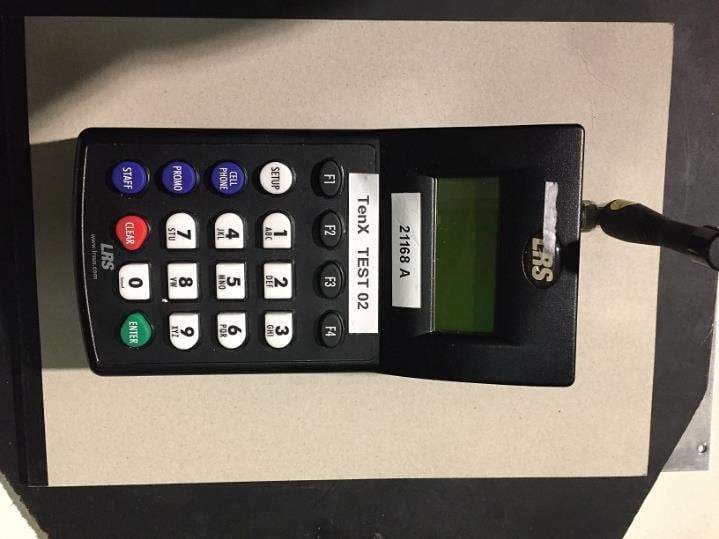
2AB6OTX7471
Mar 11, 2020Paging transmitter
Equipment Class
TNB - Licensed Non-Broadcast Station Transmitter
2AB6OTX7470
Apr 28, 2015Paging Transmitter for restaurant seating
Equipment Class
TNB - Licensed Non-Broadcast Station Transmitter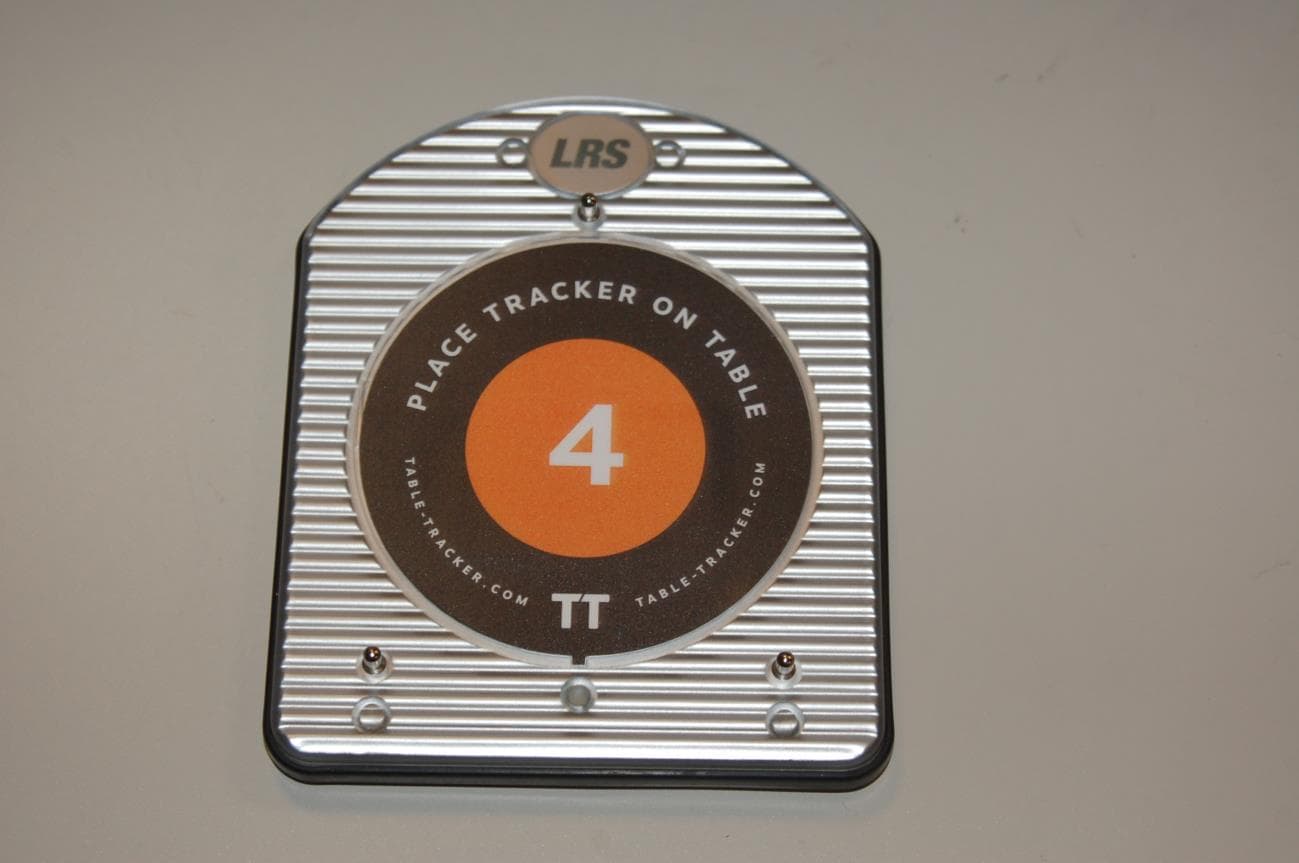
2AB6OTRACKER
Feb 23, 2015Table-Tracking Paging Receiver
Equipment Class
DXX - Part 15 Low Power Communication Device Transmitter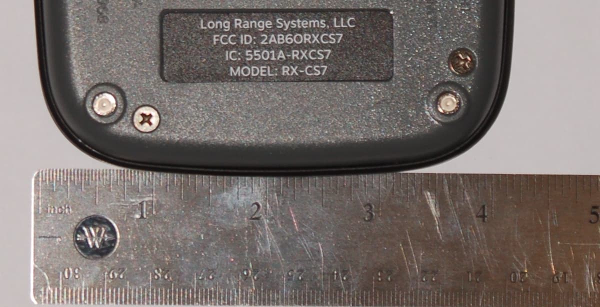
2AB6ORXCS7
Feb 12, 2015Paging Receiver
Equipment Class
DSC - Part 15 Security/Remote Control Transmitter
2AB6OTX3B25A
Sep 17, 2014Short range push for service transceiver
Equipment Class
DTS - Digital Transmission System