2ASIV-PGI302FCLOCKLY GUARD INGRESS
PIN GENIE, INC. DBA LOCKLY
Click to zoom
Application Details
- Equipment Class
- DXX - Part 15 Low Power Communication Device Transmitter
- Date of Grant
- Jan 10, 2023
- Application Purpose
- Original Equipment
- Date of Application
- Jan 10, 2023
- Equipment Note
- LOCKLY GUARD INGRESS
- Frequency Range
- 13.56000000 - 13.56000000
- Company
- PIN GENIE, INC. DBA LOCKLY
- Country
- United States
Documents & Files
Document Text
Text extracted from the exhibit documents filed with the FCC. Open a document above to read the original.
Users Manual
R PL3542Q/PGI302STM000,REV.BUMPGL302FC20220916110x170mm, 80G,,1632ROHS2.0,REACH,POPs,PAHS,PROP65, ERPPL3542Q-GL-SMT00030A-V2ERP P/N: REV0.1 K ËÍÛÎ ÓßÒËßÔ WWW.LOCKLYPRO.COM FOR COMMERCIAL USE & PROFESSIONAL INSTALLATION TIP ACTIVATION CODE CARD 2.1 Product Overview 2.2 Wiring Diagram 2.4 Rebooting Your Lock Section 1 - Product Highlights Section 2 - Product Overview Section 3 - Using Your Smart Lock 1.1 Product Features 4.3 Unlocking with RFID 4.4 Unlock with QR Code 2.3 Installation Diagram 3.1 Programming Mode 3.2 Configuring Access Codes 3.3 Understanding Your New Lock 3.5 Add Wireless Device through App 3.6 4.5 Safe Mode - Overview 4.6 Disabling Safe Mode 4.8 Tamper Switch 4.7 Welcome Mode Section 5- Video Doorbell 5.1 Video Doorbell 6.2 Multi Units and Tiered Verifications Section 7 - Important Notes Section 6 - Advanced Features 7.1 Important Notes Section 9 - Safety Precautions 9.1 Safety Precautions Section 8 - Cleaning 8.1 Cleaning TABLE OF CONTENTS Section 4 - Locking and Unlocking 4.1 Unlocking with Access Codes 4.2 Unlocking with Fingerprint 6.1 Offline Access Code TM (OAC) For additional support, visit Locklypro.com/support or email: [email protected] Pairing to a New Mobile Device 3.4 Pair Lock with the LocklyPro App 1.1 Product Features SECTION 1.11 Video Monitoring and Recording (PGI303) Full HD video camera streaming directly to your smartphone in real-time, gives a head to toe 130° view angle of who's at your front door. Video recordings are stored locally with no monthly fees. Patented Hack-Proof PIN Genie Keypad Digits are randomly displayed on the keypad ensuring access codes to be undetectable to intruders after repeated use. Numbers are randomly distributed across 4 buttons, with 3 numbers in each button. Users can press any button showing their number. Location of the numbers are always different everytime someone uses the keypad, making it hard for prying eyes to guess the correct code. Multiple Access Codes & Monitoring Store up to 999 Access Codes for family, friends and guests, as well as monitor entry and exit records. (Basic:15 Access Codes; Premium: 999 Access Codes) Live Monitoring Through your smartphone, monitor door access from anywhere in the world and securely control who comes and goes. Offline Access Code™ (OAC) The offline access code can allow owners to issue access codes, set the allowed access duration, without connecting the Lockly Guard to the internet in case of power outage, you can still remotely issue an Access Codes without any connection to the web. Auto-Lock Users no longer have to worry about forgetting to lock the door. With Auto Lock enabled, Lockly Guard will automatically auto-lock the door based on your customized timing set between 5-300 seconds. Multi-Tier Access Verification Improved security with a combination of fingerprint, password or RFID card access verification before unlocking. Upgradable Property Management Solution Programmed to manage a single household, office unit or upgrade to multiple unit management to grant sub-admin access and control to tenants or unit residents. It can also be used as employee access management system. 2.1 Product Overview - PGI302 SECTION 2.12 Anti-Theft Alarm Cable/Wire Outlet Speaker Port Program Button Reset Button Wiring 12345678 1 2 3 4 Lock Control Port Door Open Detection Port Door Exit Button Port + Door Exit Button Port - Doorbell Button Port 5 Doorbell Button Port + Wiegand 26 Data 0 Wiegand 26 GND 1 Wiegand 26 Data 1 6 Doorbell Signal Port 8 Access Control Power - 7 Access Control Power + Doorbell Power - Doorbell Power + PUSH LOCKLY NC BUTTON-SW GND1 BELL-SW BELL GND2 DC12V To ensure the device works properly, make sure the wires are connected according to this diagram. Touchscreen Keypad Doorbell Fingerprint LED Indicator Touchscreen Keypad 2.1 Product Overview - PGI303 Doorbell RFID Card Reader Fingerprint LED Indicator Anti-Theft Alarm Cable/Wire Outlet SECTION 2.13 Full HD video Camera Speaker Port Program Button Reset Button Wiring 12345678 1 2 3 4 Lock Control Port Door Open Detection Port Door Exit Button Port + Door Exit Button Port - Doorbell Button Port 5 Doorbell Button Port + Wiegand 26 Data 0 Wiegand 26 GND 1 Wiegand 26 Data 1 6 Doorbell Signal Port 8 Access Control Power - 7 Access Control Power + Doorbell Power - Doorbell Power + PUSH LOCKLY NC BUTTON-SW GND1 BELL-SW BELL GND2 DC12V To ensure the device works properly, make sure the wires are connected according to this diagram. Welcome /Safe Mode SECTION 2.24 2.2 Wiring Diagram Electromagnetic Lock A V+ V- NO COM NC Electromagnetic Lock B V+ V- NO COM NC Access Control Power Supply 1 NOORNC AC100-240 23 12345678 Access Control Wireless Transceiver +12V GND PUSH GND PUSH 12V LOCK NC Exit Button BUTTON-SW Data 0 Data 1 GND 1 GND1 Wiegand 26 Lockly Wireless Exit Button do not require cable connection. PUSH NC On Wireless Installation, PUSH and NC cables should connect to PUSH GND and LOCK NC on the wireless transceiver terminals. Note: The NC port is used to detect the opening and closing status of the door. Only the Lockly Guard Electro- magnetic Lock supports this function. If you use a third-party Electroma- gnetic Lock other than the Lockly Guard Electromagnetic Lock, you do not need to connect this NC cable. 2.3 Installation Diagram 2.3.1 Wired Installation 2.3.2 Wireless Installation SECTION 2.35 Access Control DC 12V GND Power Supply V+ V- Power Supply Wireless Exit Button Electromagnetic Lock Electromagnetic Lock V+ NO OR NC COM V- NC LOCK NC Power Supply Wireless Transceiver Wireless Transceiver +12V GND PUSH GND Power Supply V+ V- PUSH Exit Button BUTTON-SW GND1 Access Control DC 12V GND PUSH- Power Supply V+ V- PUSH Power Supply Electromagnetic Lock Electromagnetic Lock V+ NO OR NC COMV- NC LOCK NC Power Supply Access Control 2.4 Rebooting Your Lock Press and release the reboot button when you want to reset the lock. Your Lockly Guard will beep once after reboot. Only reboot when necessary. Reboot button…
Text truncated - open the document above for the full version.
External Photos
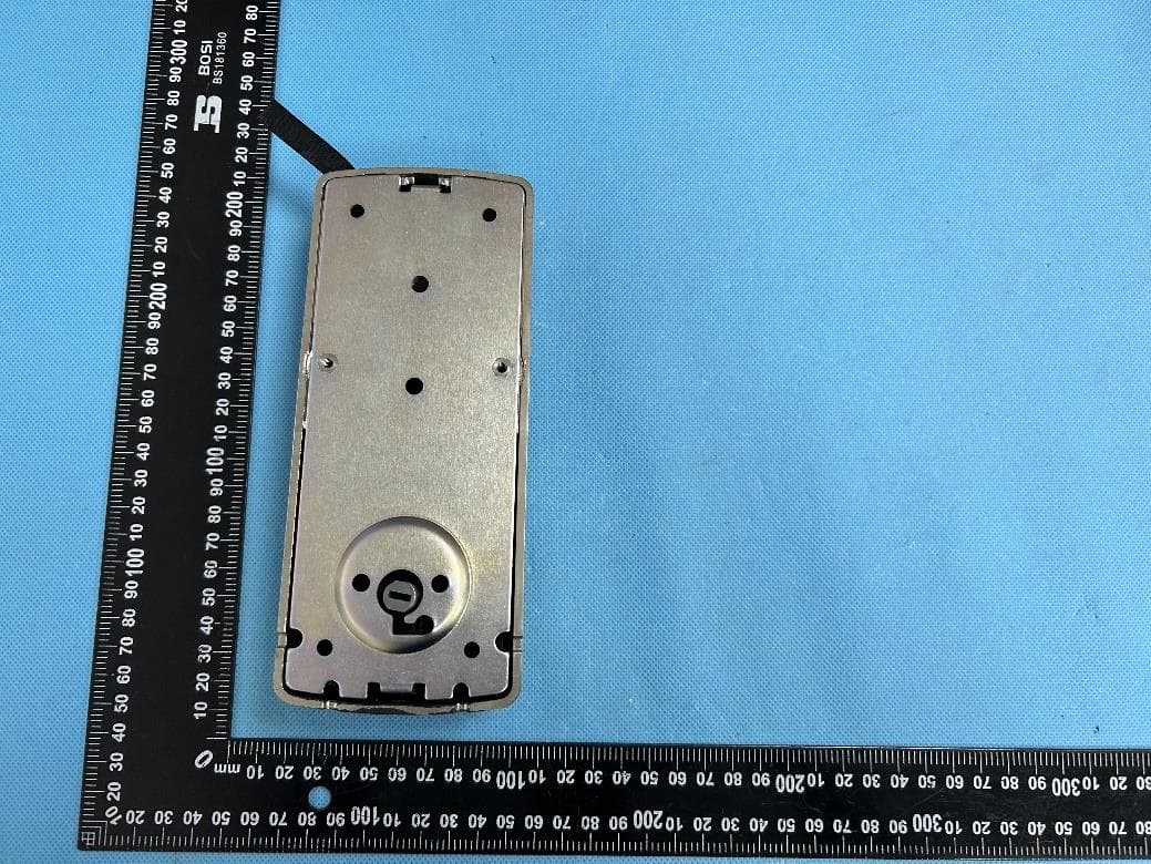
Reference No.: WTX22X09197704W001/002/003 Page 2 of 12 Waltek Testing Group (Shenzhen) Co., Ltd. Http://www.waltek.com.cn EXHIBIT 2 - EUT EXTERNAL PHOTOGRAPHS EUT View 1 EUT View 2 Reference No.: WTX22X09197704W001/002/003 Page 3 of 12 Waltek Testing Group (Shenzhen) Co., Ltd. Http://www.waltek.com.cn EUT View 3 EUT View 4 Reference No.: WTX22X09197704W001/002/003 Page 4 of 12 Waltek Testing Group (Shenzhen) Co., Ltd. Http://www.waltek.com.cn EUT View 5 EUT View 6
ID Label/Location Info
Reference No.: WTX22X09197704W001/002/003 Page 1 of 12 Waltek Testing Group (Shenzhen) Co., Ltd. Http://www.waltek.com.cn ANNEX EXHIBIT 1 - PRODUCT LABELING Proposed FCC ID Label Format Specifications: The label shall be securely affixed to a permanently attached part of the device, in a location where it is visible or easily accessible to the user, and shall not be readily detachable. The label shall be sufficiently durable to remain fully legible and intact on the device in all normal conditions of use throughout the device’s expected lifetime. Proposed Label Location on EUT FCC ID Label Location
Internal Photos
Reference No.: WTX22X09197704W001/002/003 Page 5 of 12 Waltek Testing Group (Shenzhen) Co., Ltd. Http://www.waltek.com.cn EXHIBIT 3 - EUT INTERNAL PHOTOGRAPHS EUT Housing and Board View 1 Solder Board-Component View 1 Reference No.: WTX22X09197704W001/002/003 Page 6 of 12 Waltek Testing Group (Shenzhen) Co., Ltd. Http://www.waltek.com.cn Solder Board-Component View 2 Solder Board-Component View 3 Reference No.: WTX22X09197704W001/002/003 Page 7 of 12 Waltek Testing Group (Shenzhen) Co., Ltd. Http://www.waltek.com.cn Solder Board-Component View 4 Solder Board-Component View 5 Reference No.: WTX22X09197704W001/002/003 Page 8 of 12 Waltek Testing Group (Shenzhen) Co., Ltd. Http://www.waltek.com.cn Solder Board-Component View 6 Antenna View 1 Reference No.: WTX22X09197704W001/002/003 Page 9 of 12 Waltek Testing Group (Shenzhen) Co., Ltd. Http://www.waltek.com.cn Antenna View 2
Test Report
Waltek Testing Group (Shenzhen) Co., Ltd. Http://www.waltek.com.cn Page 1 of 27 TEST REPORT Reference No. .................... : WTX22X09197704W002 FCC ID ................................ : 2ASIV-PGI302FC Applicant ........................... : PIN GENIE, INC. DBA LOCKLY Address.............................. : 676 Transfer Rd., St. Paul, MN 55114 Manufacturer ..................... : Smart Electronic Industrial (Dong Guan) Co., Ltd. Address.............................. : Qing Long Road, Long Jian Tian Village, Huang Jiang Town, Dong Guan, Guang Dong, China Product Name ................... : LOCKLY GUARD INGRESS Model No... ......................... : PGI302FC Standards .......................... : FCC Part 15.225 Date of Receipt sample .... : 2022-09-30 Date of Test........................ : 2022-09-30 to 2022-11-09 Date of Issue ..................... : 2022-11-09 Test Report Form No. ....... : WTX_Part 15_225W Test Result ......................... : Pass Remarks: The results shown in this test report refer only to the sample(s) tested, this test report cannot be reproduced, except in full, without prior written permission of the company. The report would be invalid without specific stamp of test institute and the signatures of approver. Prepared By: Waltek Testing Group (Shenzhen) Co., Ltd. Address: 1/F., Room 101, Building 1, Hongwei Industrial Park, Liuxian 2nd Road, Block 70 Bao'an District, Shenzhen, Guangdong, China Tel.: +86-755-33663308 Fax.: +86-755-33663309 Email: [email protected] Tested by: Approved by: Jack Huang Silin Chen Reference No.: WTX22X09197704W002 Waltek Testing Group (Shenzhen) Co., Ltd. Http://www.waltek.com.cn Page 2 of 27 TABLE OF CONTENTS 1. GENERAL INFORMATION ....................................................................................................................................4 1.1 PRODUCT DESCRIPTION FOR EQUIPMENT UNDER TEST (EUT) .........................................................................4 1.2 TEST STANDARDS .................................................................................................................................................5 1.3 TEST METHODOLOGY ...........................................................................................................................................5 1.4 TEST FACILITY ......................................................................................................................................................5 1.5 EUT SETUP AND TEST MODE ..............................................................................................................................6 1.6 MEASUREMENT UNCERTAINTY .............................................................................................................................7 1.7 TEST EQUIPMENT LIST AND DETAILS ...................................................................................................................8 2. SUMMARY OF TEST RESULTS ......................................................................................................................... 11 3. ANTENNA REQUIREMENT ................................................................................................................................. 12 3.1 STANDARD APPLICABLE ..................................................................................................................................... 12 3.2 TEST RESULT ...................................................................................................................................................... 12 4. RADIATED EMISSIONS ....................................................................................................................................... 13 4.1 STANDARD APPLICABLE ..................................................................................................................................... 13 4.2 TEST PROCEDURE .............................................................................................................................................. 13 4.3 CORRECTED AMPLITUDE & MARGIN CALCULATION ........................................................................................... 15 4.4 SUMMARY OF TEST RESULTS/PLOTS ................................................................................................................. 16 5. OUT OF BAND EMISSIONS ................................................................................................................................ 19 5.1 STANDARD APPLICABLE ..................................................................................................................................... 19 5.2 TEST PROCEDURE .............................................................................................................................................. 19 5.3 SUMMARY OF TEST RESULTS/PLOTS ................................................................................................................. 19 6. FREQUENCY STABILITY .................................................................................................................................... 21 6.1 STANDARD APPLICABLE ..................................................................................................................................... 21 6.2 TEST PROCEDURE .............................................................................................................................................. 21 6.3 SUMMARY OF TEST RESULTS/PLOTS ................................................................................................................. 21 7. EMISSION BANDWIDTH ...................................................................................................................................... 22 7.1 APPLICABLE STANDARD ..................................................................................................................................... 22 7.2 TEST PROCEDURE .............................…
Text truncated - open the document above for the full version.
Test Setup Photos
Reference No.: WTX22X09197704W001/002/003 Page 10 of 12 Waltek Testing Group (Shenzhen) Co., Ltd. Http://www.waltek.com.cn EXHIBIT 4 - TEST SETUP PHOTOGRAPHS Conducted Emission Test Setup Radiation Emission Test Setup (Below 30MHz) Reference No.: WTX22X09197704W001/002/003 Page 11 of 12 Waltek Testing Group (Shenzhen) Co., Ltd. Http://www.waltek.com.cn Radiation Emission Test Setup (30MHz to 1GHz) Radiation Emission Test Setup (1GHz to 18GHz) Reference No.: WTX22X09197704W001/002/003 Page 12 of 12 Waltek Testing Group (Shenzhen) Co., Ltd. Http://www.waltek.com.cn Radiation Emission Test Setup (Above 18GHz) ***** END OF REPORT *****
Contact Information
Applicant
Cindy zhou(COO)
Test Firm
Waltek Testing Group (Shenzhen) Co., Ltd.Jandy So
Technical Specifications
| # | Rule Parts | Frequency Range | Power Output |
|---|---|---|---|
| 1 | 15C | 13.56 MHz - 13.56 MHz | - |
Other Applications from PIN GENIE, INC. DBA LOCKLY
2ASIVPGD768FNU
Jun 22, 2024Lockly Guard Fingerprint Deadbolt 728FZ Z-Wave Smart Lock, Lockly Guard Deadbolt 728Z Z-Wave Smart Lock
Equipment Class
DTS - Digital Transmission System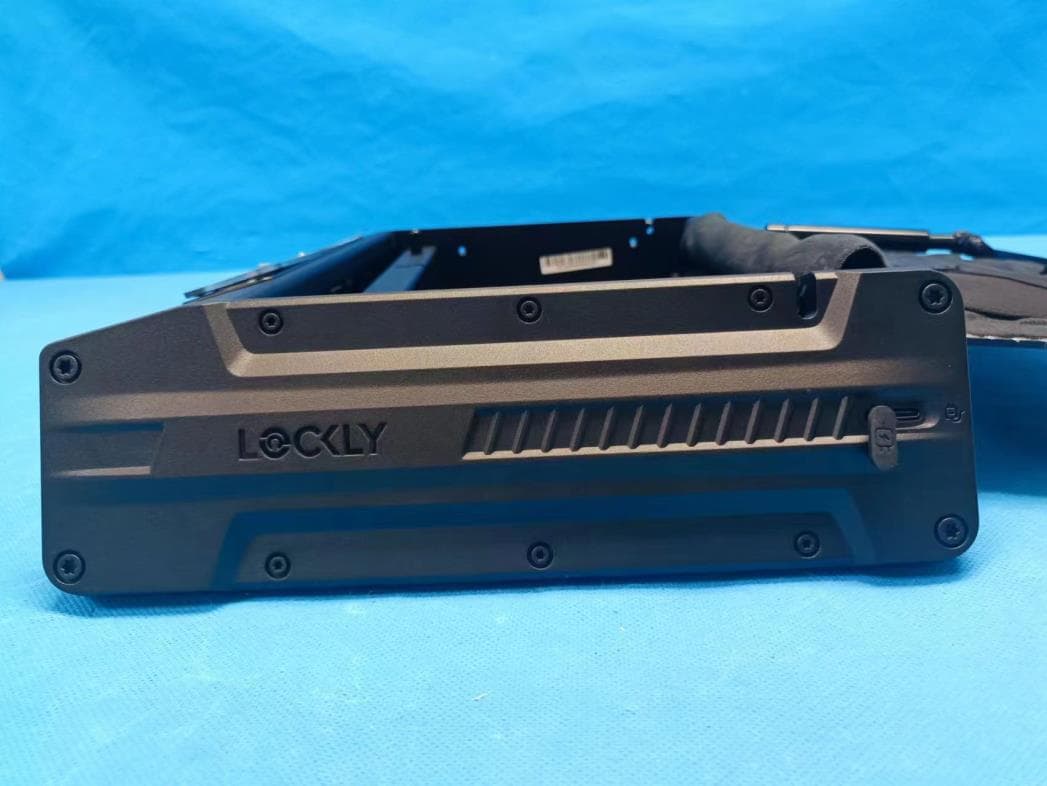
2ASIVPGV528WG30
Apr 21, 2023Lockly Smart Safe
Equipment Class
DTS - Digital Transmission System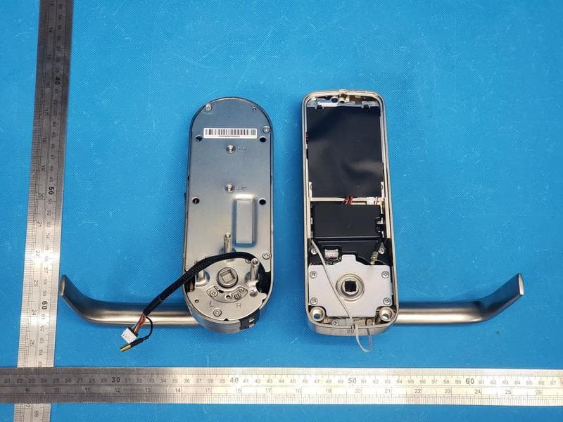
2ASIVPGD698
Apr 02, 2023Lockly Guard Vision
Equipment Class
DTS - Digital Transmission System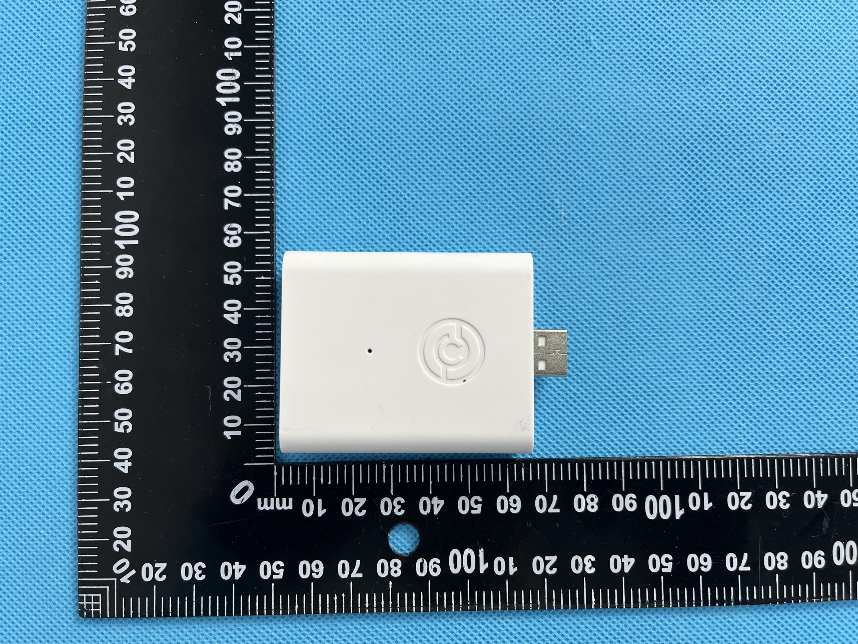
2ASIVPGH200UM
Feb 27, 2023ENABLES WI-FI, RF &BLE CONNECTIVITY FOR LOCKLY SMART LOCKS
Equipment Class
DTS - Digital Transmission System
2ASIVPGD238LFC
Nov 21, 2022Electronic Mortise lock
Equipment Class
DTS - Digital Transmission System