2ASIVPGD238LFCElectronic Mortise lock
PIN GENIE, INC. DBA LOCKLY
Click to zoom
Application Details
- Equipment Class
- DTS - Digital Transmission System
- Date of Grant
- Nov 21, 2022
- Application Purpose
- Original Equipment
- Date of Application
- Nov 21, 2022
- Equipment Note
- Electronic Mortise lock
- Frequency Range
- 2402.00000000 - 2480.00000000
- Company
- PIN GENIE, INC. DBA LOCKLY
- Country
- United States
Documents & Files
Document Text
Text extracted from the exhibit documents filed with the FCC. Open a document above to read the original.
Users Manual
WWW.LOCKLYPRO.COM FOR COMMERCIAL USE & PROFESSIONAL INSTALLATION USER MANUAL Electronic Mortise lock PGD238FC REV:1.0 Date:2022-09-07 ERP机型:PL45H1UQ-US-SMT00030A-V1 DesignerSabrina K 描述:PL45H1UQ/PGD238SMT000,REV.A(UMPGD23820220907) 140x190mm80g1632RoHS2.0REACH Prop65POPsPAHs ERP P/N: R TABLE OF CONTENTS Table of Contents 25 26 27 27 Section 5 - Advanced Features Section 6 - Important Notes Section 7 - Cleaning Section 8 - Safety Precautions 5.1 Offline Access Code TM (OAC) Section 1 - Product Highlights Section 2 - Product Overview 2.1 Product Overview- Exterior 2.2 Understanding Your New Lock 2.3 Locking/Unlocking with App 2.4 Rebooting Lockly Guard 2.5 Low Battery 2.6 Changing the Battery 1.1 Product Features Section 3 - Using Your Smart Lock 3.1 Configuring Access 3.2 Entering Programming Mode 3.3 Pairing to a New Mobile Device 3.4 Adding an Access Code 3.5 Delete/Query an Access Code 3.6 Adding a Fingerprint 3.7 Add/Remove Fingerprints 3.8 Fingerprint Scanning Directions 3.9 Fingerprint Scanning Tips & Troubleshoot 3.10 Adding an RFID card 3.11 Delete/Query RFID Card Section 4 - Locking and Unlocking 2 3 3 4 5 6 1 7 8 8 10 10 11 12 13 14 14 15 16 17 18 19 20 22 23 24 24 4.1 Unlocking with Access Codes 4.2 Unlocking/Locking with Fingerprints 4.3 Unlocking using RFID 4.4 Locking/Unlocking with Physical Key 4.5 Safe Mode 4.6 Locking from the Outdoor 4.7 Rain Mode 4.8 Shine Mode 4.9 Welcome Mode For additional support, visit http:// LocklyPro.com/support or email [email protected] SECTION 1.11 Patented Hack-proof PIN Genie Keypad Digits are randomly displayed on the keypad ensuring access codes to be undetectable to intruders after repeated use. Numbers are randomly distributed across 4 buttons, with 3 numbers in each button. Users can press any button showing their number. Location of the numbers are always different everytime someone uses the keypad, making it hard for prying eyes to guess the correct code. Multiple Access Codes & Monitoring Store up to 1033 Access Codes and monitor each entry and exit records. Advanced 3D Fingerprint Recognition Biometric Fingerprint Recognition protocol allows up to 99 registered fingerprints to be used and accepts only actual fingerprints - preventing lifted prints from being used. RFID Card Access Store up to 999 MIFARE RFID card Live Monitoring Through your smartphone, monitor door access from anywhere in the world and securely control who comes and goes. Offline Access Code TM (OAC) The offline access code TM can allow owners to issue access codes, set the allowed access duration, all without Lockly Guard ever connecting to the internet, so in case of power outage, you can still magically and remotely issue Access Codes without any connection to the web. Automatic Lock Owners no longer have to worry about forgetting to lock the door. With Auto Lock enabled, Lockly Guard will automatically re-lock the door based on your customized timing set between 5-300 seconds. (Note: Auto locking only supports latches) Backup Keys and 9V Battery Socket The door can be opened with physical backup keys. There is also a 9V battery connection socket for emergency power backup to access the keypad in case your smart lock runs out of battery. 1.1 Product Features 2SECTION 2.1 2.1 Product Overview- Exterior Program Button Reboot Button 9V alkaline battery Battery Compartment *Operated by 4 X AA size alkaline batteries ( not included ) Welcome/ Safe Mode Battery Indicator OK Button Exterior Handle Battery Cover Touchscreen Keypad RFID Card Reader Key Hole Fingerprint Reader SECTION 2.2 ~ 2.33 After the installation of your new Lockly Guard, understanding some key functions of operating your smart lock is important. The following guides will walk you through resetting a lock, adding and deleting Access Codes, adding and deleting fingerprints, adding and deleting RFID cards and also how to configure your OAC (Offline Access Code™) For any questions you can always visit http://LocklyPro.com/support for assistance. . 2.2 Understanding Your New Lock The Default Access Code is 1 2 3 4 5 6 NOTICE 2.3 Locking/Unlocking with App Lockly Guard works best with our iOS and Android app. You must have the LocklyPro iOS or Android app installed in order to lock and unlock with smartphone. Download the app by visiting the link below or search "LocklyPro" from the correct app store. Scan or visit LocklyPro.com/app PR O 4SECTION 2.4 2.4 Rebooting Lockly Guard Press and release the reboot button when you want to reboot the lock. Your Lockly Guard will beep once after reboot. Only reboot when necessary. To reboot, find the restart button from the bottom of Lockly Guard. You will need something small such as a paperclip, to press the reboot button. Insert the paper clip and press down firmly. NOTICE Reboot Lockly Guard in case of dead battery or malfunction. No settings will be changed and all Access Codes will still be stored within Lockly Guard. Reboot Button SECTION 2.55 When the battery is in seriously low condition, Lockly Guard will make continuous beep- ing sounds in addition to the flashing low battery icon on the touch screen. You should replace batteries immediately to avoid your smart lock from shutting down. When your smart lock low-battery warning alert finally dies, you will have 3 chances to unlock your smart lock either by a password, APP or fingerprint. If the unlock was successful, the low-battery warning alert will be on for 1 minute. After which, the smart lock will go to dead-battery mode and will lock auto lock in 5 seconds and the screen will display a low-battery icon. Your Lockly will automatically detect battery polarity. So hold your 9V battery lead in place against bottom of the Lockly to temporarily activate the screen to enter your Access Code. Be sure to hold the 9V battery against the contact points located at the bottom of the lock until you have successfully unlocked your door with your Access Code. Once unlocked, batteries should be replaced immediately…
Text truncated - open the document above for the full version.
Cover Letter(s)
PINGENIE,INC.DBALOCKLY 676TransferRd.,St.Paul,Minnesota55114,UnitedStates Date:2022-11-04 FederalCommunicationsCommission AuthorizationandEvaluationDivision 7435OaklandMillsRoad Columbia,MD21046 FCCID:2ASIVPGD238LFC ConfidentialityRequest Towhomitmayconcern, PursuanttotheprovisionsoftheCommission’srulesTitle47Sections§0.457and§0.459,weare requestingtheCommissiontowithholdthefollowingattachment(s)asconfidentialdocumentsfrompublic disclosureindefinitely. ☒ BlockDiagram ☐ Tune-UpInformation ☒ OperationalDescription ☐ SecurityInformation ☒ Schematics ☐ SoftwareDefinedRadio(SDR)Information ☐ PartsList Theabovematerialscontaintradesecretsandproprietaryinformationnotcustomarilyreleasedtothe public.Thepublicdisclosureofthesematerialsmaybeharmfultotheapplicantandprovideunjustified benefitstoitscompetitors. Inadditionaltoabovementioneddocuments,inordertocomplywiththemarketingregulationsinTitle47 CFR§2.803andtheimportationrulesinTitle47CFR§2.1204,whileensuringthatbusinesssensitive informationremainsconfidentialuntiltheactualmarketingofnewlyauthorizeddevices,werequestShort TermConfidentialityofthefollowingattachment(s); ☐ ExternalPhotos ☐ TestSetupPhotos ☐ InternalPhotos ☐ UserManual ☐For45days,pursuanttoPublicNoticeDA04-1705. or ☐ For180dayspursuanttoKDB726920D01. TheapplicantunderstandsthatpursuanttoSection0.457oftheRules,disclosureofthisapplicationand allaccompanyingdocumentationwillnotbemadebeforethedateoftheGrantforthisapplication. Sincerely, PINGENIE,INC.DBALOCKLY ------------------------------- Cindyzhou/COO
Cover Letter(s)
PINGENIE,INC.DBALOCKLY 676TransferRd.,St.Paul,Minnesota55114,UnitedStates -------------------------------------------------------------------------------- (FCCID : 2ASIVPGD238LFC) POWEROFATTORNEY DATE:2022-11-04 FederalCommunicationsCommission AuthorizationandEvaluationDivision 7435OaklandMillsRoad Columbia,MD21046 ToWhomItMayConcern: We,theundersigned,herebyauthorizeWaltekTestingGroup(Shenzhen)Co.,Ltd. JandySoonourbehalf,toapplytotheFederalCommunicationsCommissiononour equipment.AnyandallactscarriedoutbyWaltekTestingGroup(Shenzhen)Co., Ltd.JandySoonourbehalfshallhavethesameeffectasactsofourown. ThisistoadvisethatweareinfullcompliancewiththeAnti-DrugAbuseAct. We,PINGENIE,INC.DBALOCKLYarenotsubjecttoadenialoffederalbenefits pursuanttoSection5301oftheAnti-DrugActof1988,21USC853a,andnoparty totheapplicationissubjecttoadenialoffederalbenefitspursuanttothat section. Sincerely, PINGENIE,INC.DBALOCKLY ------------------------------- (Cindyzhou) (COO)
External Photos
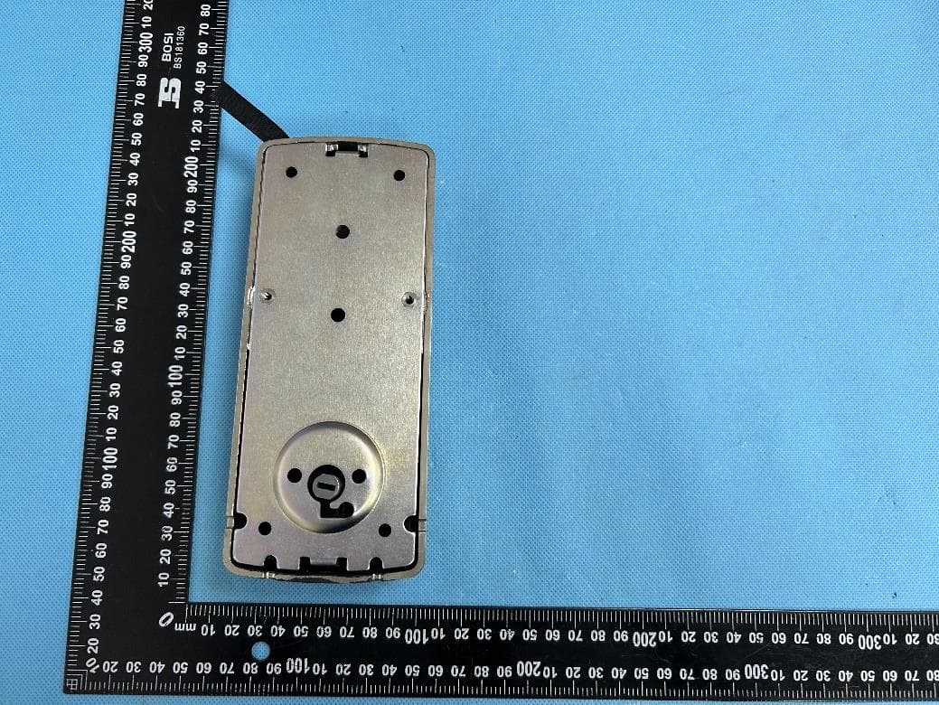
Reference No.: WTX22X09196553W001/002 Page 2 of 12 Waltek Testing Group (Shenzhen) Co., Ltd. Http://www.waltek.com.cn EXHIBIT 2 - EUT EXTERNAL PHOTOGRAPHS EUT View 1 EUT View 2 Reference No.: WTX22X09196553W001/002 Page 3 of 12 Waltek Testing Group (Shenzhen) Co., Ltd. Http://www.waltek.com.cn EUT View 3 EUT View 4 Reference No.: WTX22X09196553W001/002 Page 4 of 12 Waltek Testing Group (Shenzhen) Co., Ltd. Http://www.waltek.com.cn EUT View 5 EUT View 6 Reference No.: WTX22X09196553W001/002 Page 5 of 12 Waltek Testing Group (Shenzhen) Co., Ltd. Http://www.waltek.com.cn EUT View 7 EUT View 8
ID Label/Location Info
Reference No.: WTX22X09196553W001/002 Page 1 of 12 Waltek Testing Group (Shenzhen) Co., Ltd. Http://www.waltek.com.cn ANNEX EXHIBIT 1 - PRODUCT LABELING Proposed FCC ID Label Format Specifications: The label shall be securely affixed to a permanently attached part of the device, in a location where it is visible or easily accessible to the user, and shall not be readily detachable. The label shall be sufficiently durable to remain fully legible and intact on the device in all normal conditions of use throughout the device’s expected lifetime. Proposed Label Location on EUT FCC ID Label Location
Internal Photos
Reference No.: WTX22X09196553W001/002 Page 10 of 12 Waltek Testing Group (Shenzhen) Co., Ltd. Http://www.waltek.com.cn Antenna View
Internal Photos
Reference No.: WTX22X09196553W001/002 Page 6 of 12 Waltek Testing Group (Shenzhen) Co., Ltd. Http://www.waltek.com.cn EXHIBIT 3 - EUT INTERNAL PHOTOGRAPHS EUT Housing and Board View 1 Solder Board-Component View 1 Reference No.: WTX22X09196553W001/002 Page 7 of 12 Waltek Testing Group (Shenzhen) Co., Ltd. Http://www.waltek.com.cn Solder Board-Component View 2 Solder Board-Component View 3 Reference No.: WTX22X09196553W001/002 Page 8 of 12 Waltek Testing Group (Shenzhen) Co., Ltd. Http://www.waltek.com.cn Solder Board-Component View 4 Solder Board-Component View 5 Reference No.: WTX22X09196553W001/002 Page 9 of 12 Waltek Testing Group (Shenzhen) Co., Ltd. Http://www.waltek.com.cn Solder Board-Component View 6 Solder Board-Component View 7
RF Exposure Info
1. RF Exposure Requirements 1.1 General Information Client Information Applicant: PIN GENIE, INC. DBA LOCKLY Address of applicant: 676 Transfer Rd., St. Paul, MN 55114 Manufacturer: Smart Electronic Industrial (Dong Guan) Co., Ltd. Address of manufacturer: Qing Long Road, Long Jian Tian Village, Huang Jiang Town, Dong Guan, Guang Dong, China General Description of EUT: Product Name: Electronic Mortise lock Trade Name LOCKLY Model No.: PGD238FC Adding Model(s): / Rated Voltage: DC 6V Battery Capacity: / FCC ID: 2ASIVPGD238LFC Equipment Type: Mobile device Technical Characteristics of EUT: Bluetooth Bluetooth Version: V5.0 (BLE mode) Frequency Range: 2402-2480MHz RF Output Power: -10.66dBm (Conducted) Data Rate: 1Mbps Modulation: GFSK Quantity of Channels: 40 Channel Separation: 2MHz Type of Antenna: FPC Antenna Antenna Gain: 1.3dBi NFC Support Standards: NFC Frequency Range: 13.56MHz Max. Field Strength: 47.83dBuV/m (at 3m) Antenna Type: Integral Antenna Antenna Gain 0dBi 1.2 RF Exposure Exemption According to §1.1307(b)(3) and 447498 D04 Interim General RF Exposure Guidance v01, system operating under the provisions of this section shall be operating in a manner that the public is not exposed to radio frequency energy level in excess limit for maximum permissible exposure. Option A: FCC Rule Part 1.1307 (b)(3)(i)(A):The available maximum time-averaged power is no more than 1mW, regardless of separation distance. Option B: FCC Rule Part 1.1307 (b)(3)(i)(B): The available maximum time-averaged power or effective radiated power (ERP), whichever is greater, is less than or equal to the threshold P th (mW) described in the following formula. P th is given by: Option C: FCC Rule Part 1.1307 (b)(3)(i)(C): The minimum separation distance (R in meters) from the body of a nearby person for the frequency (f in MHz) at which the source operates, the ERP (watts) is no more than the calculated value prescribed for that frequency. R must be at least λ/2π, where λ is the free-space operating wavelength in meters. Single RF Sources Subject to Routine Environmental Evaluation RF Source frequency (MHz) Threshold ERP (watts) 0.3-1.34 1,920 R 2 1.34-30 3,450 R 2 /f 2 30-300 3.83 R 2 300-1,500 0.0128 R 2 f 1,500-100,000 19.2R 2 For Multiple RF sources: FCC Rule Part 1.1307(b)(3)(ii): (A) The available maximum time-averaged power of each source is no more than 1 mW and there is a separation distance of two centimeters between any portion of a radiating structure operating and the nearest portion of any other radiating structure in the same device, except if the sum of multiple sources is less than 1 mW during the time-averaging period, in which case they may be treated as a single source (separation is not required). (B) In the case of fixed RF sources operating in the same time-averaging period, or of multiple mobile or portable RF sources within a device operating in the same time averaging period, if the sum of the fractional contributions to the applicable thresholds is less than or equal to 1 as indicated in the following equation. 1.3 Calculated Result Radio Access Technology Min. Frequency Max. Output Power Max. Tune-Up Output Power Antenna Gain Duty Cycle Tune-Up EIRP (MHz) (dBm) (dBm) (dBi) (%) (dBm) Bluetooth 2402 -10.66 -10.00 1.3 100 -8.7 Frequency Option Min. Distance Tune-Up ERP Exposure Limit Ratio Result (MHz) (cm) (dBm) (mW) (mW) Pass/Fail 2402 C 20.00 -10.85 0.08 768.00 0.01 Pass Note: 1. ERP=EIRP-2.15dB; EIRP= Output Power + Antenna gain 2. Option A, B and C refers as clause 1.2. 3. For option B, Pth(mW) convert to Exposure Limit(mW); For option C, ERP(W) convert to Exposure Limit(mW). 4. Ratio= Tune-Up ERP(mW)/ Exposure Limit (mW) Mode for Simultaneous Multi-band Transmission: Radio Access Technology Ratio 1 Ratio 2 Simultaneous Ratio Limit Result Pass/Fail -- -- -- -- -- -- Result: Pass
Test Report
ShenzhenGolden-Resource Electronic Co.,Ltd. SPECIFICATION FOR APPROVAL Date 2022/11/18 File No 22111801 Revision 1.0 CUSTOMER: SMART ELECTRONIC INDUSTRIAL CO.,LTD. CUSTOMER NO: ETGGD23800010-JLY BTAntenna PART NAME: BT Antenna SUPPLIER NO: YJW01.029.103.301A Date: Q"TY: PCS CUSTOMER APPROVED BY APPROVALCHIEFSUPERVISOR SUPPLIER SIGNATURE APPROVALCHECKDESIGN add: 17A-03A, Block B, Nanxian Commercial Plaza, Meilong Road, Longhua New District, Shenzhen APPROVALCHECKDESIGN ChenGuoqiangXieLiChenXingcheng YJ-RD-F04-A Spec ltem NO . Contents Number of Page Page Code 1 Spec Cover11 2 Spec Item 12 3Drawing133Drawing13 4 Antenna Specification14 5 S Parameter 15 6 Passive Test26 ~ 7 7 Radiation Pattern 28 ~ 9 8 Antenna Profile210 ~ 11 9 10-- 11N/AN/AN/A add: 17A-03A, Block B, Nanxian Commercial Plaza, Meilong Road, Longhua New District, Shenzhen 12--- 13--- - - - - - Antenna Specification Electrical Properties Frequency 2.4-2.5GHz qy Impedance50 Ohm Nominal V.S.W.R2.0 Max Gain 14dBi Gain 1.4 dBi RadiationOmni-directional PolarizationLinear Physical Properties ConnectorMCX plug Cable TypeO.D.1.37mm Cable Length76mm Cable ColorBlack add: 17A-03A, Block B, Nanxian Commercial Plaza, Meilong Road, Longhua New District, Shenzhen Operating Temp.-40 ~ +85 ̊C Storage Temp / Humidity 25±5 ̊C / <70% AntennaPerformance Test Agilent Antenna Performance Te s t Agilent E5071B SS Parameter Test // BT Antenna add: 17A-03A, Block B, Nanxian Commercial Plaza, Meilong Road, Longhua New District, Shenzhen Antenna Passive TestAntenna Passive Te s t Z Y XX X Z Y X add: 17A-03A, Block B, Nanxian Commercial Plaza, Meilong Road, Longhua New District, Shenzhen Passive Test For BT Antenna FreqEffiEffiGain (MHz)(%)(dB)(dBi) 2400 76.2-1.21.4 2410 76.9-1.11.2 2420 75.3-1.21.0 2430 75.2-1.21.1 2440 74.8-1.31.1 2450 76.0-1.21.2 2460 72.6-1.41.1 2470 74.1-1.31.3 2480 71.6-1.51.2 add: 17A-03A, Block B, Nanxian Commercial Plaza, Meilong Road, Longhua New District, Shenzhen 2490 70.5-1.51.0 2500 64.1-1.90.7 Radiation Pattern For BT Antenna(2450MHz) add: 17A-03A, Block B, Nanxian Commercial Plaza, Meilong Road, Longhua New District, Shenzhen BT Antenna add: 17A-03A, Block B, Nanxian Commercial Plaza, Meilong Road, Longhua New District, Shenzhen add: 17A-03A, Block B, Nanxian Commercial Plaza, Meilong Road, Longhua New District, Shenzhen
Test Report
Waltek Testing Group (Shenzhen) Co., Ltd. Http://www.waltek.com.cn Page 1 of 36 TEST REPORT Reference No. .................... : WTX22X09196553W001 FCC ID ................................ : 2ASIVPGD238LFC Applicant ........................... : PIN GENIE, INC. DBA LOCKLY Address.............................. : 676 Transfer Rd., St. Paul, MN 55114 Manufacturer ..................... : Smart Electronic Industrial (Dong Guan) Co., Ltd. Address.............................. : Qing Long Road, Long Jian Tian Village, Huang Jiang Town, Dong Guan, Guang Dong, China Product Name ................... : Electronic Mortise lock Model No.. .......................... : PGD238FC Standards .......................... : FCC Part 15.247 Date of Receipt sample .... : 2022-09-28 Date of Test........................ : 2022-09-28 to 2022-10-26 Date of Issue ..................... : 2022-10-26 Test Report Form No. ....... : WTX_Part 15_247W Test Result ......................... : Pass Remarks: The results shown in this test report refer only to the sample(s) tested, this test report cannot be reproduced, except in full, without prior written permission of the company. The report would be invalid without specific stamp of test institute and the signatures of approver. Prepared By: Waltek Testing Group (Shenzhen) Co., Ltd. Address: 1/F., Room 101, Building 1, Hongwei Industrial Park, Liuxian 2nd Road, Block 70 Bao'an District, Shenzhen, Guangdong, China Tel.: +86-755-33663308 Fax.: +86-755-33663309 Email: [email protected] Tested by: Approved by: Jack Huang Silin Chen Reference No.: WTX22X09196553W001 Waltek Testing Group (Shenzhen) Co., Ltd. Http://www.waltek.com.cn Page 2 of 36 TABLE OF CONTENTS 1. GENERAL INFORMATION ...................................................................................................................................4 1.1 PRODUCT DESCRIPTION FOR EQUIPMENT UNDER TEST (EUT) .........................................................................4 1.2 TEST STANDARDS .................................................................................................................................................5 1.3 TEST METHODOLOGY ...........................................................................................................................................5 1.4 TEST FACILITY ......................................................................................................................................................5 1.5 EUT SETUP AND TEST MODE ..............................................................................................................................6 1.6 MEASUREMENT UNCERTAINTY .............................................................................................................................7 1.7 TEST EQUIPMENT LIST AND DETAILS ...................................................................................................................8 2. SUMMARY OF TEST RESULTS ......................................................................................................................... 11 3. ANTENNA REQUIREMENT ................................................................................................................................ 12 3.1 STANDARD APPLICABLE ..................................................................................................................................... 12 3.2 EVALUATION INFORMATION ................................................................................................................................ 12 4. POWER SPECTRAL DENSITY ........................................................................................................................... 13 4.1 STANDARD APPLICABLE ..................................................................................................................................... 13 4.2 TEST SETUP BLOCK DIAGRAM ........................................................................................................................... 13 4.3 TEST PROCEDURE .............................................................................................................................................. 13 4.4 SUMMARY OF TEST RESULTS/PLOTS ................................................................................................................. 13 5. DTS BANDWIDTH ................................................................................................................................................. 14 5.1 STANDARD APPLICABLE ..................................................................................................................................... 14 5.2 TEST SETUP BLOCK DIAGRAM ........................................................................................................................... 14 5.3 TEST PROCEDURE .............................................................................................................................................. 14 5.4 SUMMARY OF TEST RESULTS/PLOTS ................................................................................................................. 14 6. RF OUTPUT POWER ............................................................................................................................................ 15 6.1 STANDARD APPLICABLE ..................................................................................................................................... 15 6.2 TEST SETUP BLOCK DIAGRAM ........................................................................................................................... 15 6.3 TEST PROCEDURE .............................................................................................................................................. 15 6.4 SUMMARY OF TEST RESULTS/PLOTS ................................................................................................................. 15 7. FIELD STRENGTH OF SPURIOUS EMISSIONS ......…
Text truncated - open the document above for the full version.
Test Setup Photos
Reference No.: WTX22X09196553W001/002 Page 11 of 12 Waltek Testing Group (Shenzhen) Co., Ltd. Http://www.waltek.com.cn EXHIBIT 4 - TEST SETUP PHOTOGRAPHS Radiation Emission Test Setup (Below 30MHz) Radiation Emission Test Setup (30MHz to 1GHz) Reference No.: WTX22X09196553W001/002 Page 12 of 12 Waltek Testing Group (Shenzhen) Co., Ltd. Http://www.waltek.com.cn Radiation Emission Test Setup (1GHz to 18GHz) Radiation Emission Test Setup (Above 18GHz) ***** END OF REPORT *****
Contact Information
Applicant
Cindy zhou(COO)
Test Firm
Waltek Testing Group (Shenzhen) Co., Ltd.Jandy So
Technical Specifications
| # | Rule Parts | Frequency Range | Power Output |
|---|---|---|---|
| 1 | 15C | 2.40 GHz - 2.48 GHz | 100.00 µW |
Other Applications from PIN GENIE, INC. DBA LOCKLY
2ASIVPGD768FNU
Jun 22, 2024Lockly Guard Fingerprint Deadbolt 728FZ Z-Wave Smart Lock, Lockly Guard Deadbolt 728Z Z-Wave Smart Lock
Equipment Class
DTS - Digital Transmission System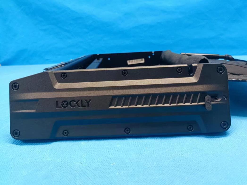
2ASIVPGV528WG30
Apr 21, 2023Lockly Smart Safe
Equipment Class
DTS - Digital Transmission System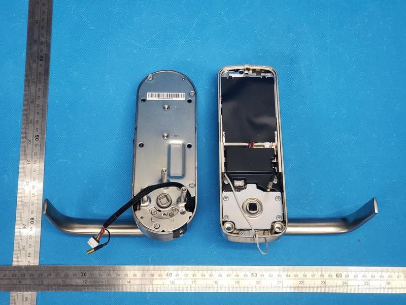
2ASIVPGD698
Apr 02, 2023Lockly Guard Vision
Equipment Class
DTS - Digital Transmission System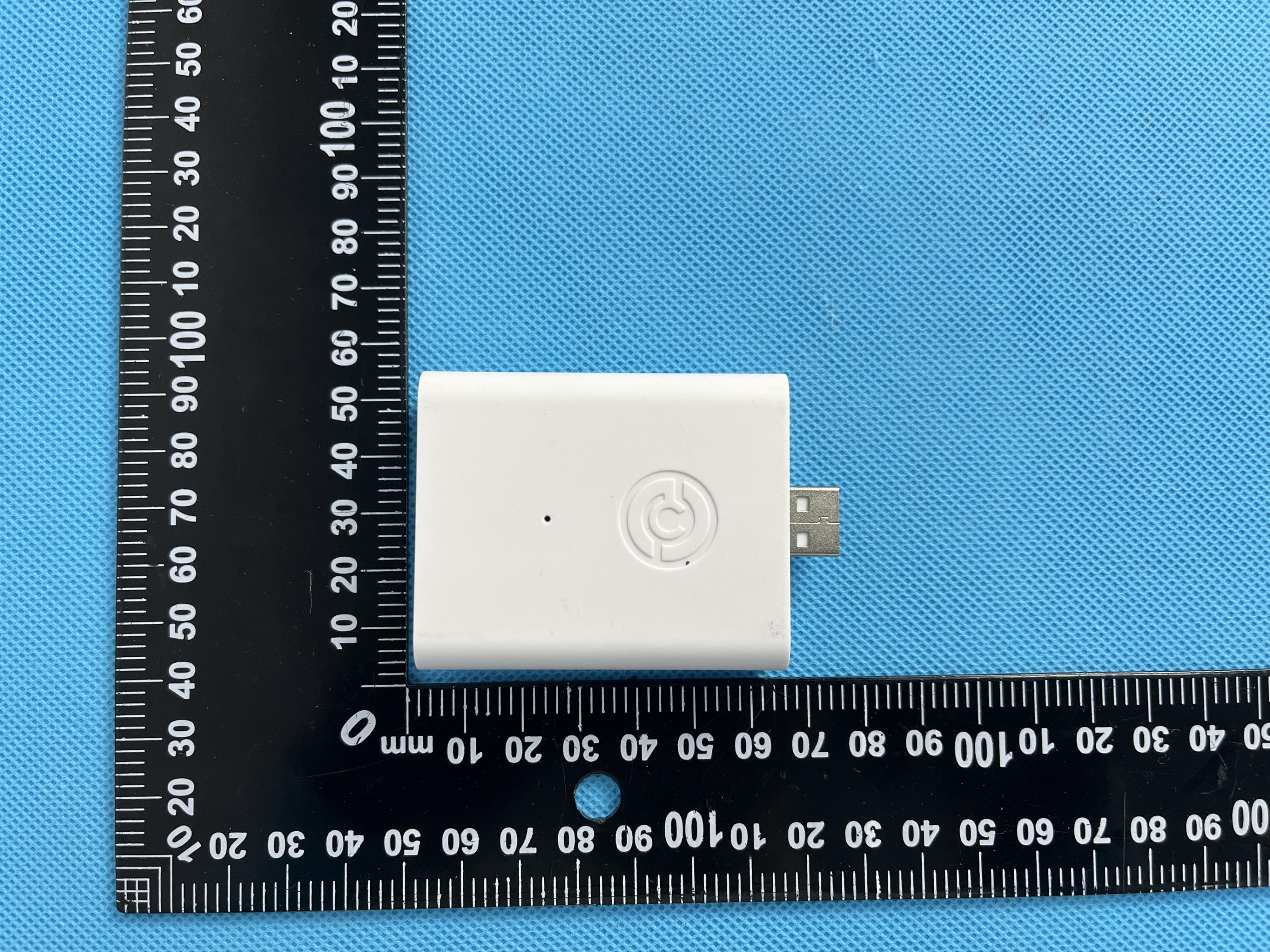
2ASIVPGH200UM
Feb 27, 2023ENABLES WI-FI, RF &BLE CONNECTIVITY FOR LOCKLY SMART LOCKS
Equipment Class
DTS - Digital Transmission System
2ASIV-PGI302FC
Jan 10, 2023LOCKLY GUARD INGRESS
Equipment Class
DXX - Part 15 Low Power Communication Device Transmitter