2ASIVPGH122VISION CONNECT HUB
PIN GENIE, INC. DBA LOCKLY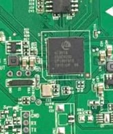
Click to zoom
Application Details
- Equipment Class
- DSS - Part 15 Spread Spectrum Transmitter
- Date of Grant
- Apr 02, 2020
- Application Purpose
- Original Equipment
- Date of Application
- Apr 02, 2020
- Equipment Note
- VISION CONNECT HUB
- Frequency Range
- 2403.01000000 - 2471.01000000
- Company
- PIN GENIE, INC. DBA LOCKLY
- Country
- United States
Documents & Files
Document Text
Text extracted from the exhibit documents filed with the FCC. Open a document above to read the original.
Users Manual
ERP机型:PL35G2UQ-GL-SMT00010A-V1 Designed:何承龙Date:2020-03-27 描述: 说明书:PL35G2UQ/PGD1128FPW,SMT000,REV.A,196×196MM, 封,底面:128g双粉纸双面过哑油,双面印4C+2专,内页80g书纸,双面印单黑,18页36面装订本, RoHS2.0,REACH,Prop65,POPs,PAHs ERP P/N: REV:0.3 KCMC 封面 7540C2915C KYMC SMART LOCK + VIDEO DOORBELL USER MANUAL DEADBOLT EDITION VISION ™ Table of Contents TABLE OF CONTENTS 2.1 Product Overview - Outside 2.2 Product Overview - Inside 2.3 Understanding Your New Lock 2.4 Keypad Display Switch 2.5 Factory Reset 2.6 Program | Pairing Button 2.7 Rebooting Your Lock 2.8 Low Battery Section 1 - Product Highlights Section 2 - Product Overview Section 3 - Using Your Smart Lock 3.1 Configuring Access 3.2 Adding a Fingerprint 3.3 Fingerprint Scanning Directions 3.4 Fingerprint Scanning Tips & Troubleshoot Section 4 - Locking and Unlocking 1.1 Product Features 4.2 Locking / Unlocking using Fingerprints 4.3 Locking / Unlocking using App 4.4 Locking / Unlocking using Physical Key 4.5 Locking and Unlocking with Voice 4.6 Safe Mode Section 5- Advanced Features Section 7 - Important Notes 7.1 Important Notes Section 8 - Cleaning 8.1 Cleaning 1 2 3 4 5 5 6 7 9 8 15 16 17 18 19 20 22 26 27 Section 6 - Re-keying 29 30 Section 9 - Safety Precautions 9.1 Safety Precautions31 4.1 Locking / Unlocking using Access Codes 6.1 Re-keying 28 For additional support, visit http://lockly.com/help or email [email protected] 5.1 Video Doorbell 5.2 Offline Access Code (OAC) 5.3 Sub-Admin Access 2.9 Changing The Battery 10 11 13 14 Video Monitoring and Recording See who's at your front door with Live View camera streaming, real-time high-resolution video from your smartphone. Video recordings are stored locally with no monthly fees. Patented Anti-Peep PIN Genie ® Keypad Digits are randomly displayed on the keypad ensuring access codes to be undetectable to intruders after repeated use. Numbers are randomly distributed across 4 buttons, with 3 numbers in each button. Users can press any button showing their number. Location of the numbers are always different everytime someone uses the keypad, making it hard for prying eyes to guess the correct code. Multiple Access Codes & Monitoring Store up to 18 Access Codes for family, friends and guests, as well as monitor entry and exit records. Advanced 3D Fingerprint Recognition Biometric Fingerprint Recognition protocol allows up to 99 registered fingerprints to be used and accepts only actual fingerprints - preventing lifted prints from being used. Live Monitoring and Voice Assistant Control Through your smartphone, monitor door access from anywhere in the world and securely control who comes and goesYou can also control your Lockly smart lock using your voice through Amazon Alexa and the Google Home Assistant. Complete Privacy The exterior displayed keypad can be locked and switched off using the simple ON/OFF toggle from the inside panel. The owner can prevent others trying to input the passcode from the outside and entering the home Offline Access Code TM (OAC) The offline access code can allow owners to issue access codes, set the allowed access duration, all without Lockly ever connecting to the internet, so in case of power outage, you can still magically and remotely issue Access Codes without any connection to the web. Auto-Lock Users no longer have to worry about forgetting to lock the door. With Auto Lock enabled, Lockly will automatically auto-lock the door based on your customized time setting. Tamper Proof Keyhole and 9V Battery Socket The door can be opened with physical backup keys. Receive notification whenever there's an attempt to tamper your lock. There is also a 9V battery connection socket for emergency power backup to access the keypad in case your smart lock runs out of battery. 1.1 Product Features SECTION 1.11 2.1 Product Overview- Exterior SECTION 2.12 9V Battery Emergency Charging Socket Restart Pin Hole OK Button Low Battery Alert Fingerprint Sensor Key Hole Key Hole Cover Video Camera Microphone Screen Lock Icon Video Doorbell Button Video Doorbell Light Indicator Bluetooth Icon Speaker 2.2 Product Overview - Inside SECTION 2.2 3 Display Keypad Switch Thumbturn Low Battery|Door Sensor LED Doorbell Program Button Reset Button Battery Cover 2.3 Understanding Your New Lock SECTION 2.3 After the installation of your new Lockly Vision TM , understanding some key functions of operating your smart lock is important. The next sections will walk you through configuring Access Codes, adding fingerprints, video doorbell recording, resetting, pairing, configuring your Offline Access Code TM (OAC) and other features of your lock. For any questions you can always visit http://lockly.com/help for assistance. Don’t forget that in order for Lockly Vision TM to work with full features, it is required to pair it with the Lockly App available for both iOS and Android smart devices . Please download the app by visiting the link below. 4 Scan or visit Lockly.com/app SECTION 2.45 2.5 Factory Reset Button In order to restore the Lockly to factory default settings, you must have your “Activation Code” available. The Activation Code can be found on the Activation Code Card (PART V) that came with your smart lock. After you have the Activation Code ready, push the reset button on the back panel of the Lockly to perform your reset. Once the smart lock has been reset, all the data previously stored will be deleted. Press Reset Button for one (1) second 2.4 Keypad Display Switch For you peace of mind, the exterior keypad screen can be locked and turned off by using the ON/OFF switch at the back panel (PART G) of the smart lock. When it is switched off, people who are outside cannot enter any access codes to unlock the door. OFF ON Reset Button Open the Lockly smartphone app to add your lock using the Activation Code 6 Program Button RESET 2.6 Program |Pairing Button In case you need to re-pair your lock to your Vision Connect hub, follow the steps below: 1. Slide up the battery cover and press the Program button once until…
Text truncated - open the document above for the full version.
External Photos
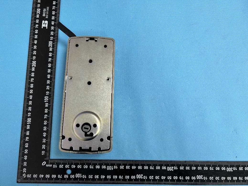
Report No.: W EXHIBI EUT View 1 EUT View 2 WTX20X030 T 2 - EUT 1 2 10995W-1 T EXTER RNAL PH HOTOGR APHS Mo FCC odel: PGH122 C Part 15.247 2 Report No.: W EUT View 3 EUT View 4 WTX20X030 3 4 10995W-1 Mo FCC odel: PGH122 C Part 15.247 2 Report No.: W EUT View 5 EUT View 6 WTX20X030 5 6 10995W-1 Mo FCC odel: PGH122 C Part 15.247 2 Report No.: W EUT View 7 WTX20X030 7 10995W-1 Mo FCC odel: PGH122 C Part 15.247 2
ID Label/Location Info
Report No.: W EXHIBI Proposed Specificatio n silk-screened Proposed WTX20X030 T 1 - PRO FCC ID La ns: Text is b d onto the EU Label Loca 10995W-1 ODUCT L abel Forma black in colo UT or shall be ation on EU LABELIN at r and justifie e affixed at a UT FCC NG ed. Labels ar conspicuous ID Label Lo re printed in location on t cation indelible in k the EUT. Mo FCC k on perman odel: PGH122 C Part 15.247 nent adhesive 2 e
Internal Photos
Report No.: W EXHIBI EUT Housi n EUT Housi n WTX20X030 T 3 - EUT ng and Boar ng and Boar 10995W-1 T INTER rd View 1 rd View 2 NAL PHO OTOGRA APHS Mo FCC odel: PGH122 C Part 15.247 2 Report No.: W Solder Boa r Solder Boar WTX20X030 rd-Compone rd-Compone 10995W-1 ent View 1 ent View 2 Mo FCC odel: PGH122 C Part 15.247 2 Report No.: W Solder Boar Antenna V i WTX20X030 rd-Compone iew 10995W-1 ent View 3 2.4G Ante enna Mo FCC odel: PGH122 C Part 15.247 2
RF Exposure Info
1. MAXIMUM PERMISSIBLE EXPOSURE (MPE) 1.1 General Information Client Information Applicant: PIN GENIE, INC. DBA LOCKLY Address of applicant: 555 California Street, Suite 4925, San Francisco, CA 94104 U.S.A Manufacturer: Smart Technologies & Investment Ltd. Address of manufacturer: Qing Long Road, Long Jian Tian Village, Huang Jiang Town, Dong Guan, Guang Dong, China General Description of EUT: Product Name: VISION CONNECT HUB Brand Name: / Model No.: PGH122 Adding Model(s): / FCC ID: 2ASIVPGH122 Rated Voltage: Power Port:DC5V Power Adapter: Model:617058 Input: AC100~240V-50/60Hz, 0.15A Output: DC5V,1A Technical Characteristics of EUT: Frequency Range: 2403.01-2471.01MHz RF Output Power: 19.07dBm (Conducted) Modulation: GFSK Quantity of Channels: 18 Channel Separation: 4MHz Type of Antenna: External Antenna Antenna Gain: 2.0dBi 1.2 Standard Applicable According to §1.1307(b)(1) and KDB 447498 D01 General RF Exposure Guidance v06, system operating under the provisions of this section shall be operating in a manner that the public is not exposed to radio frequency energy level in excess limit for maximum permissible exposure. (a) Limits for Occupational / Controlled Exposure Frequency range (MHz) Electric Field Strength (E) (V/m) Magnetic Field Strength (H) (A/m) Power Density (S) (mW/cm 2 ) Averaging Times | E | 2 , | H | 2 or S (minutes) 0.3-3.0 614 1.63 (100)* 6 3.0-30 1842/f 4.89/f (900/f)* 6 30-300 61.4 0.163 1.0 6 300-1500 / / F/300 6 1500-100000 / / 5 6 (b) Limits for General Population / Uncontrolled Exposure Frequency range (MHz) Electric Field Strength (E) (V/m) Magnetic Field Strength (H) (A/m) Power Density (S) (mW/cm 2 ) Averaging Times | E | 2 , | H | 2 or S (minutes) 0.3-1.34 614 1.63 (100)* 30 1.34-30 824/f 2.19/f (180/f)* 30 30-300 27.5 0.073 0.2 30 300-1500 / / F/1500 30 1500-100000 / / 1 30 Note: f = frequency in MHz: * = Plane-wave equivalents power density 1.3 MPE Calculation Method S = (30*P*G) / (377*R 2 ) S = power density (in appropriate units, e.g., mw/cm 2 ) P = power input to the antenna (in appropriate units, e.g., mw) G = power gain of the antenna in the direction of interest relative to an isotropic radiator, the power gain factor is normally numeric gain. R = distance to the center of radiation of the antenna (in appropriate units, e.g., cm) 1.4 MPE Calculation Result Maximum Tune-Up output power: 20 (dBm) Maximum peak output power at antenna input terminal: 100(mW) Prediction distance: >20(cm) Prediction frequency: 2403.01 (MHz) Antenna gain: 2.0(dBi) Directional gain (numeric gain): 1.58 The worst case is power density at prediction frequency at 20cm: 0.0315(mw/cm 2 ) MPE limit for general population exposure at prediction frequency: 1 (mw/cm 2 ) Result: Pass
Test Report
Model: PGH122 Report No.: WTX20X03010995W-1 Page 1 of 41 FCC Part 15.247 FCC Part 15C Measurement and Test Report For PIN GENIE, INC. DBA LOCKLY 555 California Street, Suite 4925, San Francisco, CA 94104 U.S.A FCC ID: 2ASIVPGH122 FCC Rule(s): FCC Part 15.247 Product Description: VISION CONNECT HUB Tested Model: PGH122 Report No.: WTX20X03010995W-1 Sample Receipt Date: Mar.18, 2020 Tested Date: Mar.18, 2020 to Mar.23, 2020 Issued Date: Mar.23, 2020 Tested By: Mike Shi / Engineer Reviewed By: Lion Cai / RF Manager Approved & Authorized By: Silin Chen / Manager Prepared By: Shenzhen SEM Test Technology Co., Ltd. 1/F, Building A, Hongwei Industrial Park, Liuxian 2nd Road, Bao'an District, Shenzhen, P.R.C.(518101) Tel.: +86-755-33663308 Fax.: +86-755-33663309 Website: www.semtest.com.cn Note: This test report is limited to the above client company and the product model only. It may not be duplicated without prior permitted by Shenzhen SEM Test Technology Co., Ltd. Model: PGH122 Report No.: WTX20X03010995W-1 Page 2 of 41 FCC Part 15.247 TABLE OF CONTENTS 1. GENERAL INFORMATION ................................................................................................................................... 4 1.1 PRODUCT DESCRIPTION FOR EQUIPMENT UNDER TEST (EUT) ............................................................................... 4 1.2 TEST STANDARDS ................................................................................................................................................... 5 1.3 TEST METHODOLOGY ............................................................................................................................................. 5 1.4 TEST FACILITY ....................................................................................................................................................... 5 1.5 EUT SETUP AND TEST MODE ................................................................................................................................. 6 1.6 MEASUREMENT UNCERTAINTY .............................................................................................................................. 7 1.7 TEST EQUIPMENT LIST AND DETAILS ..................................................................................................................... 8 2. SUMMARY OF TEST RESULTS ......................................................................................................................... 10 3. RF EXPOSURE ....................................................................................................................................................... 11 3.1 STANDARD APPLICABLE ....................................................................................................................................... 11 3.2 TEST RESULT........................................................................................................................................................ 11 4. ANTENNA REQUIREMENT ................................................................................................................................ 12 4.1 STANDARD APPLICABLE ....................................................................................................................................... 12 4.2 EVALUATION INFORMATION ................................................................................................................................ 12 5. FREQUENCY HOPPING SYSTEM REQUIREMENTS ................................................................................... 13 5.1 STANDARD APPLICABLE ....................................................................................................................................... 13 5.2 FREQUENCY HOPPING SYSTEM............................................................................................................................. 13 5.3 EUT PSEUDORANDOM FREQUENCY HOPPING SEQUENCE .................................................................................... 13 6. QUANTITY OF HOPPING CHANNELS AND CHANNEL SEPARATION ................................................... 14 6.1 STANDARD APPLICABLE ....................................................................................................................................... 14 6.2 TEST PROCEDURE ................................................................................................................................................. 14 6.3 SUMMARY OF TEST RESULTS/PLOTS .................................................................................................................... 14 7. DWELL TIME OF HOPPING CHANNEL .......................................................................................................... 17 7.1 STANDARD APPLICABLE ....................................................................................................................................... 17 7.2 TEST PROCEDURE ................................................................................................................................................. 17 7.3 SUMMARY OF TEST RESULTS/PLOTS .................................................................................................................... 18 8. 20DB BANDWIDTH ............................................................................................................................................... 22 8.1 STANDARD APPLICABLE ....................................................................................................................................... 22 8.2 TEST PROCEDURE ................................................................................................................................................. 22 8.3 SUMMARY OF TEST RESULTS/PLOTS .................................................................................................................... 23 9. RF OUTPUT POWER .....................................................…
Text truncated - open the document above for the full version.
Test Setup Photos
Report No.: W EXHIBI Conducted Radiation E WTX20X030 T 4 - TES Emission Te Emission Tes 10995W-1 ST SETUP est Setup st Setup (Belo P PHOTO ow 30MHz) OGRAPH HS Mo FCC odel: PGH122 C Part 15.247 2 Report No.: W Radiation E Radiation E WTX20X030 Emission Tes Emission Tes 10995W-1 st Setup (30M st Setup (1GH MHz to 1GHz Hz to 18GHz z) z) Mo FCC odel: PGH122 C Part 15.247 2 Report No.: W Radiation E WTX20X030 Emission Tes 10995W-1 st Setup (Abo ove 18GHz) Mo FCC odel: PGH122 C Part 15.247 2
Contact Information
Applicant
Cindy zhou(COO)
Test Firm
Waltek Testing Group (Shenzhen) Co., Ltd.Jandy So
Technical Specifications
| # | Rule Parts | Frequency Range | Power Output |
|---|---|---|---|
| 1 | 15C | 2.40 GHz - 2.47 GHz | 80.70 mW |
Other Applications from PIN GENIE, INC. DBA LOCKLY
2ASIVPGD768FNU
Jun 22, 2024Lockly Guard Fingerprint Deadbolt 728FZ Z-Wave Smart Lock, Lockly Guard Deadbolt 728Z Z-Wave Smart Lock
Equipment Class
DTS - Digital Transmission System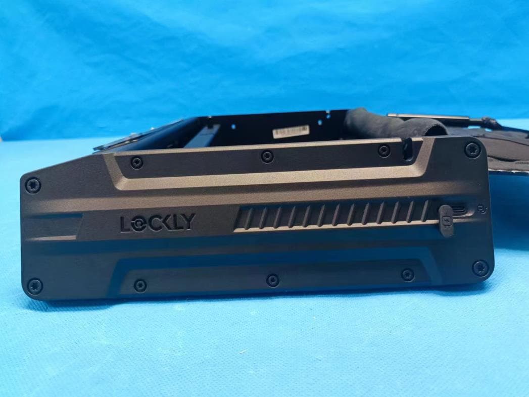
2ASIVPGV528WG30
Apr 21, 2023Lockly Smart Safe
Equipment Class
DTS - Digital Transmission System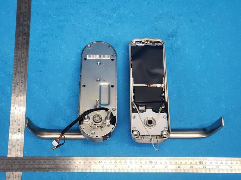
2ASIVPGD698
Apr 02, 2023Lockly Guard Vision
Equipment Class
DTS - Digital Transmission System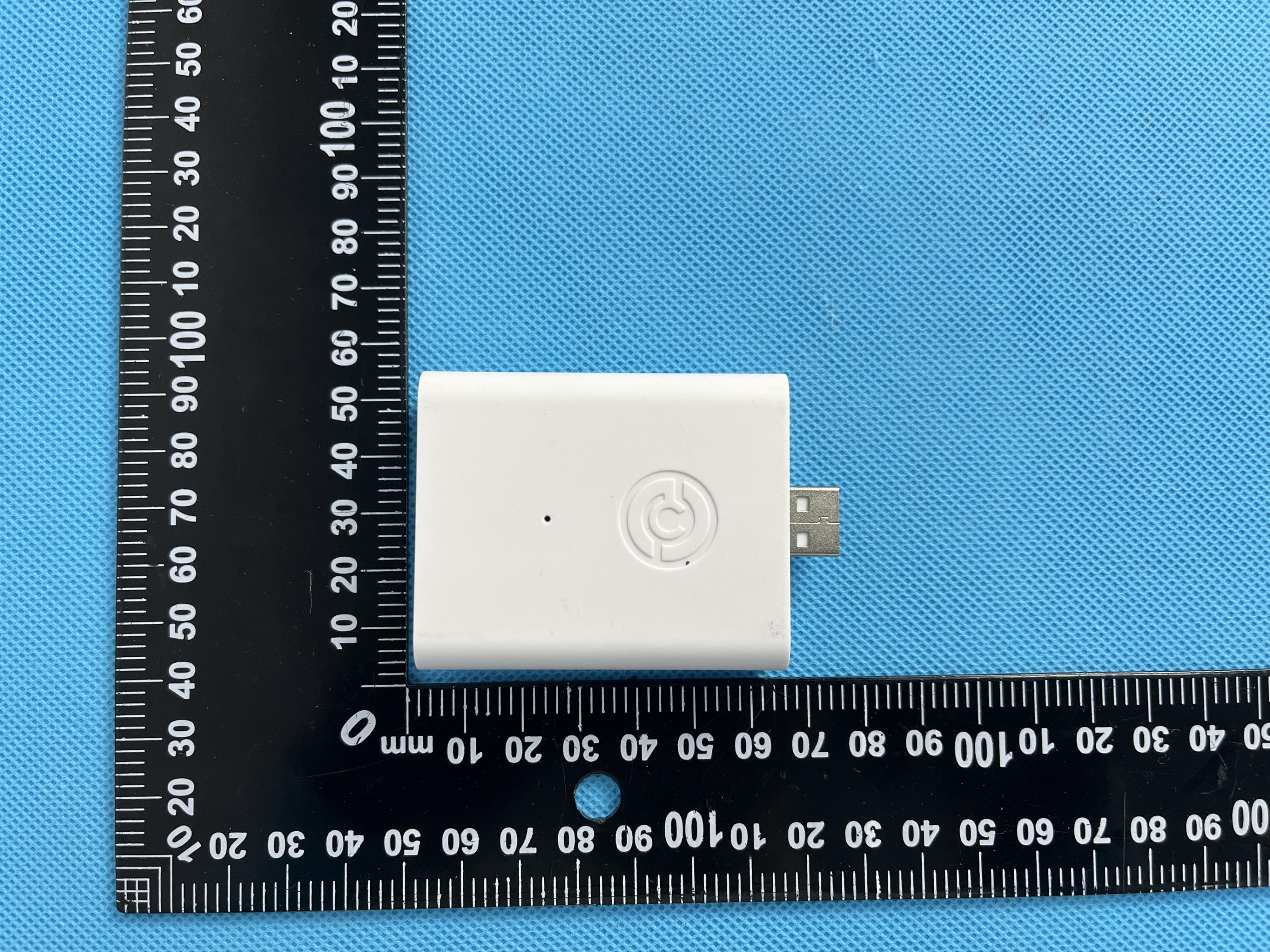
2ASIVPGH200UM
Feb 27, 2023ENABLES WI-FI, RF &BLE CONNECTIVITY FOR LOCKLY SMART LOCKS
Equipment Class
DTS - Digital Transmission System
2ASIV-PGI302FC
Jan 10, 2023LOCKLY GUARD INGRESS
Equipment Class
DXX - Part 15 Low Power Communication Device Transmitter