2ATPH-JNET1-915MHZRF module
JUGANU Ltd.
Click to zoom
Application Details
- Equipment Class
- DTS - Digital Transmission System
- Date of Grant
- Jun 22, 2020
- Application Purpose
- Original Equipment
- Date of Application
- Jun 19, 2020
- Equipment Note
- RF module
- Frequency Range
- 903.00000000 - 927.00000000
- Company
- JUGANU Ltd.
- Country
- Israel
Documents & Files
Document Text
Text extracted from the exhibit documents filed with the FCC. Open a document above to read the original.
Users Manual
1 JNET1 User Manual General description Juganu’s Medium bandwidth Network-on-lights, the JNET1©, provides an easy to deploy, highly reliable, secure, flexible, dynamic and intelligent connectivity infrastructure. The GPS Card fills two roles: to provide location of the node, and provide an accurate time. The JNET1 Card acts as JNET1© network components that together with other JNET-1 Luminaries Wireless Controlles create an autonomous self-management scalable Luminaries network. The network is designed to control and manage up to hundreds of thousands of lights in the modern city complicated environment. The JNET1© network use a proprietary network protocol, using 902-928 MHz sub- Giga unlicensed spectrum. The Figure below depicts the basic JNET1© network architecture. Network Creation Each JNET1 Node is a network member. By using the JNET1 Card resources (software, CPU and its transceivers) a JNET1© network is automatically created. The network demonstrates two significant capabilities: Self-Healing for finding the fastest and most reliable paths to send data. Self-Improvement for detecting poor inter Node radio links (noisy or busy channels) and selects alternative nodes/ Channels to keep communication integrity. 2 Maintenance and Deployment Easy deployment - The self-configuring network automatically accepts a new node into the existing structure without any need in adjustments by a network administrator. The network is easy to install and uninstall – it doesn't need any pre-installation design or installation planning in order to be stable and operate. Specification Highlights Frequency Range 903-927 MHz 500 kbps Effective Data Throughput 200 kbps Transmitter Output Up to 14 dBm Receiver Sensitivity -95 dBm for 1% PER (data rate of 200 kbps) Spreading Technique Frequency agility 2GFSK Inter Node Communication- Juganu proprietary Addressing Paradigm JNET is a source-routing tree solution employs a proprietary MAC address paradigm Wireless Network Security Counter Mode Cipher Block Chaining Message Authentication Code Protocol over AES128, Pre-Shared Key. Operating Temperature -40°C to +55°C Humidity 95% non-condensing Power Connection 12V DC through Connector on board J6. 3 OEM Integrators Notices This device is intended only for OEM integrators under the following conditions: 1) The antenna must be installed such that 20 cm is maintained between the antenna and users, and 2) The transmitter module may not be co-located with any other transmitter or antenna. As long as 2 conditions above are met, further transmitter test will not be required. However, the OEM integrator is still responsible for testing their end-product for any additional compliance requirements required with this module installed. IMPORTANT NOTE: In the event that these conditions cannot be met (for example certain laptop configurations or co-location with another transmitter), then the FCC authorization is no longer considered valid and the FCC ID cannot be used on the final product. In these circumstances, the OEM integrator will be responsible for re- evaluating the end product (including the transmitter) and obtaining a separate FCC or authorization. The OEM integrator has to be aware not to provide information to the end user regarding how to install or remove this RF module in the user’s manual of the end product which integrate this module. The user’s manual for OEM integrators must include the following information in a prominent location: “IMPORTANT NOTE: To comply with FCC RF exposure compliance requirements, the antenna used for this transmitter must be installed to provide a separation distance of at least 20 cm from all persons and must not be co-located or operating in conjunction with any other antenna or transmitter." 4 FCC statements This device complies with Part 15 of the FCC Rules. Operation is subject to two conditions: (1) This device may not cause harmful interference, and (2) this device must accept any interference that may be received or that may cause undesired operation. NOTE: This equipment has been tested and found to comply with the limits for a Class B digital device, pursuant to part 15 of the FCC Rules. These limits are designed to provide reasonable protection against harmful interference in a residential installation. This equipment generates, uses and can radiate radio frequency energy and, if not installed and used in accordance with the instructions, may cause harmful interference to radio communications. However, there is no guarantee that interference will not occur in a particular installation. If this equipment does cause harmful interference to radio or television reception, which can be determined by turning the equipment off and on, the user is encouraged to try to correct the interference by one or more of the following measures: -Reorient or relocate the receiving antenna. -Increase the separation between the equipment and receiver. -Connect the equipment into an outlet on a circuit different from that to which the receiver is connected. -Consult the dealer or an experienced radio/TV technician for help. WARNING! To comply with FCC RF exposure compliance requirements, the device should be located at a distance of at least 20 cm from all persons during normal operation. The antennas used for this product must not be co-located or operated in conjunction with any other antenna or transmitter. Changes or modifications to this equipment not expressly approved by the party responsible for compliance (Juganu Ltd.) could void the user’s authority to operate the equipment.
Cover Letter(s)
To:Telefication B.V. Attn: Dept. FCC TCB Edisonstraat 12A 6902 PK ZEVENAAR The Netherlands June 15, 2020 Subject: Application for certification of a single modular transmitter, FCC ID:2ATPH-JNET1-915MHZ Dear Gentlemen, Please find attached our application for certification of the single modular transmitter, model JNET1 FCC ID:2ATPH-JNET1-915MHZ, prepared in accordance with FCC Rules, parts 2 and 15, subpart C, section15.247. The product testing and this application for certification were performed by Hermon Laboratories, which is recognized and accredited by FCC, Test Firm Registration Number is 927748, Designation Number is IL1001. Hermon Labs responsible person is Mr. Michael Nikishin, EMC and Radio group manager, tel: 011 972 4626 8440, fax:011 972 4628 8277, e-mail:[email protected]. Please send an invoice to Hermon Labs. We hope this application satisfies your requirements. Sincerely yours David Davidov, HW Manager JUGANU Ltd.
Cover Letter(s)
RF_160, Issue 04 Declaration of Authorization We Name: JUGANU Ltd. Address: 1 Yahadut Canada, st . City: Or Yehuda, 6037501. Country: Israel . Declare that: Name Representative of agent: ............. (1) Agent Company name: Hermon Laboratories Ltd.. Address: Harakevet Industrial Zone .. City: Binyamina 30500.. Country Israel . is authorized to apply for Certification of the following product(s): Product description: RF module. Type designation (model name): JNET1. Trademark: ...JUGANU Ltd. Validity/ expiry date March 29, 2021 on our behalf. Date: March 29, 2020 .. City: Or Yehuda .. Name: David Davidov .. (2) Function: HW Manager............................ Signature: .. Notes: (1): Required for FCC application (2): For FCC it must be the Grantee Code “owner” or the authorized agent.
Cover Letter(s)
RF_734_02 04 April 16 Modular Approval Request FCC (KDB 996369 D01 & Part 15.212) FCC ID: 2ATPH-JNET1-915MHZ Items to be covered by Single modular transmitters. Answer from applicant 1. The modular transmitter must have its own RF shielding. Y- the modular transmitter contains shielded RF section 2. The modular transmitter must have buffered modulation/data inputs (if such inputs are provided) to ensure that the module will comply with Part 15 requirements under conditions of excessive data rates or over-modulation. Y- Data rate 500Kbps 3. The modular transmitter must have its own power supply regulation. Y-LDO from 5v to 3.3v 4. The modular transmitter must comply with the antenna requirements of Section 15.203 and 15.204(b)(c). The antenna must either be permanently attached or employ a “unique” antenna coupler (at all connections between the module and the antenna, including the cable). Y- Added two shrinks on the antennas to secure connection 5. The modular transmitter must be tested in a stand-alone configuration, i.e., the module must not be inside another device during testing. This is intended to demonstrate that the module is capable of complying with Part 15 emission limits regardless of the device into which it is eventually installed. Y- the module was tested in stand-alone configuration 6. The modular transmitter must be equipped with either a permanently affixed label or must be capable of electronically displaying its FCC identification number in accordance with 15.212 (a)(1)(vi)(A) / (B). Y- Label exists 7. The modular transmitter must comply with any specific rule or operating requirements applicable to the transmitter and the manufacturer must provide adequate instructions along with the module to explain any such requirements. A copy of these instructions must be included in the application for equipment authorization. For example, there are very strict operational and timing requirements that must be met before a transmitter is authorized for operation under Section 15.231. For instance, data transmission is prohibited, except for operation under Section 15.231(e), in which case there are separate field strength level and timing requirements. Compliance with these requirements must be assured. Y- There is no specific rule or operating requirements applicable to the transmitter with respect to user operation 8. The modular transmitter must comply with any applicable RF exposure requirements. For example, FCC Rules in Sections 1.1310, 2.1091, 2.1093, and specific Sections of Part 15, including 15.319(i), 15.407(f), 15.253(f) and 15.255(g), require that Unlicensed PCS, UNII and millimeter wave devices perform routine environmental evaluation for RF Exposure to demonstrate compliance. In addition, spread spectrum transmitters operating under Section 15.247 are required to address RF Exposure compliance. Modular transmitters approved under other Sections of Part 15, when necessary, may also need to address certain RF Exposure concerns, typically by providing specific installation and operating instructions for users, installers and other interested parties to ensure compliance. Y - The modular transmitter complies with any applicable RF exposure requirements as specified in FCC part 15 section 15.247 and section 1.1310 Name and surname of applicant (or authorized representative): David Davidov Date: 17.03.2020_ Signature:
Cover Letter(s)
FCC, Request for non-disclosure Date: 19-Oct-10 RF_501, Issue 7 Page 1 of 1 Company Name: Juganu Ltd. Address : 1 Yahadut Canada st. City: Or Yehuda 6037501 Country: Israel To: Telefication B.V., Dept. FCC TCB Edisonstraat 12A 6902 PK ZEVENAAR The Netherlands Subject: Request for confidentiality FCC ID: 2ATPH-JNET1-915MHZ Reference number: ###### Dear FCC TCB, 1. Long-Term Confidentiality Pursuant to 47 CFR Section 0.459(a) & (b), we hereby requests non-disclosure and confidential treatment of the following materials submitted in support of FCC certification application: Bill(s) of Material Block Diagrams Operational Description Schematic Diagrams Tune-up Procedure Above materials contain secrets, proprietary and technical information, which would customarily be guarded from competitors under 47 CFR, section 0.457(d)(2). Disclosure or publication or any portion of this company confidential material to other parties could cause substantial competitive harm and provide unjustified benefits for competitors. 2. Short-Term Confidentiality (STC) Pursuant to Public Notice DA 04-1705 of the Commission’s policy, in order to comply with the marketing regulations in 47 CFR §2.803 and the importation rules in 47 CFR §2.1204, a pplicant hereby requests Short-Term Confidential treatment of the following materials (note 1): Internal Photos User’s Manual Test Set-up Photos External Photos Justification: Company IP, we don’t to expouse our design to our competitors. Planned Release Date STC: 180 days after grant date (notes 2, 3, 4, 5). If no date is given, 45 days from grant date will be used. Date: March 29, 2020 Name and signature of applicant: David Davidov Notes: 1) A document or type of document can only have ONE type of confidentiality! 2) Short-Term confidentiality is in principle for 45 days from date of grant; it can be extended max 3 times (total time 180 days max.)! 3) FCC must be informed when marketing begins earlier. 4) Release takes place automatically thus extension must be requested in time. Telefication does not remind you of this! 5) Request for extension or for release must be received by Telefication at least 7 days before date of actual marketing or before expiration of the STC period
External Photos
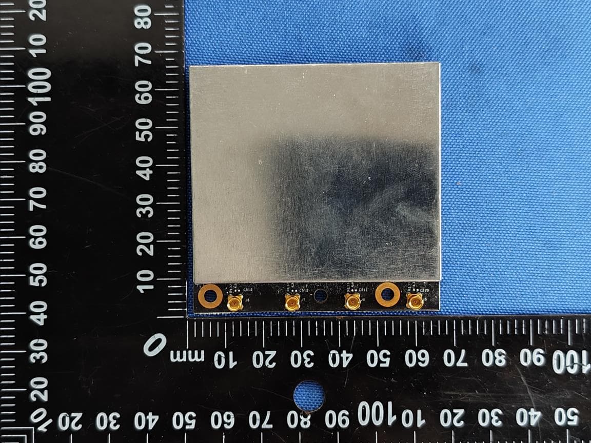
Juganu Ltd. FCC ID:2ATPH-JNET1-915MHZ Page 1 of 4 EXTERNAL PHOTOGRAPHS This document contains 3 photographs Juganu Ltd. FCC ID:2ATPH-JNET1-915MHZ Page 2 of 4 Photograph No.1 JNET1 general view Juganu Ltd. FCC ID:2ATPH-JNET1-915MHZ Page 3 of 4 Photograph No.2 JNET1 antennas with shrink shrink shrink Juganu Ltd. FCC ID:2ATPH-JNET1-915MHZ Page 4 of 4 Photograph No.3 JNET1 bottom view
ID Label/Location Info
Juganu Ltd. FCC ID:2ATPH-JNET1-915MHZ Page 1 of 1 Label Label location Label with FCC ID:2ATPH-JNET1-915MHZ is placed here. The statement according to §15.19(a)(3) is located in User manual, page 4 (Application exhibit User_manual_32978).
Internal Photos
Juganu Ltd. FCC ID:2ATPH-JNET1-915MHZ Page 1 of 7 INTERNAL PHOTOGRAPHS This document contains 6 photographs Juganu Ltd. FCC ID:2ATPH-JNET1-915MHZ Page 2 of 7 Photograph No.1 JNET1 view with antennas with shrink shrink shrink Juganu Ltd. FCC ID:2ATPH-JNET1-915MHZ Page 3 of 7 Photograph No.2 JNET1 top view Juganu Ltd. FCC ID:2ATPH-JNET1-915MHZ Page 4 of 7 Photograph No.3 JNET1 PCB second side view Juganu Ltd. FCC ID:2ATPH-JNET1-915MHZ Page 5 of 7 Photograph No.4 PCB card top view without shields Juganu Ltd. FCC ID:2ATPH-JNET1-915MHZ Page 6 of 7 Photograph No.5 GPS card top view Juganu Ltd. FCC ID:2ATPH-JNET1-915MHZ Page 7 of 7 Photograph No.6 GPS card bottom view
Operational Description
Juganu Ltd. FCC ID:2ATPH‐JNET1‐915MHZ 1 JNET1 Operational Description General description Juganu’s Medium bandwidth Network-on-lights, the JNET1©, provides an easy to deploy, highly reliable, secure, flexible, dynamic and intelligent connectivity infrastructure. The GPS Card fills two roles: to provide location of the node, and provide an accurate time. The JNET1 Card acts as JNET1© network components that together with other JNET-1 Luminaries Wireless Controlles create an autonomous self-management scalable Luminaries network. The network is designed to control and manage up to hundreds of thousands of lights in the modern city complicated environment. The JNET1© network use a proprietary network protocol, using 902-928 MHz sub-Giga unlicensed spectrum. The Figure below depicts the basic JNET1© network architecture. Network Creation Each JNET1 Node is a network member. By using the JNET1 Card resources (software, CPU and its transceivers) a JNET1© network is automatically created. The network demonstrates two significant capabilities: Self-Healing for finding the fastest and most reliable paths to send data. Self-Improvement for detecting poor inter Node radio links (noisy or busy channels) and selects alternative nodes/ Channels to keep communication integrity. Juganu Ltd. FCC ID:2ATPH‐JNET1‐915MHZ 2 Specification Highlights Frequency Range 903-927 MHz 500 kbps Effective Data Throughput 200 kbps Transmitter Output Up to 14 dBm Receiver Sensitivity -95 dBm for 1% PER (data rate of 200 kbps) Spreading Technique Frequency agility 2GFSK Inter Node Communication- Juganu proprietary Addressing Paradigm JNET is a source-routing tree solution employs a proprietary MAC address paradigm Wireless Network Security Counter Mode Cipher Block Chaining Message Authentication Code Protocol over AES128, Pre-Shared Key. Operating Temperature -40°C to +55°C Humidity 95% non-condensing Power Connection 12V DC through Connector on board J6.
RF Exposure Info
Juganu Ltd. FCC ID:2ATPH-JNET1-915MHZ Exposure limit according to §15.247(i) The RF moduleis classified as a mobile device. The FCC limit for power density for general population/uncontrolled exposure is f/1500 mW/cm 2 for 300 – 1500 MHz frequency range: P = 903/1500 = 0.6 mW/cm 2 The power density P (mW/cm 2 ) = P T / 4 r 2 P T i s the transmitted power, which is equal to the peak transmitter output power 10.45 dBm plus maximum antenna gain 2.5 dBi, the maximum equivalent isotropically radiated power EIRP is P T =10.45 dBm + 2.5 dBi = 12.95 dBm = 19.72 mW. The power density at 20 cm (minimum safe distance, required for mobile devices), calculated as follows: 19.72 mW / 4 (20 cm) 2 = 0.004 mW/cm 2 << 0.6 mW/cm 2 General public cannot be exposed to dangerous RF level.
Test Report
Hermon Laboratories Ltd. P.O. Box 23, Binyamina 3055001, Israel Tel. +972 4628 8001 Fax. +972 4628 8277 E-mail: [email protected] Page 1 of 68 Report ID: JUGRAD_FCC.32978.docx Date of Issue: 17-Jun-20 ELECTRICAL TESTING 0839.01 TEST REPORT ACCORDING TO: FCC 47CFR part 15 2019 subpart C §15.247 FCC 47CFR part 15 2019 subpart B §15.107, §15.109 FOR: Juganu Ltd. RF module Model: JNET1 FCC ID: 2ATPH-JNET1-915MHZ This report is in conformity with ISO/ IEC 17025. The "A2LA Accredited" symbol endorsement applies only to the tests and calibrations that are listed in the scope of Hermon Laboratories accreditation. The test results relate only to the items tested. This test report shall not be reproduced in any form except in full with the written approval of Hermon Laboratories Ltd. Report ID: JUGRAD_FCC.32978.docx Date of Issue: 17-Jun-20 Page 2 of 68 Table of contents 1 Applicant information ..................................................................................................................................................... 3 2 Equipment under test attributes .................................................................................................................................... 3 3 Manufacturer information .............................................................................................................................................. 3 4 Test details .................................................................................................................................................................... 3 5 Tests summary .............................................................................................................................................................. 4 6 EUT description ............................................................................................................................................................. 5 6.1 General information ....................................................................................................................................................... 5 6.2 Ports and lines .............................................................................................................................................................. 5 6.3 Test configuration .......................................................................................................................................................... 5 6.4 Transmitter characteristics ............................................................................................................................................ 6 7 Transmitter tests according to 47CFR part 15 subpart C requirements ........................................................................ 7 7.1 Minimum 6 dB bandwidth .............................................................................................................................................. 7 7.2 Peak output power ...................................................................................................................................................... 11 7.3 Field strength of spurious emissions ........................................................................................................................... 18 7.4 Band edge radiated emissions .................................................................................................................................... 38 7.5 Peak spectral power density ....................................................................................................................................... 43 7.6 Conducted emissions .................................................................................................................................................. 48 7.7 Antenna requirements ................................................................................................................................................. 51 8 Emission tests according to 47CFR part 15 subpart B requirements .......................................................................... 52 8.1 Conducted emissions .................................................................................................................................................. 52 8.2 Radiated emission measurements .............................................................................................................................. 55 9 APPENDIX A Test equipment and ancillaries used for tests ....................................................................................... 59 10 APPENDIX B Test equipment correction factors ......................................................................................................... 60 11 APPENDIX C Measurement uncertainties .................................................................................................................. 66 12 APPENDIX D Test facility description ......................................................................................................................... 67 13 APPENDIX E Specification references ........................................................................................................................ 67 14 APPENDIX F Abbreviations and acronyms ................................................................................................................. 68 Report ID: JUGRAD_FCC.32978.docx Date of Issue: 17-Jun-20 Page 3 of 68 1 Applicant information Client name: Juganu Ltd. Address: 1 Yahadut Canada St., Or Yehuda 6037501, Israel Telephone: +972-52-279-0969 E-mail: [email protected] Contact name: Mr.David Davidov 2 Equipment under test attributes Product name: RF module Product type: Data transmit network unit Model(s): JNET1 Part number: JL-AS000398 Serial number: A0:00:4E:2A Hardware version: 50 Receipt date 28-Mar-19 3 Manufacturer information Manufacturer name: Juganu Ltd. Address: 1 Yahadut Canada St., Or Yehuda …
Text truncated - open the document above for the full version.
Test Setup Photos
Juganu Ltd. FCC ID:2ATPH-JNET1-915MHZ Page 1 of 9 SETUP PHOTOGRAPHS This document contains 8 photographs Juganu Ltd. FCC ID:2ATPH-JNET1-915MHZ Page 2 of 9 Photograph No.1 Setup for OBW measurements Juganu Ltd. FCC ID:2ATPH-JNET1-915MHZ Page 3 of 9 Photograph No.2 Setup for spurious emission measurements in the anechoic chamber below 30 MHz Juganu Ltd. FCC ID:2ATPH-JNET1-915MHZ Page 4 of 9 Photograph No.3 Setup for carrier field strength and spurious emission measurements in the anechoic chamber below 1000 MHz Juganu Ltd. FCC ID:2ATPH-JNET1-915MHZ Page 5 of 9 Photograph No.4 Setup for peak output power in the anechoic chamber, EUT close view in X-axis position Juganu Ltd. FCC ID:2ATPH-JNET1-915MHZ Page 6 of 9 Photograph No.5 Setup for peak output power in the anechoic chamber, EUT close view in Y-axis position Juganu Ltd. FCC ID:2ATPH-JNET1-915MHZ Page 7 of 9 Photograph No.6 Setup for peak output power in the anechoic chamber, EUT close view in Z-axis position Juganu Ltd. FCC ID:2ATPH-JNET1-915MHZ Page 8 of 9 Photograph No.7 Setup for spurious emission measurements in the anechoic chamber above 1000 MHz Juganu Ltd. FCC ID:2ATPH-JNET1-915MHZ Page 9 of 9 Photograph No.8 Setup for conducted emission measurements on the AC power lines
Contact Information
Applicant
David Davidov(HW Manager)
Technical Contact
Hermon Laboratories Ltd.Michael Nikishin
[email protected]972 4626 8440
Harakevet Industrial zone, P.O.Box 23 · Israel
Non-Technical Contact
JUGANU Ltd.David Davidov
[email protected]972-52-279-0969
Test Firm
Hermon Laboratories Ltd.George Shleimovich
Technical Specifications
| # | Rule Parts | Frequency Range | Power Output |
|---|---|---|---|
| 1 | 15C | 903 MHz - 927 MHz | 13.00 mW |
Other Applications from JUGANU Ltd.
2ATPH-JS-WI-6
Mar 09, 2026RF PCBAs
Equipment Class
NII - Unlicensed National Information Infrastructure TX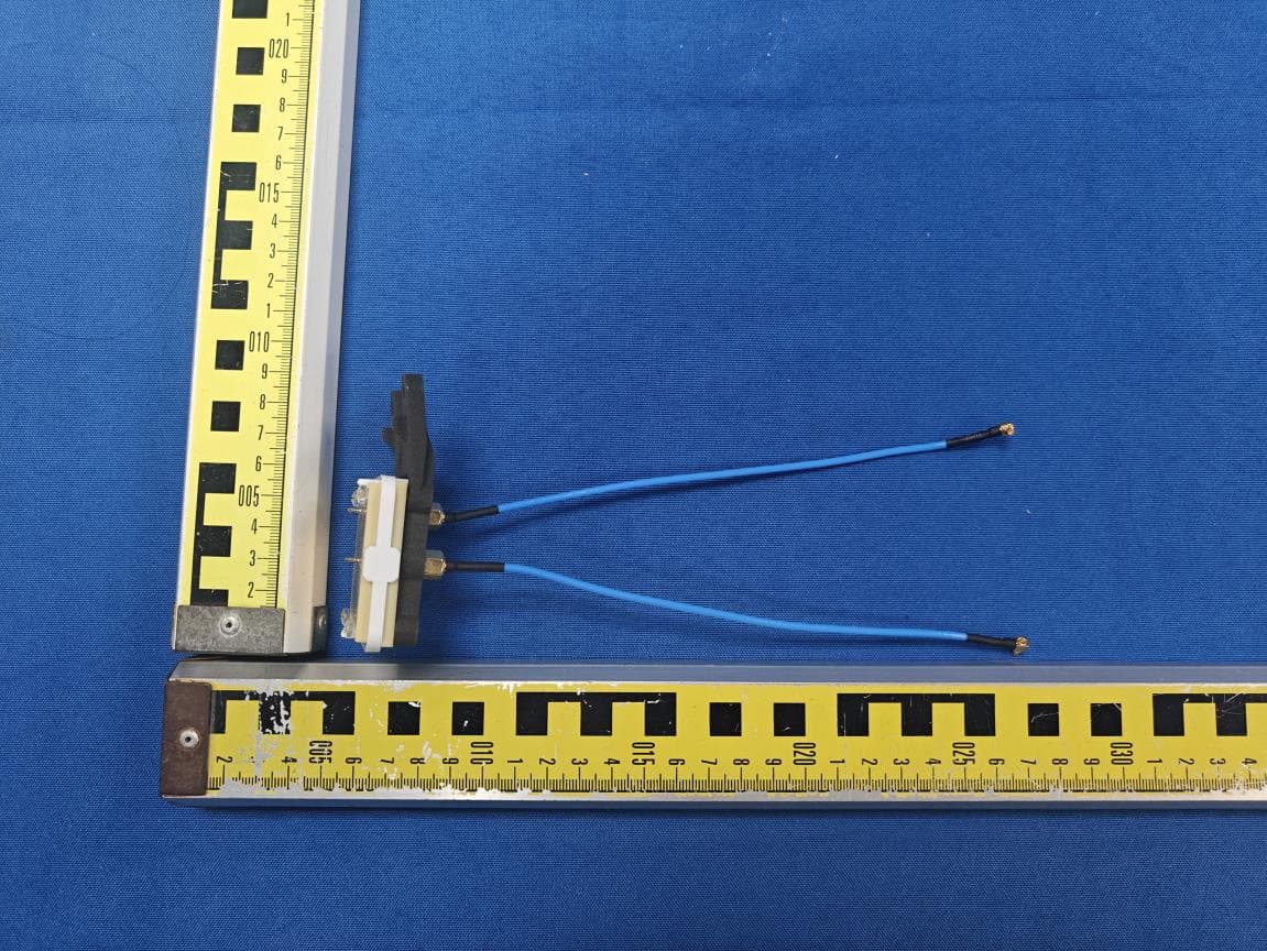
2ATPH-JS-WI-2-4
Mar 06, 2026RF PCBAs
Equipment Class
DTS - Digital Transmission System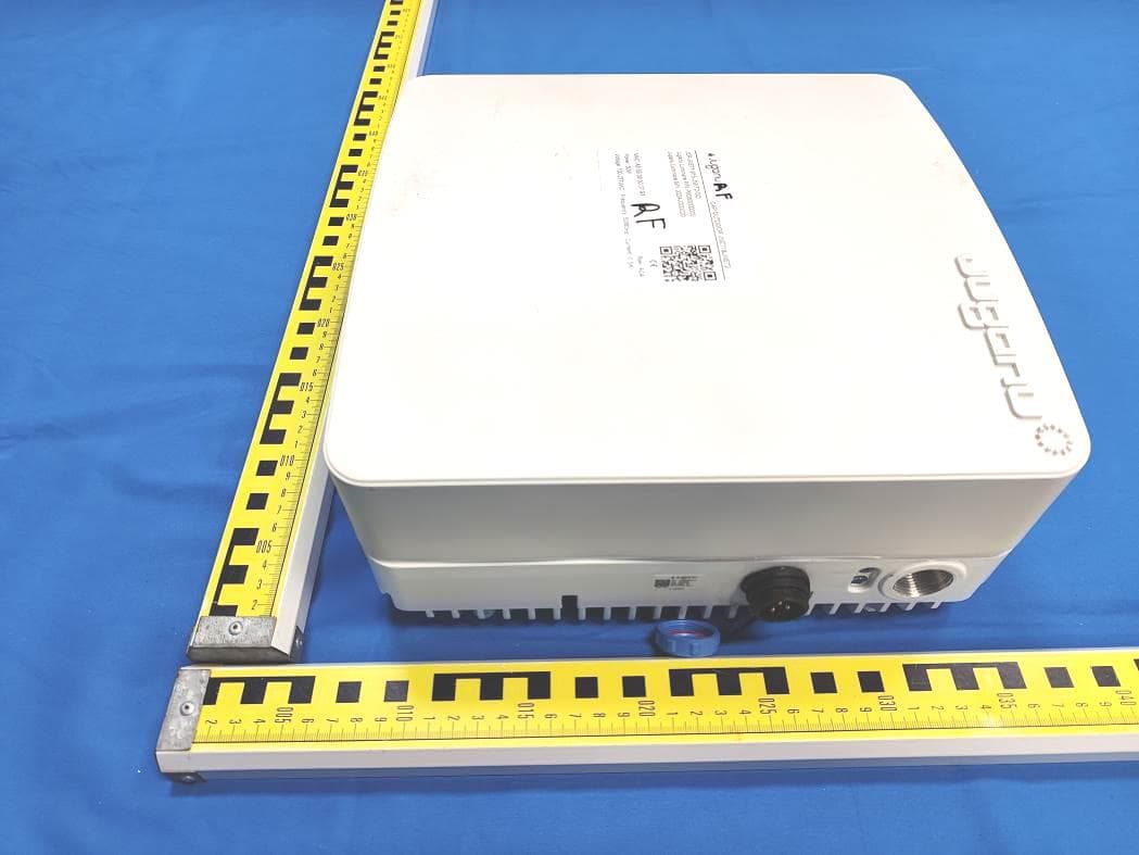
2ATPH-JNET2-OD
Jan 29, 2023CAP OUTDOOR
Equipment Class
NII - Unlicensed National Information Infrastructure TX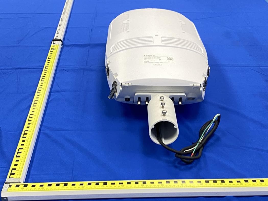
2ATPH-PHOENIX1
Jul 03, 2022Wireless us part
Equipment Class
NII - Unlicensed National Information Infrastructure TX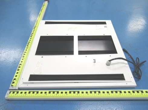
2ATPH-JPP
May 17, 2021JPROTECT
Equipment Class
CYY - Communications Receiver used w/Pt 15 Transmitter